BEJLSM4200LCD MONITOR
LG Electronics USA, Inc.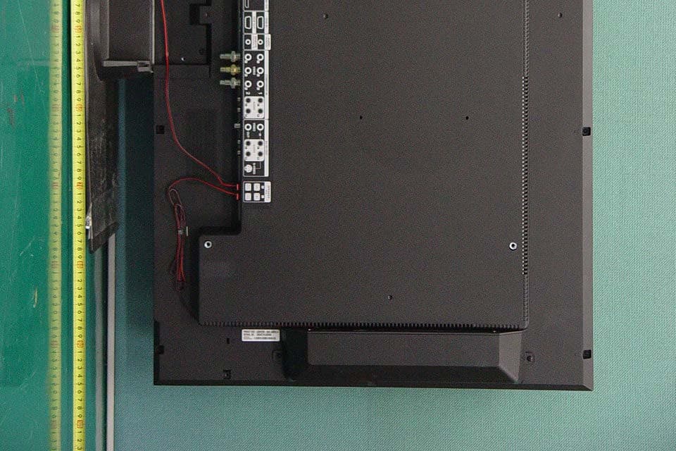
Click to zoom
Application Details
- Equipment Class
- JBP - Part 15 Class B Computing Device Peripheral
- Date of Grant
- Mar 03, 2011
- Application Purpose
- Original Equipment
- Date of Application
- Mar 03, 2011
- Equipment Note
- LCD MONITOR
- Company
- LG Electronics USA, Inc.
- Country
- United States
Documents & Files
Document Text
Text extracted from the exhibit documents filed with the FCC. Open a document above to read the original.
Users Manual
Order Number : GETEC-C1-11-034 FCC Part 15 subpart B Test Report Number : GETEC-E3-11-013 Page 1 / 1 EUT Type: LCD Monitor FCC ID.: BEJLSM4200 APPENDIX G : USER’S MANUAL OWNER’S MANUAL MONITOR SIGNAGE MONITOR SIGNAGE MODELS LSM4200 www.lge.com Please read this manual carefully before operating your set and retain it for future reference. 1 First, check if the following parts are all present. Stand (1) Screws (6) Parts 1. Take the parts for the stand out of the box and assemble them as shown in the picture. 2. Place a soft cloth on the table and put the product with the screen facing downward.Connect the stand as shown in the following picture. cable management (1) 3. Use the screws to secure the stand on the rear side of the product as shown in the diagram. - Only on some models. - Can be purchased separately if necessary. Connecting the stand 2 Connecting the Speakers Mount the product onto the speaker by using a screw as shown in the following connect the speaker cable. - Only on some models. - Can be purchased separately if necessary. When the speaker is installed. *Connect the input terminal with a proper color match. Type 1 3 Connecting the Speakers Mount the product onto the speaker by using a screw as shown in the following connect the speaker cable. - Only on some models. Type 2 When the speaker is installed. *Connect the input terminal with a proper color match. * This feature is not available in all model. Remove the paper. Cable holder After installing your speakers, use holders and cable ties to organize the speaker cables. Cable tie * This feature is not available in all model. 4 "When installing Portrait, rotate it clockwise based on its front." To install Portrait 5 Using the Remote Control Name of the Remote Control Buttons 123 456 78 0 9 * •AV Button •Sleep Button When watching AV, RGB PC,HDMI/DVI ,Component1, Component2 The product will be automatically turned off after a certain period of time. Press this button repetitively to select an appropriate time duration • PSM Button - Toggles through preset video settings. • Menu Button •Check Button •Volume Button Volume up and down • Mute button There is not a function which is supported •UP and Down buttons Bring up and down direction adjustment. •ARC button Aspect Ratio Correction. Toggles through aspect ratio options. • Auto Button Automatic adjustment function (Operational for the analog signal only) •Exit Button There is not a function which is supported There is not a function which is supported There is not a function which is supported •Power On/Off Button •Input Select Button (See next page) 6 Using the Remote Control AV Component1 Component2 RGB PC HDMI/DVI •AV Button Toggles through video 123 456 78 0 9 * If you press the button once, the following Input Signal Window will appear. Select the signal type you want using the button. •Input Select Button 1. Slide off the battery cover. 2. Insert the batteries with correct polarity (+/-). 3. Close the battery cover. • Dispose of used batteries in the recycle bin to prevent environmental pollution. Inserting batteries into remote control. Input AV Component1 Component2 RGB PC HDMI/DVI AAA Type 7 Name and Function of the Parts Rear View Power Connector : Connect the power cord RS-232C Serial Ports RGB PC, HDMI/DVI Ports - HDMI Supports High Definition input and HDCP (High-bandwidth Digital Content Protection). Some devices require HDCP in order to display HD signals. PC Sound Jack : Connect the audio cable to the *LINE OUT jack of the PC sound card. Wired Remote Control Port AV Ports Speaker Ports *LINE OUT A terminal used to connect to the speaker including a built-in amplifier (Amp). Make sure that the connecting terminal of the PC sound card is checked before connecting. If the Audio Out of PC sound card has only Speaker Out, reduce the PC volume. If the Audio Out of the PC sound card supports both Speaker Out and Line Out, convert to Line Out using the card jumper of the program (Refer to the Sound Card Manual). AV IN/OUT * The product image in the user’s guide could be different from the actual image. 8 First of all, see if the computer, product and the peripherals are turned off. Then, connect the signal input cable. When connecting with the D-Sub signal input cable. When connecting with the HDMI to DVI signal input cable (not included). MAC Macintosh Adapter (not included) Use the standard Macintosh adapter since an incompatible adapter is available in the market. (Different signaling system) Rear side of the product. Connecting to External Devices Connect the power cord. B A B A PC When Connecting to your PC PC/MAC PC Rear side of the product. Rear side of the product. PC Rear side of the product. Connect the Audio cable. (not included) * User must use shielded signal interface cables (D-sub 15 pin cable, DVI cable) with ferrite cores to maintain standard compliance for the product. 9 Select an input signal. Press the INPUT button on the remote control to select the input signal. Or, press the SOURCE button on the back of the product. INPUTSET •How to connect to two computers. Connect the signal cables ( HDMI to DVIand D-Sub) to each computer. Press the INPUT button on the remote control to select the computer to use. • Directly connect to a grounded power outlet or power strip (three prong connector.) Note Turn on power by pressing the power button on the product. Turn on the PC. ON/OFF AUTO/SET SOURCE Power button SOURCE AUTO/SET When connecting with a D-Sub signal input cable. • Select RGB PC: 15-pin D-Subanalog signal. When connecting with a HDMI to DVI signal input cable. • Select HDMI/DVI : HDMI to DVIDigital signal. B A Connecting to External Devices 2 1 Input AV Component1 Component2 RGB PC HDMI/DVI Input AV Component1 Component2 RGB PC HDMI/DVI 10 Use this function when displaying ANALOG RGB inputs of a PC to the other product. RGB IN RGB OUT RGB IN RGB OUT RGB IN RGB OUT RGB IN RGB OUT Product 1 • To use different products connected to each other Conne…
Text truncated - open the document above for the full version.
Cover Letter(s)
SCS-F18: Project and Product Certification Representative Authorization Letter Page 1 of 2 Rev 2.0 2206 Ringwood Avenue San Jose, CA 95131 Tel: 408-526-1188 Fax: 408-526-1088 Email: [email protected] Project and Product Certification Representative Authorization Letter Revision History Reason for Amendment (current / obsolete) From To Approved Date Initial Release (current) 1.0 1.0 Nov-14-2006 Revised wording (current) 1.0 2.0 Sept–25-2007 SCS-F18: Project and Product Certification Representative Authorization Letter Page 2 of 2 Rev 2.0 March 4, 2011 To: SIEMIC, INC. 2206 Ringwood Avenue, San Jose, CA 95131 USA Dear Sir/Madam, Re: Project and Product Certification Representative Authorization Letter We, LG Electronics Inc., hereby authorize SIEMIC, INC. to act as a Certification Body for certifying for the following project(s): Product Name: LCD Monitor FCC ID: BEJLSM4200 We affirm that between SIEMIC and LG Electronics Inc., any difference in understanding, including test plan, measurement methods, applicable standards and relevant procedures and processes have been resolved prior to commencement of testing activities. Sincerely, Christopher Johnson, Sr. Manager LG Electronics USA LG Electronics USA 1000 Sylvan Avenue, En glewood Cliffs, NJ 07632, USA
Cover Letter(s)
Confidentiality Request Letter Revision History Reason for Amendment (current / obsolete) From To Approved Date Initial Release (current) 1.0 1.0 Nov-14-2006 SCS-F19: Confidentiality Request Letter Rev 1.0 Nov 14, 2006 Federal Communications Commission Authorization and Evaluation Division March 4, 2011 Confidentiality Request regarding application for certification of FCC ID: BEJLSM4200 We hereby request confidential treatment of information accompanying this application as outlined below: Exhibit Type File Name BLOCK DIAGRAM LSM4200_BlkDia.pdf The above materials contain trade secrets and proprietary information not customarily released to the public. The public disclosure of these materials may be harmful to the applicant and provide unjustified benefits to its competitors. In addition to above mentioned documents, pursuant to Public DA 04-1705 of the Commission’s policy, in order to comply with the marketing regulations in 47 CFR 2.803 and the importation rules in 47 CFR 2.1204, while ensuring that business sensitive information remains confidential until the actual marketing of newly authorized devices. We are requesting the commission to grant short-term confidentiality request on the following Exhibit Type File Name TEST SET UP PHOTOGRAPHS LSM4200 _Tsup.pdf EXTERNAL PHOTOGRAPHS LSM4200 _ExtPho.pdf INTERNAL PHOTOGRAPHS LSM4200 _IntPho.pdf USER’S MANUAL LSM4200 _UseMan.pdf The applicant understands that pursuant to Section 0.457 of the Rules, disclosure of this application and all accompanying documentation will not be made before the date of the Grant for this application. Sincerely, Christopher Johnson, Sr. Manager LG Electronics USA LG Electronics USA 1000 Sylvan Avenue, En glewood Cliffs, NJ 07632, USA
External Photos
Order Number : GETEC-C1-11-034 FCC Part 15 subpart B Test Report Number : GETEC-E3-11-013 Page 1 / 12 EUT Type: LCD Monitor FCC ID.: BEJLSM4200 APPENDIX E : EXTERNAL PHOTOGRAPHS Order Number : GETEC-C1-11-034 FCC Part 15 subpart B Test Report Number : GETEC-E3-11-013 Page 2 / 12 EUT Type: LCD Monitor FCC ID.: BEJLSM4200 Order Number : GETEC-C1-11-034 FCC Part 15 subpart B Test Report Number : GETEC-E3-11-013 Page 3 / 12 EUT Type: LCD Monitor FCC ID.: BEJLSM4200 Order Number : GETEC-C1-11-034 FCC Part 15 subpart B Test Report Number : GETEC-E3-11-013 Page 4 / 12 EUT Type: LCD Monitor FCC ID.: BEJLSM4200 Order Number : GETEC-C1-11-034 FCC Part 15 subpart B Test Report Number : GETEC-E3-11-013 Page 5 / 12 EUT Type: LCD Monitor FCC ID.: BEJLSM4200 Order Number : GETEC-C1-11-034 FCC Part 15 subpart B Test Report Number : GETEC-E3-11-013 Page 6 / 12 EUT Type: LCD Monitor FCC ID.: BEJLSM4200 Order Number : GETEC-C1-11-034 FCC Part 15 subpart B Test Report Number : GETEC-E3-11-013 Page 7 / 12 EUT Type: LCD Monitor FCC ID.: BEJLSM4200 Order Number : GETEC-C1-11-034 FCC Part 15 subpart B Test Report Number : GETEC-E3-11-013 Page 8 / 12 EUT Type: LCD Monitor FCC ID.: BEJLSM4200 Order Number : GETEC-C1-11-034 FCC Part 15 subpart B Test Report Number : GETEC-E3-11-013 Page 9 / 12 EUT Type: LCD Monitor FCC ID.: BEJLSM4200 Order Number : GETEC-C1-11-034 FCC Part 15 subpart B Test Report Number : GETEC-E3-11-013 Page 10 / 12 EUT Type: LCD Monitor FCC ID.: BEJLSM4200 Order Number : GETEC-C1-11-034 FCC Part 15 subpart B Test Report Number : GETEC-E3-11-013 Page 11 / 12 EUT Type: LCD Monitor FCC ID.: BEJLSM4200 Order Number : GETEC-C1-11-034 FCC Part 15 subpart B Test Report Number : GETEC-E3-11-013 Page 12 / 12 EUT Type: LCD Monitor FCC ID.: BEJLSM4200
ID Label/Location Info
Order Number : GETEC-C1-11-034 FCC Part 15 subpart B Test Report Number : GETEC-E3-11-013 Page 1 / 2 EUT Type: LCD Monitor FCC ID.: BEJLSM4200 APPENDIX B : ID SAMPLE LABEL & LOCATION Order Number : GETEC-C1-11-034 FCC Part 15 subpart B Test Report Number : GETEC-E3-11-013 Page 2 / 2 EUT Type: LCD Monitor FCC ID.: BEJLSM4200 LABELLING REQUIREMENTS The label shown shall be permanently affixed at a conspicuous location on the device and be readily visible to the user at the time of purchase. ID Label ID Label Location of EUT ID Label
Internal Photos
Order Number : GETEC-C1-11-034 FCC Part 15 subpart B Test Report Number : GETEC-E3-11-013 Page 1 / 23 EUT Type: LCD Monitor FCC ID.: BEJLSM4200 APPENDIX F : INTERNAL PHOTOGRAPHS Order Number : GETEC-C1-11-034 FCC Part 15 subpart B Test Report Number : GETEC-E3-11-013 Page 2 / 23 EUT Type: LCD Monitor FCC ID.: BEJLSM4200 Order Number : GETEC-C1-11-034 FCC Part 15 subpart B Test Report Number : GETEC-E3-11-013 Page 3 / 23 EUT Type: LCD Monitor FCC ID.: BEJLSM4200 Order Number : GETEC-C1-11-034 FCC Part 15 subpart B Test Report Number : GETEC-E3-11-013 Page 4 / 23 EUT Type: LCD Monitor FCC ID.: BEJLSM4200 Order Number : GETEC-C1-11-034 FCC Part 15 subpart B Test Report Number : GETEC-E3-11-013 Page 5 / 23 EUT Type: LCD Monitor FCC ID.: BEJLSM4200 Order Number : GETEC-C1-11-034 FCC Part 15 subpart B Test Report Number : GETEC-E3-11-013 Page 6 / 23 EUT Type: LCD Monitor FCC ID.: BEJLSM4200 Order Number : GETEC-C1-11-034 FCC Part 15 subpart B Test Report Number : GETEC-E3-11-013 Page 7 / 23 EUT Type: LCD Monitor FCC ID.: BEJLSM4200 Order Number : GETEC-C1-11-034 FCC Part 15 subpart B Test Report Number : GETEC-E3-11-013 Page 8 / 23 EUT Type: LCD Monitor FCC ID.: BEJLSM4200 Order Number : GETEC-C1-11-034 FCC Part 15 subpart B Test Report Number : GETEC-E3-11-013 Page 9 / 23 EUT Type: LCD Monitor FCC ID.: BEJLSM4200 Order Number : GETEC-C1-11-034 FCC Part 15 subpart B Test Report Number : GETEC-E3-11-013 Page 10 / 23 EUT Type: LCD Monitor FCC ID.: BEJLSM4200 Order Number : GETEC-C1-11-034 FCC Part 15 subpart B Test Report Number : GETEC-E3-11-013 Page 11 / 23 EUT Type: LCD Monitor FCC ID.: BEJLSM4200 Order Number : GETEC-C1-11-034 FCC Part 15 subpart B Test Report Number : GETEC-E3-11-013 Page 12 / 23 EUT Type: LCD Monitor FCC ID.: BEJLSM4200 Order Number : GETEC-C1-11-034 FCC Part 15 subpart B Test Report Number : GETEC-E3-11-013 Page 13 / 23 EUT Type: LCD Monitor FCC ID.: BEJLSM4200 Order Number : GETEC-C1-11-034 FCC Part 15 subpart B Test Report Number : GETEC-E3-11-013 Page 14 / 23 EUT Type: LCD Monitor FCC ID.: BEJLSM4200 Order Number : GETEC-C1-11-034 FCC Part 15 subpart B Test Report Number : GETEC-E3-11-013 Page 15 / 23 EUT Type: LCD Monitor FCC ID.: BEJLSM4200 Order Number : GETEC-C1-11-034 FCC Part 15 subpart B Test Report Number : GETEC-E3-11-013 Page 16 / 23 EUT Type: LCD Monitor FCC ID.: BEJLSM4200 Order Number : GETEC-C1-11-034 FCC Part 15 subpart B Test Report Number : GETEC-E3-11-013 Page 17 / 23 EUT Type: LCD Monitor FCC ID.: BEJLSM4200 Order Number : GETEC-C1-11-034 FCC Part 15 subpart B Test Report Number : GETEC-E3-11-013 Page 18 / 23 EUT Type: LCD Monitor FCC ID.: BEJLSM4200 Order Number : GETEC-C1-11-034 FCC Part 15 subpart B Test Report Number : GETEC-E3-11-013 Page 19 / 23 EUT Type: LCD Monitor FCC ID.: BEJLSM4200 Order Number : GETEC-C1-11-034 FCC Part 15 subpart B Test Report Number : GETEC-E3-11-013 Page 20 / 23 EUT Type: LCD Monitor FCC ID.: BEJLSM4200 Order Number : GETEC-C1-11-034 FCC Part 15 subpart B Test Report Number : GETEC-E3-11-013 Page 21 / 23 EUT Type: LCD Monitor FCC ID.: BEJLSM4200 Order Number : GETEC-C1-11-034 FCC Part 15 subpart B Test Report Number : GETEC-E3-11-013 Page 22 / 23 EUT Type: LCD Monitor FCC ID.: BEJLSM4200 Order Number : GETEC-C1-11-034 FCC Part 15 subpart B Test Report Number : GETEC-E3-11-013 Page 23 / 23 EUT Type: LCD Monitor FCC ID.: BEJLSM4200
Test Report
Order Number : GETEC-C1-11-034 FCC Class B Certification Test Report Number : GETEC-E3-11-013 Page2 / 28 EUT Type: LCD Monitor FCC ID.: BEJLSM4200 CONTENTS 1. GENERAL INFORMATION ...................................................................................................................................... 3 2. INTRODUCTION ........................................................................................................................................................ 4 3. PRODUCT INFORMATION ...................................................................................................................................... 5 3.1 DESCRIPTION OF EUT .............................................................................................................................................. 5 3.2 SUPPORT EQUIPMENT / CABLES USED ..................................................................................................................... 6 3.3 MODIFICATION ITEM(S) ........................................................................................................................................... 7 4. DESCRIPTION OF TESTS ......................................................................................................................................... 8 4.1 TEST CONDITION ...................................................................................................................................................... 8 4.2 CONDUCTED EMISSION ............................................................................................................................................ 9 4.3 RADIATED EMISSION .............................................................................................................................................. 10 5. CONDUCTED EMISSION ........................................................................................................................................ 11 5.1 OPERATING ENVIRONMENT ................................................................................................................................... 11 5.2 TEST SET-UP ........................................................................................................................................................... 11 5.3 MEASUREMENT UNCERTAINTY.............................................................................................................................. 11 5.4 LIMIT ...................................................................................................................................................................... 12 5.5 TEST EQUIPMENT USED .......................................................................................................................................... 12 5.6 TEST DATA FOR CONDUCTED EMISSION ................................................................................................................ 12 6. RADIATED EMISSION ............................................................................................................................................ 21 6.1 OPERATING ENVIRONMENT ................................................................................................................................... 21 6.2 TEST SET-UP ........................................................................................................................................................... 21 6.3 MEASUREMENT UNCERTAINTY.............................................................................................................................. 21 6.4 LIMIT ...................................................................................................................................................................... 22 6.5 TEST EQUIPMENT USED .......................................................................................................................................... 22 6.6 TEST DATA FOR RADIATED EMISSION .................................................................................................................... 23 7. SAMPLE CALCULATIONS ..................................................................................................................................... 27 7.1 EXAMPLE 1 : ........................................................................................................................................................... 27 7.2 EXAMPLE 2 : ........................................................................................................................................................... 27 8. RECOMMENDATION & CONCLUSION .............................................................................................................. 28 APPENDIX A – ATTESTATION STATEMENT APPENDIX B – ID SAMPLE LABEL & LOCATION APPENDIX C – BLOCK DIAGRAM APPENDIX D – TEST SET-UP PHOTOGRAPHS APPENDIX E – EXTERNAL PHOTOGRAPHS APPENDIX F – INTERNAL PHOTOGRAPHS APPENDIX G – USER’S MANUAL Order Number : GETEC-C1-11-034 FCC Class B Certification Test Report Number : GETEC-E3-11-013 Page3 / 28 EUT Type: LCD Monitor FCC ID.: BEJLSM4200 Scope: Measurement and determination of electromagnetic emissions (EME) of radio frequency devices including intentional and / or unintentional radiators for compliance with technical rules and regulations of the Federal Communications Commission. 1. General Information FCC ID. BEJLSM4200 EUT Type LCD Monitor Model Name LSM4200 Tra de Na me LG Serial Number Prototype Rule Part(s) FCC Part 15 Subpart B Type of Authority Certification Test Procedure(s) ANSI C63.4 (2003) / Canadian standard ICES-003 Dates of Test February 12 ~ March 2, 2011 Place of Test Gumi College EMC Center ( FCC Registration Number: 100749, 443957) 407, Bugok-dong, Gumi-si, Gyeongbuk, Korea. Test Report Number GETEC-E3-11-013 Dates of Issue March 4, 2011 Applicant: LG Electronics Inc. Applicant Address: 19-1, Cheongho-ri, Jinwi-myeon, Pye…
Text truncated - open the document above for the full version.
Test Setup Photos
Order Number : GETEC-C1-11-034 FCC Part 15 subpart B Test Report Number : GETEC-E3-11-013 Page 1 / 3 EUT Type: LCD Monitor FCC ID.: BEJLSM4200 APPENDIX D : TEST SET UP PHOTOGRAPHS Order Number : GETEC-C1-11-034 FCC Part 15 subpart B Test Report Number : GETEC-E3-11-013 Page 2 / 3 EUT Type: LCD Monitor FCC ID.: BEJLSM4200 The Conducted Test Picture and Radiated Test Picture show the worst-case configuration and cable placement. Conducted Test Picture (Front) Conducted Test Picture (Rear) Order Number : GETEC-C1-11-034 FCC Part 15 subpart B Test Report Number : GETEC-E3-11-013 Page 3 / 3 EUT Type: LCD Monitor FCC ID.: BEJLSM4200 Radiated Test Picture (Front) Radiated Test Picture (Rear)
Contact Information
Applicant
David Kim(Team leader, LGEUS NA Policy & Regulatory Affairs)
Test Firm
Gumi University EMC CenterTae-Sig Park
Technical Specifications
| # | Rule Parts | Frequency Range | Power Output |
|---|---|---|---|
| 1 | 15B | - | - |
Other Applications from LG Electronics USA, Inc.

BEJTFHOBINI1F1
Jan 08, 2025Telematics
Equipment Class
DTS - Digital Transmission SystemBEJNT-16Z90TS
Oct 02, 2024Notebook Computer
Equipment Class
DSS - Part 15 Spread Spectrum TransmitterBEJSP-PEW8
Sep 26, 2024Stylus Pen
Equipment Class
DCD - Part 15 Low Power Transmitter Below 1705 kHzBEJ-RSMV2
Sep 24, 2024RF Module
Equipment Class
FDS - Part 15 Field Disturbance SensorBEJTFBMEIBN3EU
Sep 24, 2024Telematics
Equipment Class
NII - Unlicensed National Information Infrastructure TX