BEJLSP500CDMA Fixed Wireless Telephone
LG Electronics USA, Inc.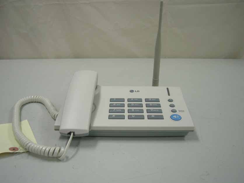
Click to zoom
Application Details
- Equipment Class
- TNB - Licensed Non-Broadcast Station Transmitter
- Date of Grant
- Jun 14, 2006
- Application Purpose
- Original Equipment
- Date of Application
- Jun 14, 2006
- Equipment Note
- CDMA Fixed Wireless Telephone
- Frequency Range
- 824.70000000 - 848.31000000
- Company
- LG Electronics USA, Inc.
- Country
- United States
Documents & Files
Document Text
Text extracted from the exhibit documents filed with the FCC. Open a document above to read the original.
Users Manual
1 Introduction Congratulations on your purchase of the LG Fixed Wireless Terminal that has been designed to operate on the latest digital mobile communications technology, Code Division Multiple Access (CDMA). This CDMA digital technology has greatly enhanced voice clarity and can provide various advanced features. The terminal enables the normal operation and direct connection of standard telephone equipment into the cellular network. The standard unit provides: ▶ Handset ▶ Data Port for repair(RJ-45 Port) ▶ AC Power supply with barrel plug connector ▶ Support Dial tone ▶ Touch tone(DTMF) or Pulse Dialing ▶ Voice-Mail Notification ring alerts you to new voice-mail messages ▶ A signal light(LED) to indicate the status of the unit ▶ Dipole Antenna Some features can not be supported by service provider’s equipment status. For instance, the following features may not be supported: ▶ Speed Dial ▶ Emergency Call ▶ Hot Line Call ▶ Alarm ▶ Outgoing Call Lock ▶ Quick Dial Option with “*” Other features as determined by your service provider. 1.1 Component List 1.2 Front, Rear View of the Terminal 1.3 LED Indicator 1.4 Installation You should follow each step carefully as shown below in order to guarantee proper operation of CDMA Fixed Wireless Telephone. STEP I. Check Components ▶ Fixed Wireless Terminal is supplied with the following standard unit and accessories: 1. LSP-500R Unit-1EA- 2. Dipole Antenna-1EA- 3. User Guide -1EA- 4. AC/DC Power Adapter -1EA- ▶ Please make sure that these components are present and check for evidence of shipping before you begin the unit installation. ▶ If components are missing or damage is found, contact your authorized LGE Service Center immediately. STEP II. Place the Terminal ▶ Place the terminal on the stable flat secure surface area (desk, table, etc.). Avoid direct exposure to the sunlight and damp areas. ▶ Read the SAFETY INFORMATION located at the first part of this document before you place the terminal. STEP III. Connect Components ▶ Connect the Dipole antenna to the TNC connector located at the topside of the terminal. If you have placed the terminal on the flat surface, position the antenna up side. ▶ Connect the battery cable to the DC battery connector at the side of the terminal. - Remove the battery compartment cover. - Connect battery to the connector. - Replace the battery cover. ▶ Connect the AC power supply cable to the DC input port located at the side of the terminal. STEP IV. Check LED Indicators ▶ When you followed the installation instruction STEP I to STEP III, please check the LEDs for normal operation. ▶ When DC power is fed at the first time, LEDs will operate as follows: - During the first seconds, LED is ORANGE, if AC/DC power is applied. - If receiving signal strength is strong enough, then LED is GREEN. - If not, it is ORANGE or OFF. 1.5 Installation Steps Please follow the below procedure to install the unit properly. 2 Basic Operations 2.1 Power On 1. If the LED Indicator is RED, battery is low. 2. When the terminal succeeded in getting the service, LED indicates the strength of the signal(Table 1). Lifting handset on telephone, dial tone is heard and you can enter a phone number. Note: - Not entering any key for 15 seconds warning tone will be produced. - While having maintenance request order or lock order from the system, neither dial tone nor busy tone is produced. Instead of them, there will be no sound and LED will be blinking with RED color simultaneously. 3. If the radio service is not available or radio signal is too weak to detect: The LED is OFF. (No Service status) 2.2 Placing a Call When lifting handset (“off hook”), the terminal determines whether cellular service is available. If it is available, dial tone is produced and a number can be dialed normally. If phone service is not available, LED of the terminal will be OFF and no dial tone will be heard. If user presses “DIAL” button after dialed the number, the terminal makes a call immediately. 2.3 Receiving a Call The telephone rings when an incoming call is detected. Pick up the handset and begin talking. 2.4 Ending a Call When you have completed the call, place the handset back on telephone. Also you can hook flash more than about 1 second to end a call and place a new call without hanging up the handset. 2.5 Warning Tone after Remote Disconnect A warning tone may be heard in the telephone after a remote party hangs up from a call, allowing another call to be initiated after hook-flash. 2.6 Emergency Call When emergency call number is connected once, it will not be terminated unless the called party disconnects the call (Emergency Call Hold Service). Therefore even caller hangs up the telephone, the line will be still connected, so if the caller picks up the telephone again, he can continue talking. If emergency call is connected, cellular service is not supported. As long as your telephone is registered on a system, you can place a call to emergency number even if your telephone is locked or restricted. Please check the available emergency call number with your service provider. 2.7 Power Off When you don’t need to use terminal anymore, you should do power off before removing AC/DC adapter cable. If you do terminal power off, Press Redial/Flash key for 2 seconds. If so, the terminal will LED off and stop all operations. Then you shall separate External Power jack from Terminal. 3 System Features 3.1 Redial/Flash When the Redial/Flash button is presssed it will automatically allow: 1. For immediate dialing after a phone number has been dialed without connection. 2. The use of special cellular services which may be available in your cellular service area. 3.2 ROH (Receiver Off Hook) If the telephone equipment remains “off-hook”, meaning that the handset is left off of its cradle as it would be when you hang up, with no dialing activity for about 60 seconds, a ROH tone emits from the receiver for a period of 60 seconds. This feature may be different or not by cou…
Text truncated - open the document above for the full version.
Cover Letter(s)
June 13, 2006 Federal Communication Commission Equipment Authorization Branch 7435 Oakland Mills Road Columbia, MID 21046 In re : LG Electronics Inc.. FCC ID: BEJLSP500 Single Band WLL Phone Part22 Request for Confidentiality Gentlemen: In accordance with 0.459 of CFR 47, LG Electronics, Inc. hereby requests confidentiality of the Block Diagram, Schematic Diagrams, Operational Description, Technical Specification, Parts List, and Tune-Up Procedure for the above-referenced certification application. These documents contain detailed system and equipment description and related information about the product which LG Electronics Inc. Considers to be proprietary, confidential, and a custom design and, otherwise, would not release to the general public. Since this design is a basis from which future technological products will evolve, LG Electronics Inc. considers this information to be of benefit to its competitors, such that the disclosure of the information in these documents would give competitors an unfair advantage in the market. Sincerely, E.S.Park Chief Research Engineer CDMA Handset Lab LG Electronics Inc. Tel : 82- 2-2033-3850 Fax : 82- 2-2033-2228 [email protected] 459- 9, Kasan-dong,Kemchun-ku Seoul 153- 023, Korea LG Electronics Inc. LGE
Cover Letter(s)
June 13, 2006 Federal Communications Commission Authorization and Evaluation Div. Equipment Authorization Branch 7435 Oakland Mills Road Columbia, MD 21046 In re: LG Electronics Inc. FCC ID: BEJLSP500 Request for Short-Term Confidentiality To Whom It May Concern: In accordance with 0.457 and 0.459 of CFR 47, LG Electronics Inc. requests short-term confidentiality for the test setup photos, external photos, internal photos, and user’s manual of the attached test report. These documents contain detailed system and equipment descriptions and related information about the product, which LG Electronics Inc. considers to be proprietary, confidential, and a custom design and otherwise, would not release to the general public. Since this design is a basis from which future technological products will evolve, LG Electronics feels that this information would be of benefit to its competitors, and that the disclosure of the information in these documents would give our competitors an unfair advantage in the market. Sincerely, E.S.Park Chief Research Engineer CDMA Handset Lab LG Electronics Inc. LG Electronics Inc. LGE Tel : 82-2-2033-3850 Fax : 82-2-2033-2228 [email protected] 459-9, Kasan-dong, Kemchun-ku Seoul 153-023, Korea
Cover Letter(s)
American Telecommunications Certification Body Inc. 6731 Whittier Ave, McLean, VA 22101 June 14, 2006 RE: FCC ID: BEJLSP500_ATCB003576 Attention: Jay Kim I have a few comments on this Application. Please note that further comments may arise in response to answers provided to the questions below. 1. Please note that the center frequency on page 11 of the report is said to be 849MHz. Please note that there is part of the signal form the EUT that is apparently over the limit as it is outside the marker and above 849MHz. Please re-measure and provide data showing clear compliance of the band edge at 849MHz. Dennis Ward mailto:[email protected] The items indicated above must be submitted before processing can continue on the above referenced application. Failure to provide the requested information may result in application termination. Correspondence should be considered part of the permanent submission and may be viewed from the Internet after a Grant of Equipment Authorization is issued. Please do not respond to this correspondence using the email reply button. In order for your response to be processed expeditiously, you must submit your documents through the AmericanTCB.com website. Also, please note that partial responses increase processing time and should not be submitted. Any questions about the content of this correspondence should be directed to the sender.
ID Label/Location Info
Model No : LSP-500, LSP-500R, LSP-500T FCC ID : BEJLSP500 SN : Made In Korea
Test Report
Product Name Model Name Applicant FCC ID LSP-500,LSP-500R,LSP-500T LG Electronics Inc. BEJLSP500 ESTECH CO., LTD Rm. 1015 World Venture Center, 426-5 Gasan-dong, Geumcheon-gu, Seoul, 153-803, Korea. Tel:82-2-867-3201, Fax:82-2-867-3204 ͑͑ESTECH CO., LTD. http://www.estech.co.kr FCC TEST REPORT CDMA Fixed Wireless Telephone Report Number : ESTR0606-0021 of 18 FCC ID : BEJLSP500 Company Name Address Product Name Model No.Manufacturer Serial No. Country of origin Issued DateTested Date ͑͑ESTECH CO., LTD. http://www.estech.co.kr Rm. 1015 World Venture Center, 426-5 Gasan-dong, Geumcheon-gu, Seoul, 153-803, Korea. Tel:82-2-867-3201, Fax:82-2-867-3204 ESTECH CO., LTD FCC Test Report Applicant Product Report Number LSP-500,LSP- 500R,LSP-500T KOREA LG Electronics Inc. o This is certified that the above mentioned products have been tested for the sample provided by client. o No part of this document may not be duplicated or reproduced by any means without the express written permission of Estech Co., Ltd. Standard FCC PART 22 Subpart H Tested by Approved by S.R. Kim/ Engineer (Signature) Jay Kim/ Engineering Manager (Signature) ESTR0606-002 459-9, Kasan-dong, Keumchun-ku, Seoul 153-023, Korea CDMA Fixed Wireless Telephone NONE LG Electronics Inc. Test Result Pass 2006-06-03 2006-04-28 ~ 2006-06-03 Other Report Number : ESTR0606-0022 of 18 FCC ID : BEJLSP500 1. General Information Page 4 2. Laboratory Information Page 5 3. Summary of Test Results Page 5 4. RF Output Power Page 6 5. Occupied Bandwidth Page 8 6. Spurious and Harmonic Emission at Antenna Terminal Page 10 7. Field Strength of Spurious Radiation Page 15 8. Frequency stability Page 17 Contents ͑͑ESTECH CO., LTD. http://www.estech.co.kr Report Number : ESTR0606-0023 of 18 FCC ID : BEJLSP500 1. General Information 1.1 EUT Description Channel Tx :824.70 ~ 848.31MHz CDMA (1013/363/777) CDMA Frequency Rx :869.70 ~ 893.31MHz Adapter: 5VDC(3.5 ~ 6.0VDC) Power Rating ͑͑ ESTECH CO., LTD. http://www.estech.co.kr FCC ID BEJLSP500 Modulation Type Product Name Model Name CDMA Fixed Wireless Telephone LSP-500,LSP-500R,LSP-500T Report Number : ESTR0606-0024 of 18 FCC ID : BEJLSP500 2. Laboratory Information 3. Summary of Test Results Result PASS PASS PASS PASS ͑͑ ESTECH CO., LTD. http://www.estech.co.kr 58-1, Osan-Ri, GaNam-Myon, YeoJoo-Gun, KyungKi-Do, Korea 97-1, Hoiuk-Ri Majang-Myon, Icheon-city, KyungKi-Do, Korea 2.4 Major Accredited Mark Test Item Accredited by KOLAS(ISO/IEC 17025) Head Office EMC Lab(Ichon) EMC Lab(Yanggi) Standard RF Output Power Occupied Bandwidth PASS 2.1 Laboratory Name 2.2 Location 2.3 Quality System Estech Co., Ltd. Rm. 1015, World Venture Center II, 426-5 Gasan-dong Geumcheon-gu, Seoul, 153-803. Korea. Part 22 Field Strength of Spurious Radiation Frequency stability Spurious and Harmonic Emission at Antenna Terminal Report Number : ESTR0606-0025 of 18 FCC ID : BEJLSP500 4. RF Output Power 4.1 Test Procedure 4.2 Test Equipments The following test equipments are used during tests 4.3. Test Results 1013824.70 363835.89 777848.31 24.52 24.50 27.41 26.90 310N BBHA 9120 D BBHA 9120 D SONOMA INSTRUMENT SCHWARZBECK SCHWARZBECK Ch No.Freq (MHz) 24.5026.54 Peak Power Meter(dBm)Peak Power ERP(dBm) Pre Amplifier Horn Antenna Horn Antenna Model ESP17 HP HP Manufacturer Rohde & Schwarz ͑͑ ESTECH CO., LTD. http://www.estech.co.kr Signal Generator Power Meter 83620B EPM-442A Equipment Receiver The EUT was placed on a wooden turn table 3 meters from the receive antenna. The receive antenna height and turn table rotation was adjusted for the highest reading on the receive spectrum analyzer. For CDMA signals, a peak detector is used, with RBW = VBW = 3MHz. For AMPS, GSM, and NADC TDMA signals, a peak detector is used, with RBW = VBW = 1MHz, A Horn antenna was substituted in place of the EUT. This Horn antenna was driven by a signal generator and the level of the signal generator was adjusted to obtain the same receive spectrum analyzer reading. This spurious level is recorded. For reading 1GHz, the above procedure is repeated using horn antennas and the difference between the gain of the horn and an isotropic or dipole antenna are taken into consideration. Report Number : ESTR0606-0026 of 18 FCC ID : BEJLSP500 Antenna gain(dBd) Cable Loss (dB) 824.70 100.671.0 3.3028.8426.5438.5V 835.89 101.001.29 3.3029.4227.4138.5V 848.31 99.831.61 3.3028.5926.9038.5V ͑͑ ESTECH CO., LTD. http://www.estech.co.kr FREQ (MHz) Correction Factor (dB) POL (H/V) Limit (dBm) ERP (dBm) SG Reading (dBm) Receiver Reading (dBuV) Report Number : ESTR0606-0027 of 18 FCC ID : BEJLSP500 5. Occupied Bandwidth 5.1 Test Procedure 5.2 Test Equipments The following test equipments are used during tests 5.3 Test Results The transmitter output is connected to the spectrum analyzer. The RBW is set to 1% of the Emission bandwidth. The VBW is set to 3 times the RBW. The sweep time is coupled. 777848.311.400 363835.891.390 ChannelFrequency(MHz) Manufacturer Agilent JFW ͑͑ESTECH CO., LTD. http://www.estech.co.kr Attenuator EquipmentModel E4407B 50FH-010-5 1013824.701.392 Spectrum Analyzer 26dB Bandwidth(MHz) Report Number : ESTR0606-0028 of 18 FCC ID : BEJLSP500 5.4 Test Plot 26dB Channel Bandwidith(1013) 26dB Channel Bandwidith(363) 26dB Channel Bandwidith(777) ͑͑ESTECH CO., LTD. http://www.estech.co.kr Report Number : ESTR0606-0029 of 18 FCC ID : BEJLSP500 6. Spurious and Harmonic Emission at Antenna Terminal 6.1 Test Procedure 6.2 Test Equipments The following test equipments are used during tests 6.3 Test Results CDMA (Spurious Emission: Band Edge) ChannelFrequencyResultLimitMargin 1013824.70-15.95-13.002.95 777848.31-14.79-13.00 1.79 CDMA (Spurious Emission: Out of Band) ChannelFrequencyResultLimitMargin 1013824.70-25.31-13.0012.31 363835.89-24.25-13.0011.25 777848.31-26.46-13.0013.46 Agilent JFW ͑͑ESTECH CO., LTD. http://www.estech.co.kr Attenuator EquipmentModel E4407B 50FH-010-5 The level of the carrier and the various conducted spurious and harmonic frequencies is measured b…
Text truncated - open the document above for the full version.
Contact Information
Applicant
David Kim(Team leader, LGEUS NA Policy & Regulatory Affairs)
Technical Specifications
| # | Rule Parts | Frequency Range | Power Output | Emission | Tolerance |
|---|---|---|---|---|---|
| 1 | 22H | 824.7 MHz - 848.31 MHz | 283.00 mW | 1M25F9W | 2.5000000000 ppm |
Other Applications from LG Electronics USA, Inc.

BEJTFHOBINI1F1
Jan 08, 2025Telematics
Equipment Class
DTS - Digital Transmission SystemBEJNT-16Z90TS
Oct 02, 2024Notebook Computer
Equipment Class
DSS - Part 15 Spread Spectrum TransmitterBEJSP-PEW8
Sep 26, 2024Stylus Pen
Equipment Class
DCD - Part 15 Low Power Transmitter Below 1705 kHzBEJ-RSMV2
Sep 24, 2024RF Module
Equipment Class
FDS - Part 15 Field Disturbance SensorBEJTFBMEIBN3EU
Sep 24, 2024Telematics
Equipment Class
NII - Unlicensed National Information Infrastructure TX