BEJLST270Single Band, Single Mode CDMA WLL Phone
LG Electronics USA, Inc.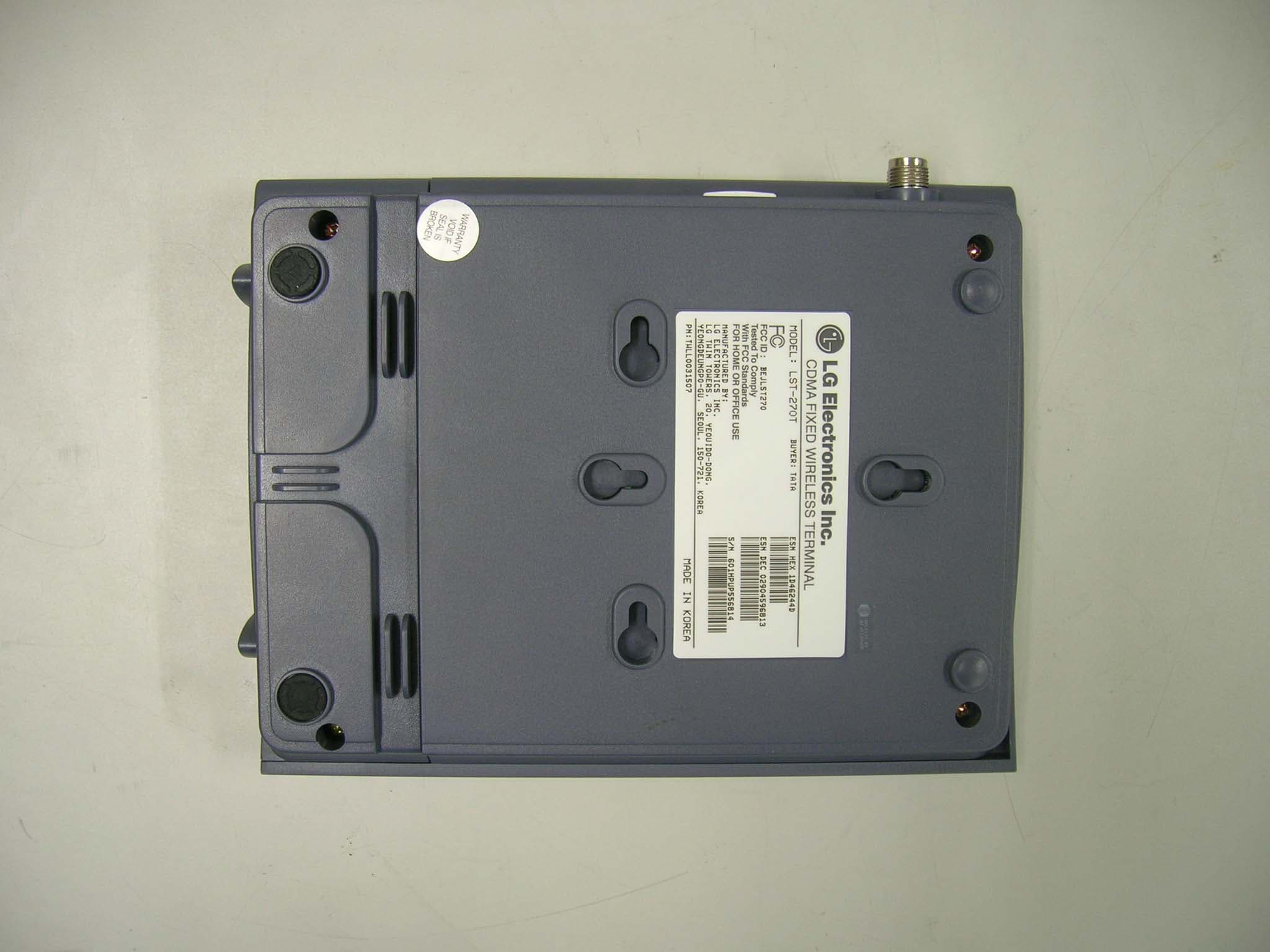
Click to zoom
Application Details
- Equipment Class
- TNB - Licensed Non-Broadcast Station Transmitter
- Date of Grant
- Mar 06, 2006
- Application Purpose
- Original Equipment
- Date of Application
- Mar 05, 2006
- Equipment Note
- Single Band, Single Mode CDMA WLL Phone
- Frequency Range
- 824.70000000 - 848.31000000
- Company
- LG Electronics USA, Inc.
- Country
- United States
Documents & Files
Document Text
Text extracted from the exhibit documents filed with the FCC. Open a document above to read the original.
Users Manual
LST-270T USER GUIDE Please read this manual carefully before operating yourset. Retain it for future reference. LST-270T 2006.1.11 4:32 PM 페이지1 3 TEBLE OF CONTENTS 2 1.1 Safety Instruction WARNING/CAUTION To reduce the risk of fire or electric shock, do notexpose this product to rain or moisture. Do not usethis product near swimming pools or other waterbodies. IMPORTANT Before installing or operating this product read thisinformation. 1.2 Optimal Phone Performance▶ Do not operate your product when holding theantenna, or when someone is within four inches(ten centimeters) of the antenna. Holding theantenna affects call quality and may cause thetelephone to operate at a higher power level thanneeded. ▶ For the best call quality, keep the antenna free fromobstructions and position the antenna straight up. ▶ Do not use the phone with a damaged antenna.Have your antenna replaced by a qualifiedtechnician immediately. Use only the AuthorizedLGE Service Center-approved antenna. Non- approved antennas, modifications, or attachmentscould impair call quality, damage the phone. ▶ RF energy may affect improperly installed orinadequately shielded personal medical devicessuch as pace makers, hospital monitor. Consult themanufacturer of any personal medical devices todetermine if they are adequately shielded fromexternal RF energy. Turn your terminal OFF inhealth care facilities when any regulations posted inthe areas instruct you to do so. Hospitals or health care facilities may be usingequipment that could be sensitive to external RFenergy. ▶ If this equipment does cause harmful interferenceto radio or television reception, which can bedetermined by turning the equipment off and on,the user is encouraged to try to correct theinterference by one or more of the followingmeasures: - Reorient or relocate the receiving antenna.- Increase the distance between the radio or television and the telephone. - Connect the equipment into an outlet on a circuit different from that to which the terminal isconnected. - Consult your experienced radio/TV technician of Before You Start 3 1.1 Safety Instruction 3 1.2 Optimal Phone Performance 3 1.3 Care and Service 4 1.4 Safety Information 5 Introduction 9 2.1 Component List 9 2.2 Front, Side and Rear View of the Terminal 10 2.3 3 LEDs Indicators 12 2.4 Installation 13 2.5 Installation Steps 16 Basic Operation 17 3.1 Power On 17 3.2 Placing a Call 17 3.3 Receiving a Call 18 3.4 Ending a Call 18 3.5 Warning Tone after Remote Disconnect 18 3.6 Emergency Call 18 3.7 Power Off 18 System Features 19 4.1 Hook Flash 19 4.2 ROH (Receiver Off Hook) 19 4.3 System Features 19 4.4 Applications 20 Programming 21 5.1 Speed Dial 21 5.2 Emergency Call 22 5.3 Hot Line 23 5.4 Alarm 24 5.5 Volume Level 25 5.6 Outgoing Call Lock 26 5.7 Restrict Call Mode Setting 26 Troubleshooting 29 General Information 30 LIMITED WARRANTY STATEMENT 32 Appendix FCC RF Exposure Information 35TATA Service Center List 36 Before You Start Before You Start T able of Contents LST-270T 2006.1.11 4:32 PM 페이지2 Before You Start 5 Before You Start 4 1.4 Safety Information WW AA RR NN II NN GG ▶ Do not use harsh chemicals,cleaning solvents, or strongdetergents to clean it. Wipe itwith a soft cloth that has beenslightly dampened in a mild soap-and water solution. ▶ Do not paint it. Paint can clog thedevice’s moving parts andprevent proper operation. ▶ During lightning, do not touchpower plug or phone line. It maycause an electric shock or death. CC AA UU TT II OO NN ▶ Do not use with car battery. Itmay cause an electric shock, fire,breakdown or transformation. ▶ For safety use, use only adapterapproved by LG. To all problems arising from notfollowing this guide, LG doesnot bear responsibility. ▶ Avoid exposure to hightemperature or humidity. Avoid wetting the unit with anyliquids. If the unit gets wet, turnthe power off immediately andremove the backup battery andAC power supply. ▶ Keep it dry. Precipitation,humidity, and liquids containminerals that may corrodeelectronic circuits. ▶ Do not use or store it in dusty,dirty areas as its moving partscan be damaged. ▶ Do not store it in hot areas.High temperatures can shortenthe life of electronic devices,damage batteries, and warp ormelt certain plastics. the Authorized LGE Service Center ▶ Use only the battery, antenna and AC power supplyprovided by LGE. Using any other type will invalidate the warranty. ▶ Only authorized personnel should service thephone and its accessories. Faulty installation or service can be dangerous andmay invalidate the warranty. ▶ Do not use the phone in designated °∞no cellularphone use°± area. Avoid exposure to high temperature or humidity. ▶ Avoid wetting the phone with any liquids. If thephone gets wet, turn the power off immediately andremove the backup battery and AC power supply. If the phone is inoperable, then return to theservice agent for service. ▶ Avoid shock or impact. ▶ We recommend you to charge the backup batterybefore initial use. Backup battery may bedischarged during delivery. ▶ This phone complies with part 15 of the FCC Rules. Operation is subject to the following twoconditions: - This phone may not cause harmful interference, and - This phone must accept any interference received, including interference that may causeundesired operation. 1.3 Care and Service▶ Unplug the telephone from the wall outlet andremove antenna (or disconnect antenna cable)before cleaning. Do not use liquid or aerosolcleaners. Use a damp cloth for cleaning. ▶ If the phone fails for any reason, do not attempt todisassemble; contact the Authorized LGE ServiceCenter for assistance. ▶ If any of the following conditions exist: unplug thephone at the wall plug, remove battery, and call theservice provider. - The power supply cord is damaged or frayed.- Liquid has been spilled into the phone.- The phone has been exposed to rain or water.- The phone has been dropped or damaged.- The phone does not work normally by followingthe operating instructions. Before Yo…
Text truncated - open the document above for the full version.
Cover Letter(s)
Feb 6. 2006 Federal Communication Commission Equipment Authorization Branch 7435 Oakland Mills Road Columbia, MID 21046 In re : LG Electronics Inc.. FCC ID: BEJLST270 SingleBand, SingleMode CDMA WLL Phone Part 22Certification Request for Confidentiality Gentlemen: In accordance with 0.459 of CFR 47, LG Electronics, Inc. hereby requests confidentiality of the Block Diagrams attachment, Schematic Diagrams & Circuit Description attachment, Operational Description attachment, and Parts List/Tune-Up Procedure attachment for the above-referenced Type Acceptance application. These documents contain detailed system and equipment description and related information about the product which LG Electronics Inc. Considers to be proprietary, confidential, and a custom design and, otherwise, would not release to the general public. Since this design is a basis from which future technological products will evolve, LG Electronics Inc. considers this information to be of benefit to its competitors, such that the disclosure of the information in these documents would give competitors an unfair advantage in the market. Sincerely, Kyeom-Soon Kim General Manager Q & R Center LG Electronics Inc. Tel : 82- 2- 2630- 3090~4 Fax : 82- 2- 2630- 3504 [email protected] LG Electronics Inc. Q & R Center, 36, Munlae-dong, 6-ga, Youngdungpo-gu, Seoul, Korea LG Electronics Inc. LGE
Cover Letter(s)
American Telecommunications Certification Body Inc. 6731 Whittier Ave, McLean, VA 22101 March 2, 2006 RE: FCC ID: BEJLST270_ATCB003221 Attention: Jay Kim I have a few comments on this Application. Please note that further comments may arise in response to answers provided to the questions below. 1. Please note that the equipment code for this type device should be TNB and not TNE. TNE would be a device held to the ear while TNB would be a mobile device. As this is a mobile device, pleae correct the 731 form to show TNB on the 731. 2. Please note that as this is a mobile device with a ‘removable’ antenna connection, the power listed on the grant would typically be the conducted power not the ERP power. Please note that the conducted power that should be on the 731 is 252mW. Please correct the 731 to be in line with this type device. Dennis Ward mailto:[email protected] The items indicated above must be submitted before processing can continue on the above referenced application. Failure to provide the requested information may result in application termination. Correspondence should be considered part of the permanent submission and may be viewed from the Internet after a Grant of Equipment Authorization is issued. Please do not respond to this correspondence using the email reply button. In order for your response to be processed expeditiously, you must submit your documents through the AmericanTCB.com website. Also, please note that partial responses increase processing time and should not be submitted. Any questions about the content of this correspondence should be directed to the sender.
ID Label/Location Info
FCC ID: BEJLST270 CDMA FIXED WIRELESS TERMINAL LG Electronics Inc.
RF Exposure Info
RF Exposure Measurement 1. Introduction The maximum Gain measured in Fully Anechoic Chamber is 2.29dBi or 1.694 (numeric). 2. Classification MODE: CDMA 3. RF Exposure Limit Magnetic Field Strength(A/m) Power Density (mW/cm 2 ) Average Time (minutes) 0.1631.06 F/3006 56 Magnetic Field Strength(A/m) Power Density (mW/cm 2 ) Average Time (minutes) 0.0730.230 F/150030 1.030 F = Frequency in MHz 1500 - 100,000 27.5 Frequency Range (MHz) Electric Field Strength (V/m) 30 - 300 300 - 1500 61.4 LIMITS FOR MAXIMUM PERMISSIBLE EXPOSURE (MPE) - Class B Because this deivce is transmitting the high power signal, it is regarded specially as a dangerous band for its heating harmfulness to the human body. The manufacturer whose product is working in this frequency band is obligatory to prove the harmfulness of his product. In this document, we try to prove the safety of radiation harmfulness to the human body for our product. The limit for Maximum Permissible Exposure (MPE) specified in FCC 1.1310 is followed. The Gain of the antenna used in this product is measured in a Fully Anechoic Chamber (FAC), and the maximum total power input to the antenna is measured. Through the Friis transmission formula and the maximum gain of the antenna, we can calculate the distance, away from the product, Page 1 of 3 The antenna of the product, under normal use condition, is at least 20cm away from the body of the user. Warning statement for kee ping 20cm separation distance and the prohibition of operating next to a person has been printed on the user's manual. So, this product is classified as the Mobile Device. According to FCC 1.1310: The criteria listed in the following table shall be used to evaluate the environmental impact of human exposure to radio-frequency(RF) radiation as specified in 1.1307(b). LIMITS FOR MAXIMUM PERMISSIBLE EXPOSURE (MPE) - Class A Frequency Range (MHz) Electric Field Strength (V/m) 30 - 300 300 - 1500 1500 - 100,000 4. Friis Formula Friis transmission formula : P d = (P out *G) / (4*π*r 2 ) The maximum Gain measured in Fully Anechoic Chamber is 2.29dBi or 1.694 (numeric). P out = output power to antenna in mW G = gain of antenna in linear scale Pi = 3.1416 MODE: CDMA Page 2 of 3 The software provided by Manufacturer enabled the EUT to transmit with max power at lowest, middle and highest channel individually. Pd is the limit of MPE, 1mW/cm 2 . If we know the maximum Gain of the antenna and the total power input to the antenna, through the calculation, we will know the distance r where the MPE limit is reached. 6. Test Results 6.1 Antenna Gain The maximum Gain measured in Fully Anechoic Chamber is 1.88dBi or 1.694 (numeric). 6.2 Output Power into Antenna & RF Exposure value at distance 20cm: MODE: CDMA Channel Channel Frequency (MHz) Output Power to Antenna (mW) Power Density (mW/cm 2 ) Limit of Power Density (mW/cm 2 ) 1013824.70211.8360.071391.0 363835.89356.4510.120131.0 777848.31414.9540.139841.0 Page 3 of 3 The minimum allowable distance is very close to the enclosure of the antenna and is very far away from the human beign under normal use condition.
Test Report
Product Name Model Name Applicant FCC ID LST-270, LST-270T, LST-270R LG Electronics Inc. BEJLST270 ESTECH CO., LTD Rm. 1015 World Venture Center, 426-5 Gasan-dong, Geumcheon-gu, Seoul, 153-803, Korea. Tel:82-2-867-3201, Fax:82-2-867-3204 ͑͑ESTECH CO., LTD. http://www.estech.co.kr FCC TEST REPORT CDMA Fixed Wireless Telephone Report Number : ESTR0602-0131 of 18 FCC ID : BEJLST270 Company Name Address Product Name Model No.Manufacturer Serial No. Country of origin Issued DateTested Date ͑͑ESTECH CO., LTD. http://www.estech.co.kr Rm. 1015 World Venture Center, 426-5 Gasan-dong, Geumcheon-gu, Seoul, 153-803, Korea. Tel:82-2-867-3201, Fax:82-2-867-3204 ESTECH CO., LTD FCC Test Report Applicant Product Report Number LST-270, LST-270T, LST-270R KOREA LG Electronics Inc. o This is certified that the above mentioned products have been tested for the sample provided by client. o No part of this document may not be duplicated or reproduced by any means without the express written permission of Estech Co., Ltd. Standard FCC PART 22 Subpart H Tested by Approved by S.R. Kim/ Engineer (Signature) Jay Kim/ Engineering Manager (Signature) ESTR0602-013 459-9, Kasan-dong, Keumchun-ku, Seoul 153-023, Korea CDMA Fixed Wireless Telephone NONE LG Electronics Inc. Test Result Pass 2006-02-24 2005-1-16 ~ 2006-2-24 Other Report Number : ESTR0602-0132 of 18 FCC ID : BEJLST270 1. General Information Page 4 2. Laboratory Information Page 5 3. Summary of Test Results Page 5 4. RF Output Power Page 6 5. Occupied Bandwidth Page 8 6. Spurious and Harmonic Emission at Antenna Terminal Page 10 7. Field Strength of Spurious Radiation Page 15 8. Frequency stability Page 17 Contents ͑͑ESTECH CO., LTD. http://www.estech.co.kr Report Number : ESTR0602-0133 of 18 FCC ID : BEJLST270 1. General Information 1.1 EUT Description Channel Tx :824.70 ~ 848.31MHz CDMA (1013/363/777) CDMA Frequency Rx :869.70 ~ 893.31MHz 3.7VDC(3.2 ~ 4.3VDC) Power Rating ͑͑ ESTECH CO., LTD. http://www.estech.co.kr FCC ID BEJLST270 Modulation Type Product Name Model Name CDMA Fixed Wireless Telephone LST-270, LST-270T, LST-270R Report Number : ESTR0602-0134 of 18 FCC ID : BEJLST270 2. Laboratory Information 3. Summary of Test Results Result PASS PASS PASS PASS ͑͑ ESTECH CO., LTD. http://www.estech.co.kr 58-1, Osan-Ri, GaNam-Myon, YeoJoo-Gun, KyungKi-Do, Korea 97-1, Hoiuk-Ri Majang-Myon, Icheon-city, KyungKi-Do, Korea 2.4 Major Accredited Mark Test Item Accredited by KOLAS(ISO/IEC 17025) Head Office EMC Lab(Ichon) EMC Lab(Yanggi) Standard RF Output Power Occupied Bandwidth PASS 2.1 Laboratory Name 2.2 Location 2.3 Quality System Estech Co., Ltd. Rm. 1015, World Venture Center II, 426-5 Gasan-dong Geumcheon-gu, Seoul, 153-803. Korea. Part 22 Field Strength of Spurious Radiation Frequency stability Spurious and Harmonic Emission at Antenna Terminal Report Number : ESTR0602-0135 of 18 FCC ID : BEJLST270 4. RF Output Power 4.1 Test Procedure 4.2 Test Equipments The following test equipments are used during tests 4.3. Test Results 1013824.70 363835.89 777848.31 24.02 24.02 25.52 26.18 310N BBHA 9120 D BBHA 9120 D SONOMA INSTRUMENT SCHWARZBECK SCHWARZBECK Ch No.Freq (MHz) 24.0023.26 Peak Power Meter(dBm)Peak Power ERP(dBm) Pre Amplifier Horn Antenna Horn Antenna Agilent Wireless Communications Test Set E5515C Model ESP17 HP HP Manufacturer Rohde & Schwarz ͑͑ ESTECH CO., LTD. http://www.estech.co.kr Signal Generator Power Meter 83620B EPM-442A Equipment Receiver The EUT was placed on a wooden turn table 3 meters from the receive antenna. The receive antenna height and turn table rotation was adjusted for the highest reading on the receive spectrum analyzer. For CDMA signals, a peak detector is used, with RBW = VBW = 3MHz. For AMPS, GSM, and NADC TDMA signals, a peak detector is used, with RBW = VBW = 1MHz, A Horn antenna was substituted in place of the EUT. This Horn antenna was driven by a signal generator and the level of the signal generator was adjusted to obtain the same receive spectrum analyzer reading. This spurious level is recorded. For reading 1GHz, the above procedure is repeated using horn antennas and the difference between the gain of the horn and an isotropic or dipole antenna are taken into consideration. Report Number : ESTR0602-0136 of 18 FCC ID : BEJLST270 Antenna gain(dBi) Cable Loss (dB) 824.70 97.173.15 3.3023.4123.2638.5V 835.89 100.833.45 3.3025.3725.5238.5V 848.31 101.333.75 3.3025.7326.1838.5V ͑͑ ESTECH CO., LTD. http://www.estech.co.kr FREQ (MHz) Correction Factor (dB) POL (H/V) Limit (dBm) ERP (dBm) SG Reading (dBm) Receiver Reading (dBuV) Report Number : ESTR0602-0137 of 18 FCC ID : BEJLST270 5. Occupied Bandwidth 5.1 Test Procedure 5.2 Test Equipments The following test equipments are used during tests 5.3 Test Results The transmitter output is connected to the spectrum analyzer. The RBW is set to 1% of the Emission bandwidth. The VBW is set to 3 times the RBW. The sweep time is coupled. 777848.311.396 E5515C 363835.891.397 ChannelFrequency(MHz) Manufacturer Agilent HP ͑͑ ESTECH CO., LTD. http://www.estech.co.kr Dual Directional Coupler EquipmentModel E4407B 778D 1013824.701.396 Spectrum Analyzer Wireless Communications Test Set Agilent 26dB Bandwidth(MHz) Report Number : ESTR0602-0138 of 18 FCC ID : BEJLST270 5.4 Test Plot 26dB Channel Bandwidith(1013) 26dB Channel Bandwidith(363) 26dB Channel Bandwidith(777) ͑͑ESTECH CO., LTD. http://www.estech.co.kr Report Number : ESTR0602-0139 of 18 FCC ID : BEJLST270 6. Spurious and Harmonic Emission at Antenna Terminal 6.1 Test Procedure 6.2 Test Equipments The following test equipments are used during tests 6.3 Test Results CDMA (Spurious Emission: Band Edge) ChannelFrequencyResultLimitMargin 1013824.70-14.25-13.001.25 777848.31-15.14-13.002.14 CDMA (Spurious Emission: Out of Band) ChannelFrequencyResultLimitMargin 1013824.70-25.43-13.0012.43 363835.89-27.13-13.0014.13 777848.31-21.33-13.008.33 Spectrum Analyzer Manufacturer Agilent E5515C HP ͑͑ ESTECH CO., LTD. http://www.estech.co.kr Dual …
Text truncated - open the document above for the full version.
Contact Information
Applicant
David Kim(Team leader, LGEUS NA Policy & Regulatory Affairs)
Technical Specifications
| # | Rule Parts | Frequency Range | Power Output | Emission | Tolerance |
|---|---|---|---|---|---|
| 1 | 22H | 824.7 MHz - 848.31 MHz | 252.00 mW | 1M25F9W | 2.5000000000 ppm |
Other Applications from LG Electronics USA, Inc.

BEJTFHOBINI1F1
Jan 08, 2025Telematics
Equipment Class
DTS - Digital Transmission SystemBEJNT-16Z90TS
Oct 02, 2024Notebook Computer
Equipment Class
DSS - Part 15 Spread Spectrum TransmitterBEJSP-PEW8
Sep 26, 2024Stylus Pen
Equipment Class
DCD - Part 15 Low Power Transmitter Below 1705 kHzBEJ-RSMV2
Sep 24, 2024RF Module
Equipment Class
FDS - Part 15 Field Disturbance SensorBEJTFBMEIBN3EU
Sep 24, 2024Telematics
Equipment Class
NII - Unlicensed National Information Infrastructure TX