BEJLT-N050GPTri Mode Quad Band Phone System
LG Electronics USA, Inc.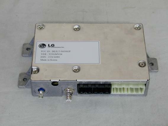
Click to zoom
Application Details
- Equipment Class
- PCB - PCS Licensed Transmitter
- Date of Grant
- Oct 28, 2004
- Application Purpose
- Original Equipment
- Date of Application
- Oct 28, 2004
- Equipment Note
- Tri Mode Quad Band Phone System
- Frequency Range
- 1851.25000000 - 1908.75000000
- Company
- LG Electronics USA, Inc.
- Country
- United States
Documents & Files
Document Text
Text extracted from the exhibit documents filed with the FCC. Open a document above to read the original.
Users Manual
TABLE OF CONTENTS ACTIVATING ONSTAR SERVICES..................................................................................................3 ONSTAR.................................................................................................................................................4 THE ONSTAR CALL CENTER......................................................................................................4 YOUR ONBOARD ONSTAR PANEL............................................................................................4 VOLUME CONTROL......................................................................................................................5 ADVISOR PLAYBACK...................................................................................................................5 STEERING-WHEEL CONTROLS.................................................................................................6 CONTACTING ONSTAR................................................................................................................9 CONTACTING ONSTAR FOR SERVICES .................................................................................9 CONTACTING ONSTAR CUSTOMER CARE OR BILLING/FINANCIAL..............................9 PERSONAL IDENTIFICATION NUMBER (PIN)............................................................................9 ONSTAR SERVICES..........................................................................................................................10 AUTOMATIC NOTIFICATION OF AIR BAG DEPLOYMENT.............................................10 EMERGENCY SERVICES............................................................................................................10 ROADSIDE ASSISTANCE*..........................................................................................................10 STOLEN VEHICLE LOCATION.................................................................................................10 ACCIDENTASSIST........................................................................................................................10 REMOTE DOOR UNLOCK..........................................................................................................11 REMOTE DIAGNOSTICS**.........................................................................................................11 ROUTE SUPPORT.........................................................................................................................11 RIDEASSIST...................................................................................................................................11 INFORMATION AND CONVINIENCE SERVICES.................................................................11 ONSTAR CONCIERGE.................................................................................................................11 ONSTAR PERSONAL CALLING.....................................................................................................11 ACTIVATING ONSTAR PERSONAL CALLING......................................................................12 PERSONAL CALLING UNIVERSAL COMMANDS................................................................12 PLACING A CALL.........................................................................................................................12 RECEIVING A CALL....................................................................................................................13 ENDING A CALL...........................................................................................................................13 STORING/DELETING NUMBERS IN MEMORY (NAMETAGS)..........................................13 VERIFY REMAINING UNITS (MINUTES)...............................................................................14 ADDING MORE CALLING UNITS (MINUTES).......................................................................14 RETRIEVING YOUR NUMBER..................................................................................................15 SECURITY/LOCKING YOUR SYSTEM....................................................................................15 ONSTAR VIRTUAL ADVISOR.........................................................................................................15 ACCESSING VIRTUAL ADVISOR.............................................................................................16 GETTING INFORMATION FROM VIRTUAL ADVISOR......................................................16 INFORMATION CATEGORIES..................................................................................................16 TRAFFIC* ....................................................................................................................................17 WEATHER ...................................................................................................................................17 NEWS ...........................................................................................................................................17 FINANCIAL SERVICES .............................................................................................................17 EMAIL..........................................................................................................................................17 SPORTS........................................................................................................................................17 ENTERTAINMENT/HOROSCOPE ............................................................................................17 ONSTAR.COM – YOUR PERSONALIZED WEB SITE................................................................18 ONSTAR.COM................................................................................................................................18 VOICE COMMANDS/SPEECH RECOGNITION..........................................................................18 PER…
Text truncated - open the document above for the full version.
Cover Letter(s)
AFFIDAVIT FOR ESN PROTECTION OF CELLULAR MOBILE TELEPHONES We hereby certify that the LGE Handheld Portable Cellular Telephone(FCC ID: BEJLT-N050GP) is so designed that it complies with all the requirements for ESN protection specified in section 22.919 of the FCC Rules. A) The transmitter in service has a unique ESN. B) The ESN host component is permanently attached to a main circuit board of the mobile transmitter and the integrity of the unit operating software cannot be altered. The ESN is plated from fraudulent contact and tampering. The ESN is encoded using multiplication by a polynomial and the ESN data programmed in the memory with other information. C) The ESN is factory-set and cannot be altered, transferred, removed or otherwise able to be manipulated. Cellular mobile equipment is specifically designed such that any attempt to remove, tamper with, or change the ESN chip, its logic system, or firmware originally programmed by the manufacturer will render the mobile transmitter inoperative. Sincerely, E.S.Park Chief Research Engineer CDMA Handset Lab LG Electronics Inc. Tel : 82-2-850-3850 Fax : 82-2-850-3861 [email protected] 459-9, Kasan-dong,Kemchun-ku Seoul 153-023, Korea LG Electronics Inc. LGE Tel : 82-2-850-3850 Fax : 82-2-850-3861 [email protected] 459-9, Kasan-dong,Kemchun-ku Seoul 153-023, Korea LG Electronics Inc. LGE Sep 13. 2004 Federal Communication Commission Equipment Authorization Branch 7435 Oakland Mills Road Columbia, MID 21046 Subject : LG Electronics Inc.. FCC ID: BEJLT-N050GP FCC E911 Requirements Per 522.921 Gentlemen: LG Electronics, Inc. hereby certifies that the analog cellular telephone(FCC ID : BEJBD6070), using the Automatic A/B Roaming–intelligent Retry method, meets the E911 requirements specified in Section 522.921 of the FCC Rules, This procedure recognizes when a “9-1-1” call is made and, at such time, will override any programming in the mobile unit that determines the handling of a non-911 call and permit the call to he handled by other analog carriers. Should you any have questions or comments concerned the above, please contact the undersined. Sincerely, E.S.Park Chief Research Engineer CDMA Handset Lab LG Electronics Inc.
Cover Letter(s)
Sep 13. 2004 Federal Communication Commission Equipment Authorization Branch 7435 Oakland Mills Road Columbia, MID 21046 In re : LG Electronics Inc.. FCC ID: BEJLT-N050GP Tri Band Quad - Mode Cellular Phone (CDMA) Part 22, 24 Certification Request for Confidentiality Gentlemen: In accordance with 0.459 of CFR 47, LG Electronics, Inc. hereby requests confidentiality of the Block Diagram, Schematic Diagrams, Operational Description, Technical Specification, Parts List, and Tune-Up Procedure for the above-referenced certification application. These documents contain detailed system and equipment description and related information about the product which LG Electronics Inc. Considers to be proprietary, confidential, and a custom design and, otherwise, would not release to the general public. Since this design is a basis from which future technological products will evolve, LG Electronics Inc. considers this information to be of benefit to its competitors, such that the disclosure of the information in these documents would give competitors an unfair advantage in the market. Sincerely, E.S.Park Chief Research Engineer CDMA Handset Lab LG Electronics Inc. Tel : 82- 2- 850-3850 Fax : 82- 2- 850-3855 [email protected] 459- 9, Kasan-dong,Kemchun-ku Seoul 153- 023, Korea LG Electronics Inc. LGE
ID Label/Location Info
- Label drawing Model No . LT - N050GP FCC ID : BEJLT - N050GP S/N : Made in Korea LG Electronics Inc. LGE
Operational Description
NAD LG Electronics Inc. Features of LT-N050GP 1. Wave Type • AMPS : F3E/F9X • CELLULAR : G7W • PCS : G7W 2. Frequency Scope Transmit Frequency (MHz) Receive Frequency (MHz) AMPS CELLULAR PCS AMPS CELLULAR PCS GPS 824.04 ~ 848.97 824.82 ~ 848.19 1850~1910 869.04~893.97 869.82~893.19 1930~1990 1575.42 3. Rated Output Power : AMPS = 3W CELLULAR = 0.251W PCS = 0.251W 4. Output Conversion Method : This is possible by correcting the key Modem channel. 5. Voltage and Current Value of Termination Part Amplifier (Catalogue included) MODE Part Name Voltage Current Power AMPS AWT6112 12V 1700mA 3.000W CELLULAR AWT6112 12V 450mA 0.251W PCS AWT6135 12V 450mA 0.251W 6. Functions of Major Semi-Conductors Classification Function MSM6050-FBGA Terminal operation control and digital signal processing Memory Flash Memory (32Mbit)---MX29LW320TXBI-70 S-RAM (16Mbit)---EM566168 RFR6000 Converts RF signal to baseband signal RFT6100 Converts baseband signal to RF signal 7. Frequency Stability • CELLULAR : ± 0.5PPM • AMPS : ± 2.5PPM • PCS : ± 0.1PPM NAD LG Electronics Inc. - 2 - CDMA Mobile Subscriber Unit LT-N050GP TRI BAND, QUAD MODE [PCS/GPS/CELLULAR/AMPS] CDMA MOBILE MODEM SERVICE MANUAL NAD LG Electronics Inc. - 3 - Table of Contents General Introduction ............................................................................................................................................................. 4 CHAPTER 1. System Introduction 1. System Introduction..............................................................................5 2. Features and Advantages of CDMA Mobile Modem (For AMPS as well)..............6 3. Structure and Functions of dual-band CDMA Mobile Modem...........................8 4. Specification.......................................................................................10 5. Installation........................................................................................18 CHPATER 2. NAM Input Method 1. NAM Program Method and TeleModem Number Inputting Method..................20 CHAPTER 3. Circuit Description 1. RF Transmit/Receive Part......................................................................183 2. Digital/Voice Processing Part..................................................................30 CHAPTER 4. Safety....................................................................................35 CHAPTER 5. Glossary.................................................................................38 APPENDIX................................................................................................51 NAD LG Electronics Inc. - 4 - The LT-N050GP has been designed to operate on the latest digital mobile communication technology, Code Division Multiple Access (CDMA). This CDMA digital technology has greatly enhanced voice clarity and can provide a variety of advanced features. Currently, CDMA mobile communication technology has been commercially used in Cellular and Personal Communication Service (PCS). The difference between them is the operating frequency spectrum. Cellular uses 800Mhz and PCS uses 1.9Ghz. The LT-N050GP support GPS Mode, we usually call it tri-band Modem. Also, LT-N050GP works on Advanced Mobile Modem Service (AMPS). We call it quad-mode Modem. If one of the Cellular, PCS and AMPS base stations is located nearby, Call fail rate of triple-mode Modem is less than dual-mode Modem or single-mode Modem. The CDMA technology adopts DSSS (Direct Sequence Spread Spectrum). This feature of DSSS enables the Modem to keep communication from being crossed and to use one frequency channel by multiple users in the same specific area, resulting that it increases the capacity 10 times more compared with that in the analog mode currently used. Soft/Softer Handoff, Hard Handoff, and Dynamic RF power Control technologies are combined into this Modem to reduce the call being interrupted in a middle of talking over the Modem. Cellular and PCS CDMA network consists of MSO (Mobile Switching Office), BSC (Base Station Controller), BTS (Base station Transmission System), and MS (Mobile Station). The following table lists some major CDMA Standards. CDMA Standard Designator Description Basic air interface TIA/EIA/IS-95-A/B/C ANSI J-STD-008 Protocol between MS and BTS for Cellular & AMPS Protocol between MS and BTS for PCS Network TIA/EIA/IS-634 TIA/EIA/IS/651 TIA/EIA/IS-41-C TIA/EIA/IS-124 MAS-BS PCSC-RS Intersystem operations Nom-signaling data comm. Service TIA/EIA/IS-96-B TIA/EIA/IS-99 TIA/EIA/IS-637 TIA/EIA/IS-657 Speech CODEC Assign data and fax Short message service Packet data Performance TIA/EIA/IS-97 TIA/EIA/IS-98 ANSI J-STD-018 ANSI J-STD-019 TIA/EIA/IS-125 Cellular base station Cellular mobile station PCS personal station PCS base station Speech CODEC * TSB –74: Protocol between an IS-95A system and ANSI J-STD-008 CHAPTER 1.General Introduction NAD LG Electronics Inc. - 5 - 1. System Introduction 1.1 CDMA Abstract The CDMA mobile communication system has a channel hand-off function that is used for collecting the information on the locations and movements of mobile teleModems from the cell site by automatically controlling several cell site through the setup of data transmission routes, and then enabling one switching system to carry out the automatic remote adjustment. This is to maintain continuously the call state through the automatic location confirmation and automatic radio channel conversion when the busy subscriber moves from the service area of one cell site to that of another by using automatic location confirmation and automatic radio channel conversion functions. The call state can be maintained continuously by the information exchange between switching systems when the busy subscriber moves from one cellular system area to the other cellular system area. In the cellular system, the cell site is a small-sized low output type and utilizes a frequency allocation system that considers mutual interference, in an effort to enable the re-use of corr…
Text truncated - open the document above for the full version.
RF Exposure Info
Sep 13. 2004 Federal Communication Commission Equipment Authorization Branch 7435 Oakland Mills Road Columbia, MID 21046 SAR Test Report for LG Electronics Cellular Phone FCC ID BEJLT-N050GP. The LG Electronics Mobile Handset R&D Center has evaluated the mobile cellular phone, FCC ID BEJLT-N050GP, for the need to conduct SAR evaluation. Due to the design and installation of this product, it is not possible to conduct SAR evaluation. This is because LG Electronics neither manufactures or supplies the antenna(s) that will be used in the installation of this product. Therefore, this product will be evaluated as a mobile device per47 CFR 1.1310 titled “Radiofrequency radiation exposure limits”, generally referred to as MPE limits. In 47 CFR 2.1091, paragraph (b) defines a mobile device as “a transmitting device designed to be used in other than fixed locations and to generally be used in such a way that a separation distance of at least 20 centimeters is normally maintained between the transmitter’s radiating structure(s) and the body of the user or nearby persons.”This product is intended to be installed into a vehicle such that the unit is physically secured at one location. In the installation guide supplied with the product, LG Electronics has made the followingstatement: “IMPORTANT: To meet the FCC’s RF Exposure Guidelines, the antenna should be installed so there is at least 20 cm of separation between the body of the user and nearby personsand the antenna”. Based on the installation of the transceiver and the antenna, the transmitters radiating structure is more than 20 centimeters from the user. Thus, this product is a “mobile device”as defined in section 2.1091 paragraph (b). Table 1 (B) of 47 CFR 1.1310 lists the limits for MPE for the General Population. Since the mobile cellular phone operates in the 800 MHz cellular band and 1900MHz PCS band, the listed limit of f/1500 applies. The lowest transmit frequency for this product is 824.04 MHz, resulting in a MPE limit of 0.549 mW/cm2. Since LG Electronics neither manufactures or supplies the antenna(s) that will be used in the installation of this product, it is not possible to measure the MPE of the actual device as it is installed per the installationmanual. Therefore a calculation of MPE will be described in the next paragraph. Tel : 82-2-850-3850 Fax : 82-2-850-3861 [email protected] 459-9, Kasan-dong, Kemchun-ku Seoul 153-023, Korea LG Electronics Inc. LGE The MPE of a radiating structure can be calculated by knowing the transmit EIRP and the distance at which MPE is being calculated. In this case MPE willbe calculated at 20 cm, which is the minimum separation between the body of the user and nearby persons and the antenna. The maximum transmit power for this product is 3.0 Watts in the Analog mode and 0.27 Watts in the CDMA mode. When installed using a combined cable loss and antenna gain of a maximum of - 1.7 dBi(at 800MHz), the maximum EIRP will be 2.0 Watts. The model usedfor calculating power density in OET Bulletin 65, Edition 97-01, is the spherical model. Using this spherical model, 0.404mW/cm2 is achieved at a distance of 20cm from the antenna at 800MHz. At 1900MHz the power density is lower because of the lower transmitpower. Therefore, by requiring the user and nearby persons to remain at least 20cm from the antenna, the MPE is not exceeded. Sincerely, E.S.Park Research Engineer CDMA Handset Lab LG Electronics Inc.
Test Report
Report Number: ESTR0409-009 Dates: September 22, 2004 Page 1 of 42 FCC ID: BEJLT-N050GP EUT Type: Tri-mode Quad Band AMPS/PCS/DCN/GPS Phone System Test Report Report Number ESTR0409-009 Company Name LG Electronics Inc. Address 459-9, Kasan-dong, Keumchun-ku, Seoul 153-023, Korea Applicant Telephone 82-31-789-4246 Product Name Telematics Terminal Model No. LT-N050GP Manufacturer LG Electronics Inc. Serial No. NONE Country of origin Korea Product Date of Receipt 2004-09-22 Date of Test 2004-09-15 ~2004-9-21 Testing Lab. ESTECH. Co., Ltd Standard FCC PART 22 and 24 Tested by S.R. Kim/ Engineer (Signature) Approved by Jay Kim/ Manager Engineer (Signature) * Note - This test report is not permitted to copy partly without our permission - This test result is dependent on only equipment to be used - This test result based on a single evaluation of one sample of the above mentioned Report Number: ESTR0409-009 Dates: September 22, 2004 Page 2 of 42 FCC ID: BEJLT-N050GP EUT Type: Tri-mode Quad Band AMPS/PCS/DCN/GPS Phone System TABLE OF CONTENTS ATTACHMENT: TEST RESULT CERTIFICATION............................ 1 1. INTRODUCTION.....................................................................3 2. DESCRIPTION OF EUT............................................................. 4 3. DESCRIPTION OF TEST.......................................................... .. 5 4. TEST DATA 4.1 RF POWER OUTPUT (E.R.P.).................................................9 4.2 FIELD STRENGTH OF SPURIOUS RADIATION........................ 11 4.3 SPURIOUS EMISSION AT ANTENNA TERMINAL.....................18 4.4 FREQUENCY STABILITY..................................................... 20 4.5 OCCUPIED BANDWIDTH................................................22 4.5.1. Un-modulated Signal..........................................................................22 4.5.2. Signaling Tone(ST) & Supervisory Audio Tone(SAT)............................... ..23 4.5.3. Wide Band Data(WBD)..................................................................... .. 25 4.5.4. Wide Band Data(WBD)......................................................................27 5. TEST PLOTS 5.1 PLOTS OF EMISSIONS.........................................................28 5.2 MOBILE EMISSION IN BASE FREQUENCY RANGE................. 39 5.3 MODULATION CHARACTERISTICS...................................... 40 5.3.1. Modulation Limit..............................................................................40 5.3.2. Audio Frequency Response................................................................ ..41 5.3.3. Audio Low Pass Filter Response......................................................... ..42 Report Number: ESTR0409-009 Dates: September 22, 2004 Page 3 of 42 FCC ID: BEJLT-N050GP EUT Type: Tri-mode Quad Band AMPS/PCS/DCN/GPS Phone System 1. INSTROCTION 1.1 General This EUT (Equipment Under Test) has been shown to be capable of compliance with the applicable technical standards and tested in accordance with the measurement procedures as indicated in this report ESTECH Lab attests to accuracy of test data. All measurement reported herein were performed by ESTECH Co., Ltd. ESTECH Lab., assume full responsibility for the completeness of these measurements and vouch for the qualifications of all persons taking them. 1.2 Test Lab. Corporation Name: ESTECH Co. Ltd. Head Office: 3 rd Fl., Chungdam Bldg., 119-1, Chungdam-dong Kangnam-gu , Seoul, Korea (Safety & Telecom. Test Lab) EMC Test Lab. : 58-1, Osan-Ri, GaNam-Myon, YeoJoo-Gun, KyungKi-Do, Korea 97-1, Hoiuk-Ri Majang-Myon, Icheon-city, KyungKi-Do, Korea Report Number: ESTR0409-009 Dates: September 22, 2004 Page 4 of 42 FCC ID: BEJLT-N050GP EUT Type: Tri-mode Quad Band AMPS/PCS/DCN/GPS Phone System 2. Description of EUT 2.1 Summary of Equipment Under Test ♦ FCC ID : BEJLT-N050GP ♦ Freq. Range : - In CELL mode Rx : 869.820 ~ 893.190 MHz Tx : 824.820 ~ 848.190 MHz - In AMPS mode Rx : 869.64 ~ 893.37 MHz Tx : 824.64 ~ 848.37 MHz - In PCS Mode Rx : 1931.250 ~ 1988.750MHz Tx : 1851.250 ~ 1908.750MHz - In GPS Mode Rx : 1575.42MHz ♦ Power Rating : 12VDC(9 ~ 16VDC) ♦ EUT Type : Tri-mode Quad Band AMPS/PCS/DCN/GPS Phone System ♦ Modulation(s) : CDMA(PCS/DCN)-FM, GPS . Report Number: ESTR0409-009 Dates: September 22, 2004 Page 5 of 42 FCC ID: BEJLT-N050GP EUT Type: Tri-mode Quad Band AMPS/PCS/DCN/GPS Phone System 3. DESCRIPTION OF TEST 3.1 Transmitter Audio Frequency Response The frequency response of the audio modulating circuit over the frequency range 100 – 5000Hz is measured. The audio signal generator is connected to the audio input circuit/microphone of the EUT. The audio signal input is adjusted to obtain 50% modulation at 1kHz and this point is taken as the 0dB reference. With the input held constant and below the limit at all frequencies, the audio signal generator is varied from 100 to 50kHz. 3.2 Audio Low Pass Filter Frequency Response The response in dB relative to 1kHz is measured using the HP8901 a Modulation Analyzer. For the frequency response of the audio low-pass filter, the audio input is connected at the input to the modulation limiter and the modulated stage. The audio output is connected at the output of the modulated stage. The corresponding plots are shown herein. 3.3 Modulation Limiting The audio signal generator is connected to the audio input circuit/microphone of the EUT. The modulation response is measured for each of the three modulating frequencies (300Hz, 1000Hz, and 3000Hz), and the input voltage is varied from 30% modulation( ±3.6kHz deviation)to at least 20dB higher than the saturation point. Measurements of modulation and the plots are attached herein. Measurements were performed for ST, SAT, and wide- band data modulations. The corresponding results are shown herein. Fig. Transmitter Audio Frequency & Tone Modulation Test Setup EUT HP 8903B Audio Generator HP 8901A Modulation Analyzer HP 8903B Audio Analyzer ATT. OR ANT. COUPLER Report Number: ESTR0409-009 Dates: Septe…
Text truncated - open the document above for the full version.
Test Setup Photos
Report Number: ESTR0409-009 Dates: September 22, 2004 Page 1 of 2 FCC ID: BEJLT-N050GP EUT Type: Tri-mode Quad Band AMPS/PCS/DCN/GPS Phone System The Set-Up Photo of Test Report Number: ESTR0409-009 Dates: September 22, 2004 Page 2 of 2 FCC ID: BEJLT-N050GP EUT Type: Tri-mode Quad Band AMPS/PCS/DCN/GPS Phone System
Contact Information
Applicant
David Kim(Team leader, LGEUS NA Policy & Regulatory Affairs)
Technical Contact
ESTech Co., Ltd.Jay Kim
[email protected]82-2-549-0485
3rd Fl. Chungdam Bldg. 119-1 Chungdam-Dong · Seoul · South Korea
Test Firm
Estech Co., Ltd.Ike Chung
Technical Specifications
| # | Rule Parts | Frequency Range | Power Output | Emission | Tolerance |
|---|---|---|---|---|---|
| 3 | 24E | 1.85 GHz - 1.91 GHz | 250.00 mW | 1M25F9W | 2.5 ppm |
Other Applications from LG Electronics USA, Inc.

BEJTFHOBINI1F1
Jan 08, 2025Telematics
Equipment Class
DTS - Digital Transmission SystemBEJNT-16Z90TS
Oct 02, 2024Notebook Computer
Equipment Class
DSS - Part 15 Spread Spectrum TransmitterBEJSP-PEW8
Sep 26, 2024Stylus Pen
Equipment Class
DCD - Part 15 Low Power Transmitter Below 1705 kHzBEJ-RSMV2
Sep 24, 2024RF Module
Equipment Class
FDS - Part 15 Field Disturbance SensorBEJTFBMEIBN3EU
Sep 24, 2024Telematics
Equipment Class
NII - Unlicensed National Information Infrastructure TX