BEJLTGEN97LNBCellular/PCS CDMA Transceiver
LG Electronics USA, Inc.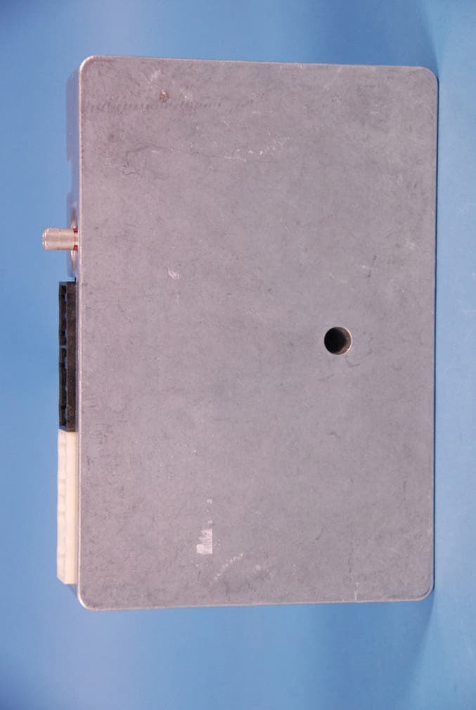
Click to zoom
Application Details
- Equipment Class
- PCB - PCS Licensed Transmitter
- Date of Grant
- Mar 24, 2011
- Application Purpose
- Original Equipment
- Date of Application
- Mar 24, 2011
- Equipment Note
- Cellular/PCS CDMA Transceiver
- Frequency Range
- 1851.25000000 - 1908.75000000
- Company
- LG Electronics USA, Inc.
- Country
- United States
Documents & Files
Document Text
Text extracted from the exhibit documents filed with the FCC. Open a document above to read the original.
Users Manual
The safety and security of OnStar ® is now yours. 16312 6.1 text R3.qxd 1/10/06 4:27 PM Page 1 Congratulations on your purchase of an OnStar-equipped vehicle. Using several innovative technologies, OnStar can provide you with the latest information and assistance when you’re on the road. Now you can enjoy the peace of mind that comes with knowing you’re doing all you can to help keep you, your family, and your vehicle safe. Take a moment to familiarize yourself with the three OnStar buttons. They are usually located on the inside rearview mirror, in the overhead console, or near the radio display. The white phone button is the Hands-Free Calling button, the blue button is the OnStar button, and the red button is the emergency button. The blue button can connect you to a specially trained OnStar Advisor 24 hours a day, 365 days a year, for assistance. A note to owners of preowned vehicles: Press the blue button now and an Advisor will explain your subscription plan options. Push the blue button now and an Advisor can help orient you with your new system. 1 Welcome. 16312 6.1 text R3.qxd 1/10/06 4:27 PM Page 2 In the event of an emergency, push the red emergency button, your vehicle is designed to send your current location to an OnStar Advisor who can find out what assistance you need, and notify nearby emergency service providers.* The system can also automatically call OnStar if your air bags deploy. But OnStar isn’t just there for you in an emergency; it’s there for you every day for the little things, too. If you accidentally lock your keys inside your car, an OnStar Advisor can send a signal to unlock your door.* And if your car is stolen, OnStar can help the police locate it.* One of the most popular features is OnStar Hands-Free Calling, that allows you to make and receive voice-activated phone calls. It’s a convenient, safer way to stay connectedwhen you’re behind the wheel. Read on and learn more about OnStar Hands-Free Calling - and start making calls today. Every new OnStar equipped-vehicle comes with 30 complimentary minutes good for 2 months - no strings attached. Be sure to use your minutes before the two month expiration. Owner Guides are available in Spanish and French languages. Visit onst ar.com. Your vehicle may be able to be programmed to respond in French or Spanish language, just press the OnStar button and ask an Advisor. Please keep this guide in your vehicle for reference.Yo u can also learn how OnStar works by listening to the enclosed audio CD. Thank you for choosing an OnStar-equipped vehicle. *OnStar services require vehicle electrical system (including battery), wireless service, and GPS satellite signals to be available and operating for features to function properly. OnStar acts as a link to existing emergency service providers. See “Additional Information” section on pages 31-38 for system limitations and details. OnStar Owner’s Guide 16312 6.1 text R3.qxd 1/10/06 4:27 PM Page 3 Blue Button Press this button now and you’ll be connected to a specially trained OnStar Advisor who can verify all of your account information and can answer any questions you may have.* •Most new OnStar-equipped vehicles come with a one-year subscription to the Safe & Sound Plan. There’s no cost to talk to a knowledgeable OnStar Advisor, it’s all a part of your OnStar service. •If your vehicle has the Directions & Connections Plan, or if you choose to upgrade your service plan, an Advisor can give you driving directions, find businesses or restaurants, assist in making reservations, and provide many other convenience services. 3 It all begins with the blue button. 16312 6.1 text R3.qxd 1/10/06 4:27 PM Page 4 Red Emergency Button In an emergency, push this button to get specialized help from OnStar Emergency Advisors. •If you are having an emergency in your vehicle. •If you are in an accident where the airbags do not deploy. •To be a good Samaritan. •To respond to an AMBER Alert situation. Phone Button We’ve made staying in touch on the road safer with Hands-Free, voice-activated calling that’s built right into your vehicle.* •Use this button to make an outgoing phone call. •To answer an incoming phone call. •To end a call. •To access Virtual Advisor for location based traffic, weather and stock reports. *OnStar services require vehicle electrical system, wireless service, and GPS satellite technologies to be available and operating. OnStar acts as a link to existing emergency service providers. See “Additional Information” section on pages 31–38 for system limitations and details. 4 16312 6.1 text R3.qxd 1/10/06 4:27 PM Page 5 5 System status On the right side of the OnStar buttons is a System Status light. Your vehicle runs an OnStar systems check every time you start up. This light is designed to indicate to you that your OnStar system is active and ready to make calls. On vehicles with an automatic dimming rearview mirror, the green light on the left side of the button indicates that the automatic dimming function is on. Solid Green- indicates the OnStar system is fully functional and ready to make or receive calls. Flashing Green- when you are in a phone call or when someone is calling you the green light will flash. Red- indicates that your OnStar system has detected a problem within the system. Press your OnStar button and ask your OnStar Advisor to run a diagnostic check. If you cannot connect to OnStar please visit a dealer as soon as possible for service. No Light- this indicates that your OnStar subscription has expired. All services have been deactivated and are not functional. Press the blue OnStar button and wait until your system connects to an Advisor who can renew your subscription. See page 31 for Subscription information. It all begins with the blue button. 16312 6.1 text R3.qxd 1/10/06 4:27 PM Page 6 6 16312 6.1 text R3.qxd 1/10/06 4:27 PM Page 7 7 To find out what OnStar can do for you, just press the blue button. To make it easier to choose the level of servic…
Text truncated - open the document above for the full version.
Users Manual
LG Telematics Test Manual [Gen90L] Version 1.0 2009.07.03 LG Telematics Revision History Author Description Date Sangjin Han Merged document. Document start July 3,2009 LG Telematics Contents 1. How to Place a Call 2. ATT Tool for TCU Setting 3. VCP Commander FCC information LG Telematics 1. How to Place a Call Fig.9 LG Telematics LG Telematics 2. ATT Tool for TCU Setting 1) Set COM Port Fig 18 2) Check Connection Status Fig.19 LG Telematics 3) NAD Screen Fig.20 4) Select Forced band mode and apply it Fig.21 LG Telematics - Click to see the selectable menu for changing - After select the Service mode, click “Control” to apply it. Fig.22 5) Check result of change. Fig.23 LG Telematics 3. VCP Commander 1) Run “VCP-Commander.exe”. This tool is single executable file. 2) Connect the named “CAIT”-port to your PC’s serial port. 3) Check the serial baud rate of VCP. (Power-up default is 38400 bps) 4) Select your PC’s COM-port, Press “Connect” button. 5) Test the right connection. Press “END”, verify that “Status” is flipped (“Cmd FAIL” to “Cmd OK”). Fig.25 6) Select command from drop-down-list and enter “Value 1” or “Value 2” according to each command. 7) Press “SET” button, then status is flipped. 8) Below table are command lists, value 1 and value 2. “Command” “Value 1” “Value 2”Description PREF_AUTOMATIC PREF_CELL_ONLY PREF_PCS_ONLY PREF_CDMA_ONLY PREF_ANALOG_ONLY PREF_HOME_ONLY Don’t care Don’t care Set system selection mode PREF_P_REV_3 PREF_P_REV_4 PREF_P_REV_6 Don’t care Don’t care Set MOB_P_REV temporally LG Telematics A_KEY See example 1 See example 1 Set A-key value PREF_FOR_RC 1 ~ 5 Don’t care Set NV_PREF_FOR_RC_I IMSI_MCC 3-digit decimal ie. “120” Don’t care Set NV_IMSI_MCC_I IMSI_11_12 2-digit decimal ie, “12” Don’t care Set NV_IMSI_11_12_I (MNC) SCM One-byte decimal Don’t care Set NV_SCM_I SLOT_SYCLE_INDEX 0 ~ 7 Don’t care Set NV_SLOT_CYCLE_INDEX_I MOB_TERM_HOME 0 or 1 Don’t care Enable(1) or Disable(0) MOB_TERM_FOR_SID 0 or 1 Don’t care Enable(1) or Disable(0) MOB_TERM_FOR_NID 0 or 1 Don’t care Enable(1) or Disable(0) Dial_SO2_LB, Dial_SO3_EVRC, Dial_SO9_LB13, Dial_SO54, Dial_SO55_LB, Dial_SO32768, Dial_SO32798, Dial_SO32799, Don’t care Don’t care Originate call with specified SO. Dial number is fixed to “111” internally. CALL_ANSWER Don’t care Don’t care Answer incoming call. CALL_END Don’t care Don’t care End call. Power_Down Don’t care Don’t care Force power-down “Communication Module” only. After this command, must do unplug then plug main VCP power to power-up Module. Power_Recycle Don’t care Don’t care Force power-recycle “Communication Module” only. LG Telematics FCC Information FCC part 15.19 This device complies with Part 15 of the FCC Rules, Operation is subject to the following two conditions: (1) this device may not cause harmful interference, and (2) this device must accept any interference received, including interference that may cause undesired operation. Installation This unit should only be installed by qualified personnel by GMOnstar. Address P.O. Box 430627 Pontiac, MI 48343
Cover Letter(s)
APPLICANT : LG Electronics Inc. FCC ID : BEJLTGEN97LNB, Canada IC : 2703C-LTGEN97LNB CONFIDETIALITY REQUEST CONTAINED WITHIN Federal Communications Commission Authorization and Evaluation Division 7435 Oakland Mills Road Columbia, Maryland 21046 Application: LG Electronics Inc., 221, Yangjae-Dong, Seocho-Gu, Seoul 137-130, Korea herein submits: Application for Equipment Authorization for certification of a Cellular Transceiver FCC ID:BEJLTGEN97LNB. LGE is also the manufacturer of this equipment. This equipment is a subscriber unit installed in a vehicle. Confidentiality In accordance with 0.459 of CFR 47, LG Electronics, Inc. hereby requests confidentiality of the Block Diagrams, Schematic Diagram, Circuit Description, Operational Description and Part List/Tune-Up Procedure for the above referenced type acceptance application. These materials contains LGE’s secrets and confidential information that LGE does not customarily release to the public and which is otherwise not generally available to the public. Since this design is a basis from which future technological products will evolve, LG Electronics Inc. considers this information to be benefit to its competitors an unfair advantage in the market. Contact Information: Please contact me by e-mail [email protected], or by telephone 82-11-1749-3989, if there are questions or additional information needed concerning this filing. Regards, Kwang Jae Lee Engineering Director ------------------------ LG Electronics Inc. Digital Media Research Lab. 221, Yangjae-Dong, Seocho-Gu, Seoul 137-130, Korea
External Photos
LG Electronics USA FCC ID: BEJLTGEN97LNB Model: GEN97LNB External Photos EUT Type: Cellular/PCS CDMA/EvDO Transceiver Page 1 of 4 © 2011 PCTEST Engineering Laboratory Inc. EXTERNAL PHOTOGRAPHS LG Electronics USA FCC ID: BEJLTGEN97LNB Model: GEN97LNB External Photos EUT Type: Cellular/PCS CDMA/EvDO Transceiver Page 2 of 4 © 2011 PCTEST Engineering Laboratory Inc. LG Electronics USA FCC ID: BEJLTGEN97LNB Model: GEN97LNB External Photos EUT Type: Cellular/PCS CDMA/EvDO Transceiver Page 3 of 4 © 2011 PCTEST Engineering Laboratory Inc. LG Electronics USA FCC ID: BEJLTGEN97LNB Model: GEN97LNB External Photos EUT Type: Cellular/PCS CDMA/EvDO Transceiver Page 4 of 4 © 2011 PCTEST Engineering Laboratory Inc.
ID Label/Location Info
FCC ID : BEJLTGEN97LNBVER : Rev.BMEID : A0000003F93284Made in Korea LG Electronics Inc. LG
Internal Photos
LG Electronics USA FCC ID: BEJLTGEN97LNB Model: GEN97LNB Internal Photos EUT Type: Cellular/PCS CDMA/EvDO Transceiver Page 1 of 6 © 2011 PCTEST Engineering Laboratory Inc. INTERNAL PHOTOGRAPHS LG Electronics USA FCC ID: BEJLTGEN97LNB Model: GEN97LNB Internal Photos EUT Type: Cellular/PCS CDMA/EvDO Transceiver Page 2 of 6 © 2011 PCTEST Engineering Laboratory Inc. LG Electronics USA FCC ID: BEJLTGEN97LNB Model: GEN97LNB Internal Photos EUT Type: Cellular/PCS CDMA/EvDO Transceiver Page 3 of 6 © 2011 PCTEST Engineering Laboratory Inc. LG Electronics USA FCC ID: BEJLTGEN97LNB Model: GEN97LNB Internal Photos EUT Type: Cellular/PCS CDMA/EvDO Transceiver Page 4 of 6 © 2011 PCTEST Engineering Laboratory Inc. LG Electronics USA FCC ID: BEJLTGEN97LNB Model: GEN97LNB Internal Photos EUT Type: Cellular/PCS CDMA/EvDO Transceiver Page 5 of 6 © 2011 PCTEST Engineering Laboratory Inc. LG Electronics USA FCC ID: BEJLTGEN97LNB Model: GEN97LNB Internal Photos EUT Type: Cellular/PCS CDMA/EvDO Transceiver Page 6 of 6 © 2011 PCTEST Engineering Laboratory Inc.
RF Exposure Info
Reviewed by: FCC ID: BEJLTGEN97LNB MAXIMUM PERMISSIBLE EXPOSURE (MPE) DATA REPORT Quality Manager Test Report S/N: Test Dates: EUT Type: 0Y1103230621.BEJ March 22, 2011 Cellular/PCS CDMA/EvDO Transceiver Page 1 of 8 © 2011 PCTEST Engineering Laboratory, Inc. REV 3.1MPE 02/09/09 Applicant Name: Date of Testing: LG Electronics USA March 22, 2011 1000 Sylvan Avenue Test Site/Location: Englewood Cliffs, NJ 07632 PCTEST Lab, Columbia, MD, USA United States Test Report Serial No.: 0Y1103230621.BEJ FCC ID: BEJLTGEN97LNB APPLICANT: LG Electronics USA EUT Type: Cellular/PCS CDMA/EvDO Transceiver FCC Rule Part(s): FCC Part 1 (§1.1310) and Part 2 (§2.1091) FCC Classification: PCS Licensed Transmitter (PCB) Test Procedure: OET Bulletin 65 The device bearing the FCC Identifier specified above has been shown to comply with the applicable technical standards as indicated in the measurement report and has been tested in accordance with the measurement procedures specified in FCC OET Bulletin 65 (See Test Report). These measurements were performed with no deviation from the standards. Test results reported herein relate only to the item(s) tested. I authorize and attest to the accuracy of data. All measurements reported herein were performed by me or were made under my supervision and are correct to the best of my knowledge and belief. I assume full responsibility for the completeness of these measurements and vouch for the qualifications of all persons taking them. PCTEST certifies that no party to this application has been subject to a denial of Federal benefits that includes FCC benefits pursuant to Section 5301 of the Anti-Drug Abuse Act of 1988, 21 U.S.C. 862. PCTEST ENGINEERING LABORATORY, INC. 6660-B Dobbin Road, Columbia, MD 21045 USA Tel. 410.290.6652 / Fax 410.290.6554 http://www.pctestlab.com RF EXPOSURE EVALUATION (MAXIMUM PERMISSIBLE EXPOSURE) Reviewed by: FCC ID: BEJLTGEN97LNB MAXIMUM PERMISSIBLE EXPOSURE (MPE) DATA REPORT Quality Manager Test Report S/N: Test Dates: EUT Type: 0Y1103230621.BEJ March 22, 2011 Cellular/PCS CDMA/EvDO Transceiver Page 2 of 8 © 2011 PCTEST Engineering Laboratory, Inc. REV 3.1MPE 02/09/09 TABLE OF CONTENTS 1.0 RF EXPOSURE EVALUATION – MAXIMUM PERMISSIBLE EXPOSURE (MPE).......................3 1.1 INTRODUCTION...................................................................................................................................................3 1.2 EUT DESCRIPTION.............................................................................................................................................3 1.3 MPE REQUIREMENTS OVERVIEW.................................................................................................................4 1.4 TRANSMITTER CONDUCTED OUTPUT POWER........................................................................................5 1.5 PROCEDURE........................................................................................................................................................6 1.6 SUMMARY OF RESULTS...................................................................................................................................7 2.0 CONCLUSION.......................................................................................................................8 Reviewed by: FCC ID: BEJLTGEN97LNB MAXIMUM PERMISSIBLE EXPOSURE (MPE) DATA REPORT Quality Manager Test Report S/N: Test Dates: EUT Type: 0Y1103230621.BEJ March 22, 2011 Cellular/PCS CDMA/EvDO Transceiver Page 3 of 8 © 2011 PCTEST Engineering Laboratory, Inc. REV 3.1MPE 02/09/09 1.0 RF EXPOSURE EVALUATION – MAXIMUM PERMISSIBLE EXPOSURE (MPE) 1.1 Introduction This document is prepared on behalf of LG Electronics USA to show compliance with the RF Exposure requirements as required in §1.1310 of the FCC Rules and Regulations and RSS-102 of Industry Canada. The limit for Maximum Permissible Exposure (MPE), specified in FCC §1.1310, is listed in Table 1-1. According to FCC §1.1310 and RSS-102: the criteria listed in the following table shall be used to evaluate the environmental impact of human exposure to radio-frequency (RF) radiation as specified in §1.1307(b). Frequency Range (MHz) Electric Field Strength (V/m) Magnetic Field Strength (A/m) Power Density (mW/cm 2 ) Average Time (Minutes) (A) Limits For Occupational / Control Exposures (f = frequency) 30-300 61.4 0.163 1.0 6 300-1500 ... ... f/300 6 1500-100,000 ... ... 5.0 6 (B) Limits For General Population / Uncontrolled Exposure (f = frequency) 30-300 27.5 0.073 0.2 30 300-1500 ... ... f/1500 30 1500-100,000 ... ... 1.0 30 Table 1-1. Limits for Maximum Permissible Exposure (MPE) 1.2 EUT Description The LG Model: GEN97LNB is a Cellular/PCS CDMA/EvDO Transceiver. For this MPE evaluation the maximum permissible antenna gain is calculated based on the power density limit in the cellular band and the EIRP limit in the PCS band as the limiting factors. EUT: Model: GEN97LNB Grantee: LG Electronics USA FCC ID: BEJLTGEN97LNB EUT Type: Cellular/PCS CDMA/EvDO Transceiver Conducted Powers: Cellular: 26.05 dBm PCS: 23.83 dBm Reviewed by: FCC ID: BEJLTGEN97LNB MAXIMUM PERMISSIBLE EXPOSURE (MPE) DATA REPORT Quality Manager Test Report S/N: Test Dates: EUT Type: 0Y1103230621.BEJ March 22, 2011 Cellular/PCS CDMA/EvDO Transceiver Page 4 of 8 © 2011 PCTEST Engineering Laboratory, Inc. REV 3.1MPE 02/09/09 1.3 MPE Requirements Overview Three different categories of transmitters are defined by the FCC in OET Bulletin 65. These categories are fixed installation, mobile, and portable and are defined as follows: o Fixed Installations: fixed location means that the device, including its antenna, is physically secured at a permanent location and is not able to be easily moved to another location. Additionally, distance to humans from the antenna is maintained to at least 2 meters. o Mobile Devices: a mobile device is defined as a transmitting device designed to be used in other than fixed locations and to be genera…
Text truncated - open the document above for the full version.
Test Report
Reviewed by: FCC ID: BEJLTGEN97LNB FCC Pt. 22/24 CDMA / EvDO MEASUREMENT REPORT (CERTIFICATION) Quality Manager Test Report S/N: Test Dates: EUT Type: 0Y1103020420.BEJ March 9-10, 2011 Cellular/PCS CDMA/EvDO Transceiver Page 1 of 32 © 2011 PCTEST Engineering Laboratory, Inc. REV 1.3CFI 10/26/2010 Applicant Name: Date of Testing: LG Electronics USA March 9-10, 2011 1000 Sylvan Avenue Test Site/Location: Englewood Cliffs, NJ 07632 PCTEST Lab., Columbia, MD, USA United States Test Report Serial No.: 0Y1103020420.BEJ FCC ID: BEJLTGEN97LNB APPLICANT: LG ELECTRONICS USA Application Type: Certification FCC Classification: PCS Licensed Transmitter (PCB) FCC Rule Part(s): §2; §22(H), §24(E) IC Specification(s): RSS-132 Issue 2; RSS-133 Issue 5 EUT Type: Cellular/PCS CDMA/EvDO Transceiver Model(s): GEN97LNB Tx Frequency Range: 824.70 - 848.31MHz (Cell. CDMA) / 1851.25 - 1908.75MHz (PCS CDMA) Max. RF Output Power: 0.402 W Cell. CDMA (26.05 dBm), 0.242 W PCS CDMA (23.83 dBm) Emission Designator(s): 1M27F9W (CDMA) / 1M27F9W (PCS) Test Device Serial No.: identical prototype [S/N: A100001B5F0039] This equipment has been shown to be capable of compliance with the applicable technical standards as indicated in the measurement report and was tested in accordance with the measurement procedures specified in §2.947. Test results reported herein relate only to the item(s) tested. I attest to the accuracy of data. All measurements reported herein were performed by me or were made under my supervision and are correct to the best of my knowledge and belief. I assume full responsibility for the completeness of these measurements and vouch for the qualifications of all persons taking them. Grant Conditions: Power output listed is conducted for Part 22 and Part 24. PCTEST certifies that no party to this application has been subject to a denial of Federal benefits that includes FCC benefits pursuant to Section 5301 of the Anti-Drug Abuse Act of 1988, 21 U.S.C. 862. PCTEST ENGINEERING LABORATORY, INC. 6660-B Dobbin Road, Columbia, MD 21045 USA Tel. 410.290.6652 / Fax 410.290.6554 http://www.pctestlab.com MEASUREMENT REPORT FCC Part 22 & 24 / IC RSS-132/RSS-133 Reviewed by: FCC ID: BEJLTGEN97LNB FCC Pt. 22/24 CDMA / EvDO MEASUREMENT REPORT (CERTIFICATION) Quality Manager Test Report S/N: Test Dates: EUT Type: 0Y1103020420.BEJ March 9-10, 2011 Cellular/PCS CDMA/EvDO Transceiver Page 2 of 32 © 2011 PCTEST Engineering Laboratory, Inc. REV 1.3CFI 10/26/2010 TABLE OF CONTENTS FCC PART 22 & 24 MEASUREMENT REPORT...........................................................................3 1.0 INTRODUCTION....................................................................................................................4 1.1 SCOPE..................................................................................................................................................................4 1.2 TESTING FACILITY............................................................................................................................................4 2.0 PRODUCT INFORMATION.....................................................................................................5 2.1 EQUIPMENT DESCRIPTION...........................................................................................................................5 2.2 EMI SUPPRESSION DEVICE(S)/MODIFICATIONS....................................................................................5 2.3 LABELING REQUIREMENTS...........................................................................................................................5 3.0 DESCRIPTION OF TESTS......................................................................................................6 3.1 MEASUREMENT PROCEDURE......................................................................................................................6 3.2 OCCUPIED BANDWIDTH.................................................................................................................................6 3.3 CELLULAR - BASE FREQUENCY BLOCKS.................................................................................................6 3.4 CELLULAR - MOBILE FREQUENCY BLOCKS.............................................................................................7 3.5 PCS - BASE FREQUENCY BLOCKS..............................................................................................................7 3.6 PCS - MOBILE FREQUENCY BLOCKS.........................................................................................................7 3.7 SPURIOUS AND HARMONIC EMISSIONS AT ANTENNA TERMINAL...................................................7 3.8 RADIATED POWER AND RADIATED SPURIOUS EMISSIONS...............................................................8 3.9 PEAK-AVERAGE RATIO...................................................................................................................................8 4.0 TEST EQUIPMENT CALIBRATION DATA...............................................................................9 5.0 SAMPLE CALCULATIONS....................................................................................................10 6.0 TEST RESULTS...................................................................................................................11 6.1 SUMMARY.........................................................................................................................................................11 6.2 TRANSMITTER CONDUCTED OUTPUT POWER DATA.........................................................................12 6.3 CELLULAR CDMA RADIATED MEASUREMENTS....................................................................................13 6.4 PCS CDMA RADIATED MEASUREMENTS................................................................................................16 6.5 RECEIVER SPURIOUS EMISSIONS.......................................................................…
Text truncated - open the document above for the full version.
Contact Information
Applicant
David Kim(Team leader, LGEUS NA Policy & Regulatory Affairs)
Technical Contact
PCTEST Engineering Laboratory, Inc.Randy Ortanez
[email protected]410-290-6652
6660-B Dobbin Road · Columbia, Maryland · United States
Test Firm
Element Materials Technology Washington DC LLCRandy Ortanez
Technical Specifications
| # | Rule Parts | Frequency Range | Power Output | Emission | Tolerance |
|---|---|---|---|---|---|
| 2 | 24E | 1.85 GHz - 1.91 GHz | 242.00 mW | 1M27F9W | 2.5 ppm |
Other Applications from LG Electronics USA, Inc.

BEJTFHOBINI1F1
Jan 08, 2025Telematics
Equipment Class
DTS - Digital Transmission SystemBEJNT-16Z90TS
Oct 02, 2024Notebook Computer
Equipment Class
DSS - Part 15 Spread Spectrum TransmitterBEJSP-PEW8
Sep 26, 2024Stylus Pen
Equipment Class
DCD - Part 15 Low Power Transmitter Below 1705 kHzBEJ-RSMV2
Sep 24, 2024RF Module
Equipment Class
FDS - Part 15 Field Disturbance SensorBEJTFBMEIBN3EU
Sep 24, 2024Telematics
Equipment Class
NII - Unlicensed National Information Infrastructure TX