BEJLTTMU10Cellular/PCS CDMA Automotive Transceiver Module
LG Electronics USA, Inc.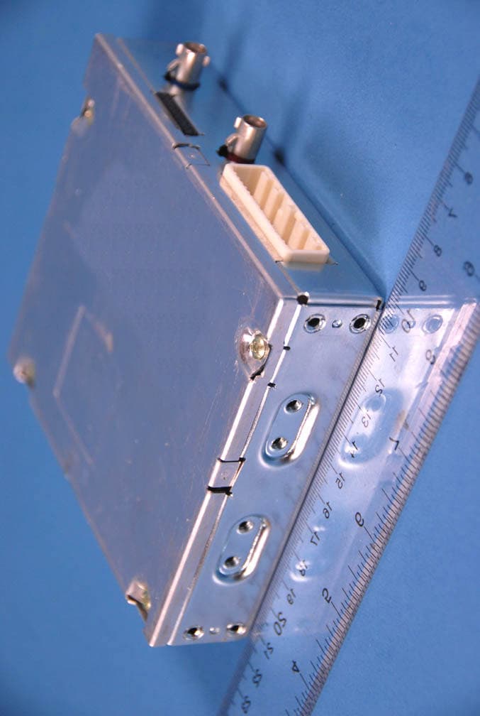
Click to zoom
Application Details
- Equipment Class
- PCB - PCS Licensed Transmitter
- Date of Grant
- May 27, 2010
- Application Purpose
- Original Equipment
- Date of Application
- May 27, 2010
- Equipment Note
- Cellular/PCS CDMA Automotive Transceiver Module
- Frequency Range
- 1851.25000000 - 1908.75000000
- Company
- LG Electronics USA, Inc.
- Country
- United States
Documents & Files
Document Text
Text extracted from the exhibit documents filed with the FCC. Open a document above to read the original.
Users Manual
User Manual For TMU (Preliminary) 1. Overview TMU(Telematics Unit, Model name: LT-10MCGVH) is pre-equipped on the vehicle factory to provide customer with various services such as Economic Driving Coach, Safety and Security, Roadside Assistance, etc. 2. Operation User can trigger various services TMU provides with by pressing one of 3 buttons on the Inside Mirror 2.1. SOS – Emergency Assistance In the event of an emergency ( e.g., medical, fire, police, or minor accident that doesn’t trigger an ACN call), the customer can press the SOS button in the vehicle that connects the vehicle occupant(s) to a Response Specialist who is able to determine the location of the vehicle and contact the nearest PSAP (Public Safety Answering Point) to provide Emergency Assistance quickly and efficiently. 2.2. PTT – Push To Talk User can trigger SR(Speech Recognition) operation by pressing PTT button in order to get serviced various function such as Economic Drive Coach, Turn by Turn Navigation and TMU information quarry. 2.2.1. SR Command – ‘Route Summary’ Show the route summary 2.2.2. SR Command – ‘Cancel Route’ Cancel the current route 2.2.3. SR Command – ‘Suspend Route’ Suspend the current route 2.2.4. SR Command – ‘Resume Route’ Resume the previously suspended route 2.2.5. SR Command – ‘Route Preview’ Preview the route for the desired destination 2.2.6. SR Command – ‘Save Destination’ Save the desired destination with the voice name tag. 2.2.7. SR Command – ‘Navigate To’ Choose the saved destination or start the navigation 2.2.8. SR Command – ‘Daily Route’ Start the navigation for the saved daily route 2.2.9. SR Command – ‘Destination List’ Show the list of saved destinations 2.2.10. SR Command – ‘Voice Guidance’ Turn on/off the voice guidance 2.2.11. SR Command – ‘Reroute’ Recalculate the route for the current destination 2.2.12. SR Command – ‘Setup’ Set various parameters of TMU such as distance unit, voice prompt, notifications 2.2.13. SR Command – ‘Help’ List entire SR command set. 2.3. IVR – Interactive Voice Recognition User can connect to service provider center by pressing IVR button in order to use various services. When the voice call is connected between user and service provider center by IVR button, user will be directed to automatic response system or to response specialist. 3. Modem Function 3.1. SMS TMU utilizes most of services by SMS transfer. When SOS or IVT button is pressed or vehicle related events occurs, TMU sends SMS to desired destination – service center or emergency center. 3.2. Voice Call TMU utilizes MT(Mobile Terminated) Call in general use case. When SOS or IVR button pressed, TMU sends SMS to desired destination then wait for the incoming call from the destination. TMU will receive incoming call automatically after SMS is sent. For the exceptional case, TMU utilizes MO(Mobile Oriented) Call in order to send DTMF when in emergency case the service center or emergency center is not responding for the SMS TMU sent. 3.3. Packet Data TMU utilizes TCP/IP connection with service center to transmit/receive packet data through network in the case where destination/route data needs to be downloaded. 3.4. DTMF TMU utilizes MO Call to send DTMF when in emergency case the service center or emergency center is not responding for the SMS TMU sent. 4. Test Setup for TMU <Fig. 1 TMU Top View> <Fig. 2 TMU Front View> 4.1. Connect main cable & Power connection. - Connect the <Fig. 2>- Main Connector & the <Fig. 3>- Main terminal - GND Line in the <Fig. 3>- Power & GND Line links ground pin in Power Supply. - B+14V Line in the <Fig. 3>- Power & GND Line links 14V-power. <Fig. 3 TMU Main Cable> 4.2. Connect GPS & CDMA Antenna. - CDMA & GPS Antenna in the <Fig. 4> are connected to CDMA & GPS Antenna connector in the <Fig. 2> <Fig. 4 Antenna> “In order to comply with FCC RFx requirements, the EUT must be installed such that there is a minimum separation distance of 20 cm between the antenna and all persons during normal operation. The maximum cellular gain cannot exceed 9.72 dBi and the PCS antenna gain cannot exceed 7.73 dBi.” 4.3. LG Test Tool Setting. - Check the switch setting in LG test tool: Reference <Fig. 5-2> <Fig. 5-1 LG TMU Test Tool> <Fig. 5-2 Initial Switch Setting> - CAIT port in the LG TMU Test tool should be connected to PC with USB cable as <Fig. 6> <Fig. 6 USB Cable> - 20Pin Terminal in the <Fig. 7> is connected to 20Pin Connector in the <Fig. 5-1>. <Fig. 7 LG TMU Test Tool Cable> 4.4. Connection TMU & LG TMU Test Tool. - Debug Terminal in the <Fig. 7> is connected to Debug connector in the <Fig. 2> # Caution : White Point in Debug terminal matches Pin #1 in the <Fig 2.> <
Cover Letter(s)
APPLICANT : LG Electronics Inc. FCC ID : BEJLTTMU10, Canada IC : 2703C-LTTMU10 CONFIDETIALITY REQUEST CONTAINED WITHIN Federal Communications Commission Authorization and Evaluation Division 7435 Oakland Mills Road Columbia, Maryland 21046 Application: LG Electronics Inc., 221, Yangjae-Dong, Seocho-Gu, Seoul 137-130, Korea herein submits: Application for Equipment Authorization for certification of a Cellular Transceiver FCC ID:BEJLTTMU10. LGE is also the manufacturer of this equipment. This equipment is a subscriber unit installed in a vehicle. Confidentiality In accordance with 0.459 of CFR 47, LG Electronics, Inc. hereby requests confidentiality of the Block Diagrams, Schematic Diagram, Circuit Description, Operational Description and Part List/Tune-Up Procedure for the above referenced type acceptance application. These materials contains LGE’s secrets and confidential information that LGE does not customarily release to the public and which is otherwise not generally available to the public. Since this design is a basis from which future technological products will evolve, LG Electronics Inc. considers this information to be benefit to its competitors an unfair advantage in the market. Contact Information: Please contact me by e-mail [email protected], or by telephone 82-11-1749-3989, if there are questions or additional information needed concerning this filing. Regards, Kwang Jae Lee Engineering Director ------------------------ LG Electronics Inc. Digital Media Research Lab. 221, Yangjae-Dong, Seocho-Gu, Seoul 137-130, Korea
Cover Letter(s)
From: 한상진 Sent: Friday, May 28, 2010 12:46 PM To: Mark Czumak Subject: Re : RE: Follow-up Questions Regarding FCC ID: BEJLTTMU10 _ 5-27-10 Dear Mr. Mark Czumak, Thanks for your response, and I added the below comment to the user manual in 5 page. “In order to comply with FCC RFx requirements, the EUT must be installed such that there is a minimum separation distance of 20 cm between the antenna and all persons during normal operation. The maximum cellular gain cannot exceed 9.72 dBi and the PCS antenna gain cannot exceed 7.73 dBi.” Please refer to the attached file. Thank you. Best regards, Sangjin Han -- -- -- ---- Original Message ---------- From : "Mark Czumak" To : 한상진 선임연구원, 'PCTEST TCB/CB' Date : 10/5/28 6:56:27 Subj ect : RE: Follow-up Questions Regarding FCC ID: BEJLTTMU10 _ 5-27-10 Dear Mr. Han, Thank you for your response. In order to enable us to complete our review of the application and issue the grant, please add the following statement to the Users Manual and return: “In order to comply with FCC RFx requirements, the EUT must be installed such that there is a minimum separation distance of 20 cm between the antenna and all persons during normal operation. The maximum cellular gain cannot exceed 9.72 dBi and the PCS antenna gain cannot exceed 7.73 dBi.” Thank you, Mark Czumak PCTEST Certification Engineer From: Sangjin Han Sent: Thursday, May 27, 2010 5:01 PM To: 'PCTEST TCB/CB'; 'Mark Czumak' Subject: RE: Follow-up Questions Regarding FCC ID: BEJLTTMU10 _ 5- 27-10 Dear Mr. Mark Czumak, Thanks for your kind response, and I’d like to send the revised document. I revised the Tune-up procedure_v1.0.doc and Operational Description LT-10MCGVH_v1.0.doc., which contained the comment “The conducted powers are Cellular: 24.76 dBm and PCS: 25.27 dBm. Per the MPE Test Report the maximum Cellular gain cannot exceed 9.72 dBi and the PCS antenna gain cannot exceed 7.73 dBi.” Please refer to the attached file. And, would you please let me know the FCC grant until 5/28 (original target date)? Thank you. Best regards, Sangjin Han From: PCTEST TCB/CB Sent: Friday, May 28, 2010 2:14 AM To: '한상진' Subject: RE: Follow-up Questions Regarding FCC ID: BEJLTTMU10 _ 5 -27-10 Dear Mr. Han, Thank you for your email. Follow-up questions below: 1. The conducted powers are Cellular: 24.76 dBm, PCS: 25.27 dBm. Per the MPE Test Report the maximum Cellular gain cannot exceed 9.72 dBi and the PCS antenna gain cannot exceed 7.73 dBi. Please revise the document to include the actual test result numbers. The item indicated above must be submitted before processing can continue on the above referenced application. Sincerely, PCTEST TCB From: 한상진 Sent: Wednesday, May 26, 2010 3:39 PM To: PCTEST TCB/CB Subject: Re : F ollow-up Questions Regarding FCC ID: BEJLTTMU10 (MODIFIED) Dear Mr. Mark Czumak, Thanks for your comment, and I’d like to reply for you comments. 1. The maximum antenna gains listed under the RF Exposure section in the FCC Information document do not match what is provided in the MPE test report. Use of maximum gains listed in the manual could yield potentially non-compliant results. Please revise the document to include the actual test result numbers. → In fact, I don't know what is the measurement value in the MPE test report. Would you please let me know maximum conducted power both DCN and PCS? 2. Pursuant to Part 15.103 of CFR Title 47, digital devices are exempt from Part 15 authorization requirements. Therefore, please remove the 15.19 and 15.21 statements from the FCC Information document so that they will not be placed in the users manual. → I am sorry, and I removed 15.19 and 15.21 statements comment. Please refer to the attached file. Your prompt response will be highly appreciated. Thank you. Best regards, Sangjin Han ---------- Original Message ---------- From : "PCTEST TCB/CB" To : 한상진 선임연구원 Date : 10/5/27 2:59:45 Subject : Follow-up Questions Regarding FCC ID: BEJLTTMU10 (MODIFIED) Dear Mr. Han, Thank you for your email. Follow-up questions below: 1. The maximum antenna gains listed under the RF Exposure section in the FCC Information document do not match what is provided in the MPE test report. Use of maximum gains listed in the manual could yield potentially non-compliant results. Please revise the document to include the actual test result numbers. 2. Pursuant to Part 15.103 of CFR Title 47, digital devices are exempt from Part 15 authorization requirements. Therefore, please remove the 15.19 and 15.21 statements from the FCC Information document so that they will not be placed in the users manual. The item indicated above must be submitted before processing can continue on the above referenced application. Sincerely, Mark Czumak Certification Engineer From: Sangjin Han Sent: Monday, May 24, 2010 9:24 PM To: 'PCTEST TCB/CB'; 'PCTEST - Gregory Czumak' Subject: RE: Questions Regard ing FCC ID: BEJLTTMU10 Dear Mr. Mark Czumak, Thank you for your information, and I’d like to reply for you comments. 1. The QSC6055 portion of the block diagram has three unlabeled oscillators. Please resubmit listing the values of all clocks and oscillators. → I have updated block diagram with listing of thress oscillators There are 32.768kHz sleep crystal and 19.2MHz TCXO in QSC6055. And GSC3e Sirf IC have one 32.768kHz RTC. 2. The Tune-up procedure does not include conducted power target ranges. Please revise to include the maximum powers and tolerances per band. → Conducted maximum power : Under 25dBm both DCN and PCS band. I have added this comment 3. The X201 crystal oscillator on page 2 of the schematic diagrams does not have a frequency listed. Please revise to include the oscillator frequency. → I have updated X201 (32.768kHz) crystal in block diagram and schematics 4. The X402 crystal oscillator on page 4 of the schematic diagrams does not have a frequency listed. Please revise to include the oscillator frequency. → I have updated X402 (32.768kHz) crystal in block diagram and schematics 5. The ins…
Text truncated - open the document above for the full version.
External Photos
LG FCC ID: BEJLTTMU10 Model: LT-10MCGVH External Photos EUT Type: Cellular/PCS CDMA Tranceiver Page 1 of 4 © 2010 PCTEST Engineering Laboratory Inc. EXTERNAL PHOTOGRAPHS LG FCC ID: BEJLTTMU10 Model: LT-10MCGVH External Photos EUT Type: Cellular/PCS CDMA Tranceiver Page 2 of 4 © 2010 PCTEST Engineering Laboratory Inc. LG FCC ID: BEJLTTMU10 Model: LT-10MCGVH External Photos EUT Type: Cellular/PCS CDMA Tranceiver Page 3 of 4 © 2010 PCTEST Engineering Laboratory Inc. LG FCC ID: BEJLTTMU10 Model: LT-10MCGVH External Photos EUT Type: Cellular/PCS CDMA Tranceiver Page 4 of 4 © 2010 PCTEST Engineering Laboratory Inc.
ID Label/Location Info
FCC ID : BEJLTTMU10VER : Rev.DMEID : A0000003F93284Made in Korea LG Electronics Inc. LG Label Location
Internal Photos
LG FCC ID: BEJLTTMU10 Model: LT-10MCGVH Internal Photos EUT Type: Cellular/PCS CDMA Tranceiver Page 1 of 8 © 2010 PCTEST Engineering Laboratory Inc. INTERNAL PHOTOGRAPHS LG FCC ID: BEJLTTMU10 Model: LT-10MCGVH Internal Photos EUT Type: Cellular/PCS CDMA Tranceiver Page 2 of 8 © 2010 PCTEST Engineering Laboratory Inc. LG FCC ID: BEJLTTMU10 Model: LT-10MCGVH Internal Photos EUT Type: Cellular/PCS CDMA Tranceiver Page 3 of 8 © 2010 PCTEST Engineering Laboratory Inc. LG FCC ID: BEJLTTMU10 Model: LT-10MCGVH Internal Photos EUT Type: Cellular/PCS CDMA Tranceiver Page 4 of 8 © 2010 PCTEST Engineering Laboratory Inc. LG FCC ID: BEJLTTMU10 Model: LT-10MCGVH Internal Photos EUT Type: Cellular/PCS CDMA Tranceiver Page 5 of 8 © 2010 PCTEST Engineering Laboratory Inc. LG FCC ID: BEJLTTMU10 Model: LT-10MCGVH Internal Photos EUT Type: Cellular/PCS CDMA Tranceiver Page 6 of 8 © 2010 PCTEST Engineering Laboratory Inc. LG FCC ID: BEJLTTMU10 Model: LT-10MCGVH Internal Photos EUT Type: Cellular/PCS CDMA Tranceiver Page 7 of 8 © 2010 PCTEST Engineering Laboratory Inc. LG FCC ID: BEJLTTMU10 Model: LT-10MCGVH Internal Photos EUT Type: Cellular/PCS CDMA Tranceiver Page 8 of 8 © 2010 PCTEST Engineering Laboratory Inc.
Test Report
Reviewed by: FCC ID: BEJLTTMU10 FCC Pt. 22/24 CDMA MEASUREMENT REPORT (CERTIFICATION) Quality Manager Test Report S/N: Test Dates: EUT Type: 0Y1005070773.BEJ May 13, 2010 Cellular/PCS CDMA Transceiver Page 1 of 36 © 2010 PCTEST Engineering Laboratory, Inc. REV 1.2CFI 04/19/2010 Applicant Name: Date of Testing: LG Electronics USA May 13, 2010 1000 Sylvan Avenue Test Site/Location: Englewood Cliffs, NJ 07632 PCTEST Lab., Columbia, MD, USA United States Test Report Serial No.: 0Y1005070773.BEJ FCC ID: BEJLTTMU10 APPLICANT: LG ELECTRONICS USA Application Type: Certification FCC Classification: PCS Licensed Transmitter (PCB) FCC Rule Part(s): §2; §22(H), §24(E) IC Specification(s): RSS-129 Issue 2; RSS-133 Issue 5 EUT Type: Cellular/PCS CDMA Transceiver Model(s): LT-10MCGVH Tx Frequency Range: 824.70 - 848.31MHz (Cell. CDMA) / 1851.25 - 1908.75MHz (PCS CDMA) Max. Conducted Power: 0.299 W Cell. CDMA (24.76 dBm) / 0.337 W PCS CDMA (25.27 dBm) Emission Designator(s): 1M27F9W (CDMA) / 1M28F9W (PCS) Test Device Serial No.: identical prototype [S/N: A100000C200012] This equipment has been shown to be capable of compliance with the applicable technical standards as indicated in the measurement report and was tested in accordance with the measurement procedures specified in §2.947. Test results reported herein relate only to the item(s) tested. I attest to the accuracy of data. All measurements reported herein were performed by me or were made under my supervision and are correct to the best of my knowledge and belief. I assume full responsibility for the completeness of these measurements and vouch for the qualifications of all persons taking them. Grant Conditions: Power output listed is conducted for Part 22 and 24.. PCTEST certifies that no party to this application has been denied the FCC benefits pursuant to Section 5301 of the Anti-Drug Abuse Act of 1988, 21 U.S.C. 862. PCTEST ENGINEERING LABORATORY, INC. 6660-B Dobbin Road, Columbia, MD 21045 USA Tel. 410.290.6652 / Fax 410.290.6554 http://www.pctestlab.com MEASUREMENT REPORT FCC Part 22 & 24 / IC RSS-129/RSS-133 Reviewed by: FCC ID: BEJLTTMU10 FCC Pt. 22/24 CDMA MEASUREMENT REPORT (CERTIFICATION) Quality Manager Test Report S/N: Test Dates: EUT Type: 0Y1005070773.BEJ May 13, 2010 Cellular/PCS CDMA Transceiver Page 2 of 36 © 2010 PCTEST Engineering Laboratory, Inc. REV 1.2CFI 04/19/2010 TABLE OF CONTENTS FCC PART 22 & 24 MEASUREMENT REPORT...........................................................................3 1.0 INTRODUCTION....................................................................................................................4 1.1 SCOPE..................................................................................................................................................................4 1.2 TESTING FACILITY............................................................................................................................................4 2.0 PRODUCT INFORMATION.....................................................................................................5 2.1 EQUIPMENT DESCRIPTION...........................................................................................................................5 2.2 EMI SUPPRESSION DEVICE(S)/MODIFICATIONS....................................................................................5 2.3 LABELING REQUIREMENTS...........................................................................................................................5 3.0 DESCRIPTION OF TESTS......................................................................................................6 3.1 MEASUREMENT PROCEDURE......................................................................................................................6 3.2 OCCUPIED BANDWIDTH.................................................................................................................................6 3.3 CELLULAR - BASE FREQUENCY BLOCKS.................................................................................................6 3.4 CELLULAR - MOBILE FREQUENCY BLOCKS.............................................................................................7 3.5 PCS - BASE FREQUENCY BLOCKS..............................................................................................................7 3.6 PCS - MOBILE FREQUENCY BLOCKS.........................................................................................................7 3.7 SPURIOUS AND HARMONIC EMISSIONS AT ANTENNA TERMINAL...................................................7 3.8 RADIATED POWER AND RADIATED SPURIOUS EMISSIONS...............................................................8 3.9 PEAK-AVERAGE RATIO...................................................................................................................................8 3.10 FREQUENCY STABILITY / TEMPERATURE VARIATION.........................................................................8 4.0 TEST EQUIPMENT CALIBRATION DATA...............................................................................9 5.0 SAMPLE CALCULATIONS....................................................................................................10 6.0 TEST RESULTS...................................................................................................................11 6.1 SUMMARY.........................................................................................................................................................11 6.2 TRANSMITTER CONDUCTED OUTPUT POWER.....................................................................................12 6.3 CELLULAR CDMA RADIATED MEASUREMENTS....................................................................................13 6.4 PCS CDMA RADIATED MEASUREMENTS................................................................................................16 6.5 CELLULAR CDMA FREQUENCY STABILITY MEASUREMENTS................…
Text truncated - open the document above for the full version.
Test Report
Reviewed by: FCC ID: BEJLTTMU10 MAXIMUM PERMISSIBLE EXPOSURE (MPE) DATA REPORT Quality Manager Test Report S/N: Test Dates: EUT Type: 0Y1005200849.BEJ May 20, 2010 Cellular/PCS CDMA Transceiver Page 1 of 7 © 2010 PCTEST Engineering Laboratory, Inc. REV 3.1MPE 02/09/09 Applicant Name: Date of Testing: LG Electronics USA May 20, 2010 18600 Broadwick St. Test Site/Location: Rancho Dominguez, CA 90220 PCTEST Lab, Columbia, MD, USA United States Test Report Serial No.: 0Y1005200849.BEJ FCC ID: BEJLTTMU10 APPLICANT: LG Electronics USA EUT Type: Cellular/PCS CDMA Transceiver FCC Rule Part(s): FCC Part 1 (§1.1310) and Part 2 (§2.1091) FCC Classification: PCS Licensed Transmitter (PCB) Test Procedure: OET Bulletin 65 The device bearing the FCC Identifier specified above has been shown to comply with the applicable technical standards as indicated in the measurement report and has been tested in accordance with the measurement procedures specified in FCC OET Bulletin 65 (See Test Report). These measurements were performed with no deviation from the standards. Test results reported herein relate only to the item(s) tested. I authorize and attest to the accuracy of data. All measurements reported herein were performed by me or were made under my supervision and are correct to the best of my knowledge and belief. I assume full responsibility for the completeness of these measurements and vouch for the qualifications of all persons taking them. PCTEST certifies that no party to this application has been denied the FCC benefits pursuant to Section 5301 of the Anti-Drug Abuse Act of 1988, 21 U.S.C. 862. PCTEST ENGINEERING LABORATORY, INC. 6660-B Dobbin Road, Columbia, MD 21045 USA Tel. 410.290.6652 / Fax 410.290.6554 http://www.pctestlab.com RF EXPOSURE EVALUATION (MAXIMUM PERMISSIBLE EXPOSURE) Reviewed by: FCC ID: BEJLTTMU10 MAXIMUM PERMISSIBLE EXPOSURE (MPE) DATA REPORT Quality Manager Test Report S/N: Test Dates: EUT Type: 0Y1005200849.BEJ May 20, 2010 Cellular/PCS CDMA Transceiver Page 2 of 7 © 2010 PCTEST Engineering Laboratory, Inc. REV 3.1MPE 02/09/09 TABLE OF CONTENTS 1.0 RF EXPOSURE EVALUATION – MAXIMUM PERMISSIBLE EXPOSURE (MPE).......................3 1.1 INTRODUCTION...................................................................................................................................................3 1.2 EUT DESCRIPTION.............................................................................................................................................3 1.3 MPE REQUIREMENTS OVERVIEW.................................................................................................................4 1.4 PROCEDURE........................................................................................................................................................5 1.5 SUMMARY OF RESULTS...................................................................................................................................6 2.0 CONCLUSION.......................................................................................................................7 Reviewed by: FCC ID: BEJLTTMU10 MAXIMUM PERMISSIBLE EXPOSURE (MPE) DATA REPORT Quality Manager Test Report S/N: Test Dates: EUT Type: 0Y1005200849.BEJ May 20, 2010 Cellular/PCS CDMA Transceiver Page 3 of 7 © 2010 PCTEST Engineering Laboratory, Inc. REV 3.1MPE 02/09/09 1.0 RF EXPOSURE EVALUATION – MAXIMUM PERMISSIBLE EXPOSURE (MPE) 1.1 Introduction This document is prepared on behalf of LG Electronics USA to show compliance with the RF Exposure requirements as required in §1.1310 of the FCC Rules and Regulations and RSS-102 of Industry Canada. The limit for Maximum Permissible Exposure (MPE), specified in FCC §1.1310, is listed in Table 1-1. According to FCC §1.1310 and RSS-102: the criteria listed in the following table shall be used to evaluate the environmental impact of human exposure to radio-frequency (RF) radiation as specified in §1.1307(b). Frequency Range (MHz) Electric Field Strength (V/m) Magnetic Field Strength (A/m) Power Density (mW/cm 2 ) Average Time (Minutes) (A) Limits For Occupational / Control Exposures (f = frequency) 30-300 61.4 0.163 1.0 6 300-1500 ... ... f/300 6 1500-100,000 ... ... 5.0 6 (B) Limits For General Population / Uncontrolled Exposure (f = frequency) 30-300 27.5 0.073 0.2 30 300-1500 ... ... f/1500 30 1500-100,000 ... ... 1.0 30 Table 1-1. Limits for Maximum Permissible Exposure (MPE) 1.2 EUT Description The LG Model: LT-10MCGVH is a Cellular/PCS CDMA Transceiver. For this MPE evaluation the maximum permissible antenna gain is calculated based on the power density limit in the Cellular band, and the EIRP limit in the PCS band as limiting factors. EUT: Model: LT-10MCGVH Grantee: LG Electronics USA FCC ID: BEJLTTMU10 Conducted Powers: 24.76 dBm (Cellular CDMA) 25.27 dBm (PCS CDMA) Reviewed by: FCC ID: BEJLTTMU10 MAXIMUM PERMISSIBLE EXPOSURE (MPE) DATA REPORT Quality Manager Test Report S/N: Test Dates: EUT Type: 0Y1005200849.BEJ May 20, 2010 Cellular/PCS CDMA Transceiver Page 4 of 7 © 2010 PCTEST Engineering Laboratory, Inc. REV 3.1MPE 02/09/09 1.3 MPE Requirements Overview Three different categories of transmitters are defined by the FCC in OET Bulletin 65. These categories are fixed installation, mobile, and portable and are defined as follows: o Fixed Installations: fixed location means that the device, including its antenna, is physically secured at a permanent location and is not able to be easily moved to another location. Additionally, distance to humans from the antenna is maintained to at least 2 meters. o Mobile Devices: a mobile device is defined as a transmitting device designed to be used in other than fixed locations and to be generally used in such a way that a separation distance of at least 20 centimeters is normally maintained between the transmitter's radiating structures and the body of the user or nearby persons. Transmitters designed to be used by consumers or workers that can be …
Text truncated - open the document above for the full version.
Test Setup Photos
LG FCC ID: BEJLTTMU10 Model: LT-10MCGVH Test Set-Up Photos EUT Type: Cellular/PCS CDMA Tranceiver Page 1 of 2 © 2010 PCTEST Engineering Laboratory Inc. TEST SETUP PHOTOGRAPHS LG FCC ID: BEJLTTMU10 Model: LT-10MCGVH Test Set-Up Photos EUT Type: Cellular/PCS CDMA Tranceiver Page 2 of 2 © 2010 PCTEST Engineering Laboratory Inc.
Contact Information
Applicant
David Kim(Team leader, LGEUS NA Policy & Regulatory Affairs)
Technical Contact
PCTEST Engineering Laboratory, Inc.Randy Ortanez
[email protected]410-290-6652
6660-B Dobbin Road · Columbia, Maryland · United States
Test Firm
PCTEST Engineering Laboratory, Inc.Randy Ortanez
Technical Specifications
| # | Rule Parts | Frequency Range | Power Output | Emission | Tolerance |
|---|---|---|---|---|---|
| 2 | 24E | 1.85 GHz - 1.91 GHz | 337.00 mW | 1M28F9W | 2.5 ppm |
Other Applications from LG Electronics USA, Inc.

BEJTFHOBINI1F1
Jan 08, 2025Telematics
Equipment Class
DTS - Digital Transmission SystemBEJNT-16Z90TS
Oct 02, 2024Notebook Computer
Equipment Class
DSS - Part 15 Spread Spectrum TransmitterBEJSP-PEW8
Sep 26, 2024Stylus Pen
Equipment Class
DCD - Part 15 Low Power Transmitter Below 1705 kHzBEJ-RSMV2
Sep 24, 2024RF Module
Equipment Class
FDS - Part 15 Field Disturbance SensorBEJTFBMEIBN3EU
Sep 24, 2024Telematics
Equipment Class
NII - Unlicensed National Information Infrastructure TX