BEJLW2100APWireless LAN
LG Electronics USA, Inc.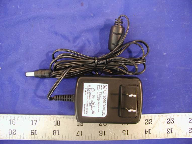
Click to zoom
Application Details
- Equipment Class
- DSS - Part 15 Spread Spectrum Transmitter
- Date of Grant
- Jul 17, 2002
- Application Purpose
- Original Equipment
- Date of Application
- Jul 17, 2002
- Equipment Note
- Wireless LAN
- Frequency Range
- 2412.00000000 - 2462.00000000
- Company
- LG Electronics USA, Inc.
- Country
- United States
Documents & Files
Document Text
Text extracted from the exhibit documents filed with the FCC. Open a document above to read the original.
Users Manual
LW2100AP User’s Manual Version 1.4 2002.05.14 Copyright© 2002 LG Electronics Inc., LTD. Page 1 of 46 L L W W 2 2 1 1 0 0 0 0 A A P P U U s s e e r r ’ ’ s s M M a a n n u u a a l l LW2100AP User’s Manual Version 1.4 2002.05.14 Copyright© 2002 LG Electronics Inc., LTD. Page 2 of 46 Chapter 1 Overview of the system.......................................................................................... 4 1.1 Introduction......................................................................................................................... 4 1.1.1. Specification ............................................................................................................................... 5 1.1.2. Appearance.................................................................................................................................. 6 1.1.3. Components ................................................................................................................................ 8 1.2. Hardware Installation............................................................................................... 9 1.3. Network Setting for PC..........................................................................................11 Chapter 2 WEB Server Manual........................................................................................ 14 2.1 Execution of WEB Server and AP connection to WEB Server ............................................................................................................................................... 14 2.2. Menu description of WEB Server............................................................... 16 2.2.1. Basic configuration Menu ......................................................................................................... 16 2.2.2. 802.11b Menu ........................................................................................................................... 20 2.2.3. RADIUS Server Menu .............................................................................................................. 23 2.2.4. DHCP/NAT Server Menu ...................................................................................................... 25 2.2.5. SNMP Server Menu ............................................................................................................... 27 2.2.6. DMZ Server Menu................................................................................................................. 29 2.2.7. MAC Filter Menu ..................................................................................................................... 30 2.2.8. IP Filter Menu ........................................................................................................................... 32 2.2.9 Advanced Menu ...................................................................................................................... 34 2.2.10. Save Menu .............................................................................................................................. 36 2.2.11. Reboot Menu........................................................................................................................... 37 2.2.12. Upgrade Menu ........................................................................................................................ 38 2.2.13. Default Value Menu ................................................................................................................ 39 Chapter 3 Console Window Manual.................................................................................. 40 3.1. Connecting Console Window......................................................................... 40 3.2. Setting Configuration Elements.................................................................. 43 LW2100AP User’s Manual Version 1.4 2002.05.14 Copyright© 2002 LG Electronics Inc., LTD. Page 3 of 46 All the contents described in the document may not be used without written permission of LG Electronics Inc., Ltd. This user manual may be changed without notification as function and specification of LW2100AP have changed, and the changed contents can be free downloaded when you visit our The intellectual rights of this user manual belong to LG Electronics Inc., Ltd. Microsoft, Windows, Windows95, Windows98, Windows ME, Windows 2000 and Windows NT are trademarks of Microsoft Corporation. Other company names or products stated in this user manual may be trademarks of each company or owner. LW2100AP User’s Manual Version 1.4 2002.05.14 Copyright© 2002 LG Electronics Inc., LTD. Page 4 of 46 Chapter 1 Overview of the system 1.1 Introduction The LW2100AP delivers the freedom to configure the network without wire and functions as an IEEE 802.3 Ethernet-based Residential Gateway. It provides 10/100 Dual Speed Ethernet port for a DSL Modem, Cable Modem, or other Broadband access device and one 10M Ethernet port for connection to a home or small office network. LW2100AP can forward all packet between local and Internet such as ICMP, FTP, Real Audio, Quake, H.225 packet. Also support virtual server(DMZ server) that forward incoming packet to specified LAN host system. LW2100AP supports DHCP server to setup network configuration for each local PC dynamically. LW2100AP use graphical user interface(web-browser) to setup, check system status, change password, and upgrade system image. The LW2100AP has one local 10Mbps Ethernet port and one 10/100Mbps Dual Speed Ethernet global port. The local port can be connected directly to a single computer or it can be connected to an Ethernet hub or switch to provide Internet Sharing and Firewall protection to a local area network. The global port can be connected to any Cable, DSL, or Broadband modem with an Ethernet port. Unlike proxy server or NAT software that requires the software server to remain visible on the Internet, no local computers are directly and externally visible wh…
Text truncated - open the document above for the full version.
Cover Letter(s)
Federal Communication Commission Authorization and Evaluation Division Confidentiality Request regarding application for certification of FCC ID: BEJLW2100AP Pursuant to Sections 0.457 and 0.459 of the Commission’s Rules, we hereby request confidential treatment of information accompanying this application as outlined below: 1. Circuit Diagram 2. Block Diagram 3. Operational Description The above materials contain trade secrets and proprietary information not customarily released to the public. The public disclosure of these materials may be harmful to the applicant and provide unjustified benefits to its competitors. The application understands that pursuant to Section 0.457 of the Rules, disclosure of this application and all accompanying documentation will not be made before the date of the Grant for this application. Sincerely, Solomon Sim / Approval Part Leader Enterprise Communication Lab. System Company / LG Electronics Inc.
External Photos
EXHIBIT C - EUT EXTERNAL PHOTOGRAPHS Chassis - Front View Chassis - Rear View Chassis - Top View with Antenna Chassis - Bottom View with Antenna Chassis - Port View Power Adapter - Top View
ID Label/Location Info
EXHIBIT A - FCC ID LABELING AND WARNING STATEMENT FCC ID Label Proposed Label Location on EUT Bottom Side of EUT/Proposed Label Location FCC Warning Statement The device shall bear the following FCC statement. If the EUT is so small or for such use that it is not practicable to place the statement on it, the statement shall be placed in a prominent location in the instruction manual or pamphlet supplied to the user or, alternatively, shall be placed on the container in which the device is marketed. However, the FCC identifier or the unique identifier, as appropriate, must be displayed on the device. “This device complies with Part 15 of the FCC Rules. Operation is subject to the following two conditions: (1) this device may not cause harmful interference, and (2) this device must accept any interference received, including interference that may cause undesired operation.” FCC ID: BEJLW2100AP This device complies with Part 15 o the FCC Rules. Operation is subject to the following two conditions: (1) this device may not cause harmful interference, and (2) this device must accept any interference received, including interference that may cause undesired operation. Caution: To comply with FCC RF exposure requirements, a separation distance of at least 8 inches (20cm) must be maintained between the antenna of this and all persons. 1.0"
Internal Photos
EXHIBIT C - EUT INTERNAL PHOTOGRAPHS Main Board - Component View Main Board - Solder View Transmitter - Component View Transmitter - Solder View
Test Report
Note: This test report is specially limited to the above client company and product model only. It may not be duplicated without prior written consent of Bay Area Compliance Laboratory Corporation. This report must not be used by the client to claim product endorsement by NVLAP or any agency of the U.S. Government. FCC PART 15 SUBPART C EMI MEASUREMENT AND TEST REPORT For LG Electronics, Inc. LG Kangseo B/D, 36, Munlae-Dong, 6-Ga, Youngdungpo-Gu, Seoul, 150-096, Korea FCC ID: BEJLW2100AP July 16, 2002 This Report Concerns: Original Report Equipment Type: Wireless LAN Test Engineer: Jeff Lee Report No.: R0206171 Test Date: June 24, 2002 Reviewed By: Benjamin Jing Prepared By: Bay Area Compliance Laboratory Corporation 230 Commercial Street Sunnyvale, CA 94085 Tel: (408) 732-9162 Fax: (408) 732-9164 LG Electronics, Inc. FCC ID: BEJLW2100AP Report # R0206171Rpt Page 2 of 27 FCC Part 15.247 TABLE OF CONTENTS 1 - GENERAL INFORMATION..................................................................................................................................4 1.1 PRODUCT DESCRIPTION FOR EQUIPMENT UNDER TEST (EUT) ..............................................................................4 1.2 OBJECTIVE.............................................................................................................................................................4 1.3 RELATED SUBMITTAL(S)/GRANT(S).......................................................................................................................4 1.4 TEST METHODOLOGY............................................................................................................................................4 1.5 TEST FACILITY.......................................................................................................................................................5 1.6 TEST EQUIPMENT LIST...........................................................................................................................................5 1.7 PC SYSTEM CONFIGURATION LIST AND DETAILS..................................................................................................6 1.8 LOCAL SUPPORT EQUIPMENT LIST AND DETAILS...................................................................................................6 1.9 EXTERNAL I/O CABLE LIST AND DETAILS.............................................................................................................6 2 - SYSTEM TEST CONFIGURATION AND REQUIREMENT............................................................................7 2.1 DESCRIPTION OF TEST CONFIGURATION................................................................................................................7 2.2 BLOCK DIAGRAM...................................................................................................................................................7 2.2 EQUIPMENT MODIFICATION...................................................................................................................................7 2.3 CONFIGURATION OF TEST SYSTEM.........................................................................................................................7 2.4 TEST SETUP BLOCK DIAGRAM...............................................................................................................................7 3 - SUMMARY OF TEST RESULTS..........................................................................................................................8 4 - CONDUCTED OUTPUT POWER.........................................................................................................................9 4.1 STANDARD APPLICABLE........................................................................................................................................9 4.2 MEASUREMENT PROCEDURE..................................................................................................................................9 4.3 MEASUREMENT RESULT........................................................................................................................................9 4.4 TEST EQUIPMENT...................................................................................................................................................9 4.5 TEST RESULTS.......................................................................................................................................................9 4.6 PLOTS FOR EFFECTIVE RADIATED POWER TEST RESULT.......................................................................................9 5 - SPURIOUS EMISSION.........................................................................................................................................11 5.1 STANDARD APPLICABLE......................................................................................................................................11 5.2 MEASUREMENT PROCEDURE................................................................................................................................11 5.3 MEASUREMENT DATA..........................................................................................................................................11 5.4 TEST RESULT.......................................................................................................................................................11 6 - 6 DB BANDWIDTH OF EMISSIONS .................................................................................................................15 6.1 STANDARD APPLICABLE......................................................................................................................................15 6.2 MEASUREMENT PROCEDURE................................................................................................................................15 6.3 MEASUREMENT DATA............................................................................…
Text truncated - open the document above for the full version.
Test Setup Photos
EXHIBIT B - TEST SETUP PHOTOGRAPHS Conducted Emission - Front View Conducted Emission - Rear View Radiated Emission - Front View Radiated Emission - Rear View
Contact Information
Applicant
David Kim(Team leader, LGEUS NA Policy & Regulatory Affairs)
Test Firm
Bay Area Compliance LaboratoryJohn Chan
Technical Specifications
| # | Rule Parts | Frequency Range | Power Output |
|---|---|---|---|
| 1 | 15C | 2.41 GHz - 2.46 GHz | 51.00 mW |
Other Applications from LG Electronics USA, Inc.

BEJTFHOBINI1F1
Jan 08, 2025Telematics
Equipment Class
DTS - Digital Transmission SystemBEJNT-16Z90TS
Oct 02, 2024Notebook Computer
Equipment Class
DSS - Part 15 Spread Spectrum TransmitterBEJSP-PEW8
Sep 26, 2024Stylus Pen
Equipment Class
DCD - Part 15 Low Power Transmitter Below 1705 kHzBEJ-RSMV2
Sep 24, 2024RF Module
Equipment Class
FDS - Part 15 Field Disturbance SensorBEJTFBMEIBN3EU
Sep 24, 2024Telematics
Equipment Class
NII - Unlicensed National Information Infrastructure TX