BEJM4201CE42" LCD Monitor
LG Electronics USA, Inc.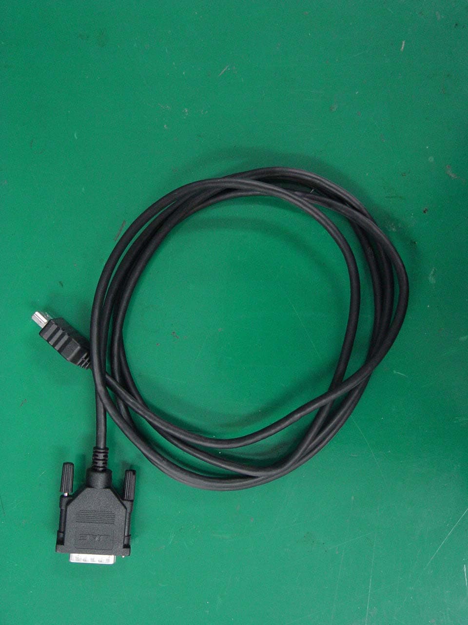
Click to zoom
Application Details
- Equipment Class
- JBP - Part 15 Class B Computing Device Peripheral
- Date of Grant
- Mar 27, 2006
- Application Purpose
- Original Equipment
- Date of Application
- Mar 27, 2006
- Equipment Note
- 42" LCD Monitor
- Company
- LG Electronics USA, Inc.
- Country
- United States
Documents & Files
Document Text
Text extracted from the exhibit documents filed with the FCC. Open a document above to read the original.
Users Manual
Test Report No.: GETEC-E3-06-014 FCC Class B Certification EUT Type: 42” LCD Monitor FCC ID: BEJM4201CE APPENDIX H : USER’S MANUAL A4 ENGLISH Accessories Speaker kit / Screws (Applicable only for models that support the speakers) Remote Control/ Batteries Power Cord Audio Cable (PC) Product OR Desktop Stand Type Free Mount Type Please check the accessories in the product package. * The product and the accessories can be different from the figures shown here. 15-pin D-Sub Signal Cable DVISignal Cable Wall-mount Rack (This has to be purchased separately if required.) Please refer to the enclosed "Installation Guide" when installing the wall-mount rack. User's Guide/ Driver CD/Cards 1. Take out the battery cap. 2. Insert batteries with correct polarity (+/-). 3. Close the battery cap. • You can use a remote Control 7 meter distance and 30 degree (left/right) within the receiving unit scope. • Dispose of used batteries in the recycle bin to prevent environmental pollution. Inserting batteries into remote Control. RCA-PC Audio Cable HDMI to DVI Signal Cable A5 Using the Remote Control Power On/Off Button •AV Button •Input Select Button (See next page) Sleep Button When watching AV/S-Video/ Component1/ Component2 - The product will be automatically turned off after a certain period of time. Press this button repetitively to select an appropriate time duration •Menu Button •Exit Button Auto Button •PC: Automatic adjustment function (Operational for the analog signal only) Check Button Video Operation Button Applicable for LG products only Volume Button Mute button Name of the Remote Control Buttons There is not a function which is supported PSM Button - Automatically adjusts the image. Press this button repetitively to set the intended screen. (See A23) •PC : Bring up and down direction adjustment. To select the image size of the screen. A6 ENGLISH If you press the button once, the following Input Signal Window will appear. Select the signal type you want using the button. •Input Select Button INPUT HDMI/DVI This button will be enabled only when you selected the AV signal. The signal type will be changed with the following order. Set the signal type you want. •AV Button AV HDMI/DVI RG B Component 2 Component1 A7 To arrange cables in order 1.Disassemble the stand cover.The cover may be easily disassembled by pressing down on the base as shown in the figure. 2.After connecting the cables, correctly position the stand cover into the holes on the stand. If securely connected, you will hear the latch click into place. Stand cover * Applicable only for models that support the stand A8 ENGLISH Connecting the Speakers Use the screws to secure the speakers on the rear side of the product as shown in the below figure. * Applicable only for models that support the speakers When the speaker is installed. A9 Name and Function of the Parts Rear View Power Connector : Connect the power cord Power connector and image are different by product size. Wired Remote Control Port RS-232C Serial Ports PC Signal Inputs PC Sound Jack : Connect the audio cable to the *LINE OUT jack of the PC sound card. AV Ports *LINE OUT A terminal used to connect to the speaker including a built-in amplifier (Amp). Make sure that the connecting terminal of the PC sound card is checked before connecting. If the Audio Out of PC sound card has only Speaker Out, reduce the PC volume. If the Audio Out of the PC sound card supports both Speaker Out and Line Out, convert to Line Out using the card jumper of the program (Refer to the Sound Card Manual). * The product image in the user’s guide could be different from the actual image. A10 ENGLISH First of all, see if the computer, product and the peripherals are turned off. Then, connect the signal input cable. When connecting with the D-Sub signal input cable. When connecting with the HDMI to DVI signal input cable. MAC Macintosh Adapter (not included) Use the standard Macintosh adapter since an incompatible adaptor is available in the market. (Different signaling system) Rear side of the product. * When connecting to a wall outlet. Connecting to External Devices Connect the power cord. B A B A PC When Connecting to your PC PC/MAC PC Rear side of the product. Rear side of the product. PC Rear side of the product. connect the Audio cable. A11 Select an input signal. Press the INPUT button on the remote control to select the input signal. Or, press the INPUT button at the front side of the product. INPUTSET •How to connect to two computers. Connect the signal cables ( HDMI to DVIand D-Sub) to each computer. Press the INPUT button in a remote control to select the computer to use. •Directly connect to a grounded power outlet on the wall or a power bar with a ground wire. Note Turn on power by pressing the power button on the product. Turn on the PC. Power button B A INPUT HDMI/DVI INPUT AUTO/SET When connecting with a D-Sub signal input cable. • Select RGB: 15-pin D-Subanalog signal. When connecting with a HDMI to DVI signal input cable. • Select HDMI/DVI:HDMI to DVIDigital signal. B A Connecting to External Devices A12 ENGLISH Use this function when displaying ANALOG RGB inputs of a PC to the other product. Product 1 •To use different products connected to each other Connect one end of the signal input cable(15-pin D-Sub Signal Cable) to the RGB OUT connector of product 1and connect the other end to the RGB INPUT connector of other products. Watching RGB Outputs PC Product 2 Product 3 Product 4 15-pin D-Sub Signal Cable A15 •SelectHDMI/DVI. Connect the video/audio cable as shown in the below figure and then connect the power cord (See page A11). RCA-PC Audio Cable Product VCR/DVD/Set-top Box HDMI to DVI Signal Cable INPUT HDMI/DVI When watchingHDMI/DVIfrom the VCR/DVD/Set-top Box VCR/DVD/Set-top Box Product Select an input signal. Press the INPUT button on the remote control to select the input signal. Or, press the INPUT button at the front side of the product. INPUTSET INPUT AUTO/SET HDMISigna…
Text truncated - open the document above for the full version.
Attestation Statements
Test Report No.: GETEC-E3-06-014 FCC Class B Certification EUT Type: 42” LCD Monitor APPENDIX A : ATTESTATION STATEMENT FCC ID: BEJM4201CE August 22, 2005 Federal Communications Commission Authorization and Evaluation Division Equipment Authorization Branch 7435 Oakland Mills Road Columbia, MD 21046 U.S.A To whom it may concern: We, the undersigned, hereby authorize GUMI College EMC Center to act on our behalf in all matters relating to applications for equipment authorization, including the signing of all documents relation to these matters. Any and all acts carried out by GUMI College EMC Center on our behalf shall have the same effect as acts of our own. We also hereby certify that no party to the application is subject of a denial of benefits, including FCC benefits, pursuant 5301 of the Anti-Drug Abuse Act of 1988, 21 U.S.C. 853(a). Sincerely, Woo-Hyun Oh, Group Leader LG Electronics Inc. TV Plant
Block Diagram
Test Report No.: GETEC-E3-06-014 FCC Class B Certification EUT Type: 42” LCD Monitor APPENDIX D : BLOCK DIAGRAM FCC ID: BEJM4201CE Chameleon Refresh Model Block Diagram ANX 9 02 1 (HDM I RX ' e r ) RX C ± / R X 0 ± RX 1 ± /RX 2 ± FL I86 6 2 ( C or t e z A d va n c e d ) NT P2 0 0 0 (Dig it al Aud io P ro ces s o r ) TAS 5 1 2 2 (D -C L A SS A M P ) NJ U 2 69 01 ( A udio De l a y ) LC F ILT E R OUT1A OUT1B OUT2A OUT2B M S P 4 44 0K (A ud io P ro ce ss o r ) AT49B V1 60 ( F la s h M e m ory) H Y 5D U 2 81 62 2 E T P (D DR S D R A M ) HY5D U 2 816 22 ET P (DDR SDR AM) CX A2 04 0AQ (Vid e o S wit c h ) LA 72 17 M (Vi d e o S y n c Se p e ra to r) 74 H C 1 4 D (S chm i tt T r i g g e r In v e r t er ) C M 20 21 (E SD Pr ot ec t o r ) IC L3 23 2C (R S23 2 C) AD8 009 ( O P A M P) PC R/G/B PC H/V SYNC PC R/G/B OUT PC H/V SYNC OUT PC H/V SYNC KEY CONT RO L B' D 32 " / 37 " / 4 2 " L C D P anel K E Y 1 / K E Y 2 PR EA M P I R WI R E C O N T R OL RX D / T X D RX C ± / R X 0 ± RX 1 ± /RX 2 ± 24 b it SYNC_DE V / Y_OUT C_OUT I2 S De l a y e d I 2 S Y/C CVB S CVB S O U T AV Audio IN Component Audio IN PC Audio IN AV Audio OUT Component 1,2 Y Pb Pr WI R E CONT R O L R S -232 C I N / O UT HD MI PC R GB IN / O U T C o m p o n e n t 1 , 2 I N PC A u d i o C o mpone n t 1 , 2 Au di o I N CVB S I N / O UT CVB S A u d i o I N / O UT S- V i d e o 27 MH z 1 9 .6608 MH z 1 8 .432M H z 500K H z
External Photos
Test Report No.: GETEC-E3-06-014 FCC Class B Certification EUT Type: 42” LCD Monitor APPENDIX F : EXTERNAL PHOTOGRAPHS FCC ID: BEJM4201CE Test Report No.: GETEC-E3-06-014 FCC Class B Certification EUT Type: 42” LCD Monitor FCC ID: BEJM4201CE Test Report No.: GETEC-E3-06-014 FCC Class B Certification EUT Type: 42” LCD Monitor FCC ID: BEJM4201CE Test Report No.: GETEC-E3-06-014 FCC Class B Certification EUT Type: 42” LCD Monitor FCC ID: BEJM4201CE Test Report No.: GETEC-E3-06-014 FCC Class B Certification EUT Type: 42” LCD Monitor FCC ID: BEJM4201CE
ID Label/Location Info
Test Report No.: GETEC-E3-06-014 FCC Class B Certification EUT Type: 42” LCD Monitor APPENDIX C : ID SAMPLE LABEL & LOCATION FCC ID: BEJM4201CE Test Report No.: GETEC-E3-06-014 FCC Class B Certification EUT Type: 42” LCD Monitor LABELLING REQUIREMENTS The label shown shall be permanently affixed at a conspicuous location on the device and be readily visible to the user at the time of purchase. ID Label ID Label Location of EUT I.D Label FCC ID: BEJM4201CE
Internal Photos
EUT Type: 42” LCD Monitor FCC ID: BEJM4201CE Test Report No.: GETEC-E3-06-014 FCC Class B Certification APPENDIX G : INTERNAL PHOTOGRAPHS EUT Type: 42” LCD Monitor FCC ID: BEJM4201CE Test Report No.: GETEC-E3-06-014 FCC Class B Certification EUT Type: 42” LCD Monitor FCC ID: BEJM4201CE Test Report No.: GETEC-E3-06-014 FCC Class B Certification EUT Type: 42” LCD Monitor FCC ID: BEJM4201CE Test Report No.: GETEC-E3-06-014 FCC Class B Certification EUT Type: 42” LCD Monitor FCC ID: BEJM4201CE Test Report No.: GETEC-E3-06-014 FCC Class B Certification EUT Type: 42” LCD Monitor FCC ID: BEJM4201CE Test Report No.: GETEC-E3-06-014 FCC Class B Certification EUT Type: 42” LCD Monitor FCC ID: BEJM4201CE Test Report No.: GETEC-E3-06-014 FCC Class B Certification EUT Type: 42” LCD Monitor FCC ID: BEJM4201CE Test Report No.: GETEC-E3-06-014 FCC Class B Certification EUT Type: 42” LCD Monitor FCC ID: BEJM4201CE Test Report No.: GETEC-E3-06-014 FCC Class B Certification EUT Type: 42” LCD Monitor FCC ID: BEJM4201CE Test Report No.: GETEC-E3-06-014 FCC Class B Certification EUT Type: 42” LCD Monitor FCC ID: BEJM4201CE Test Report No.: GETEC-E3-06-014 FCC Class B Certification EUT Type: 42” LCD Monitor FCC ID: BEJM4201CE Test Report No.: GETEC-E3-06-014 FCC Class B Certification EUT Type: 42” LCD Monitor FCC ID: BEJM4201CE Test Report No.: GETEC-E3-06-014 FCC Class B Certification EUT Type: 42” LCD Monitor FCC ID: BEJM4201CE Test Report No.: GETEC-E3-06-014 FCC Class B Certification EUT Type: 42” LCD Monitor FCC ID: BEJM4201CE Test Report No.: GETEC-E3-06-014 FCC Class B Certification EUT Type: 42” LCD Monitor FCC ID: BEJM4201CE Test Report No.: GETEC-E3-06-014 FCC Class B Certification EUT Type: 42” LCD Monitor FCC ID: BEJM4201CE Test Report No.: GETEC-E3-06-014 FCC Class B Certification EUT Type: 42” LCD Monitor FCC ID: BEJM4201CE Test Report No.: GETEC-E3-06-014 FCC Class B Certification EUT Type: 42” LCD Monitor FCC ID: BEJM4201CE Test Report No.: GETEC-E3-06-014 FCC Class B Certification
Test Report
Test Report No.: GETEC-E3-06-014 FCC Class B Certification EUT Type: 42” LCD Monitor APPENDIX B : PLOTS OF CONDUCTED EMISSIONS FCC ID: BEJM4201CE Test Report No.: GETEC-E3-06-014 FCC Class B Certification EUT Type: 42” LCD Monitor Test Mode: 1600*1200 / 60Hz(Analog) < Hot line > < Neutral line > FCC ID: BEJM4201CE Test Report No.: GETEC-E3-06-014 FCC Class B Certification EUT Type: 42” LCD Monitor Test Mode: 1280*1024 / 60Hz(Digital) < Hot line > < Neutral line > FCC ID: BEJM4201CE Test Report No.: GETEC-E3-06-014 FCC Class B Certification EUT Type: 42” LCD Monitor Test Mode:1024 *768 / 75Hz (Analog) < Hot line > < Neutral line > FCC ID: BEJM4201CE Test Report No.: GETEC-E3-06-014 FCC Class B Certification EUT Type: 42” LCD Monitor Test Mode: 640*480 / 60Hz (Analog) < Hot line > < Neutral line > FCC ID: BEJM4201CE
Test Report
Test Report No.: GETEC-E3-06-014 FCC Class B Certification EUT Type: 42” LCD Monitor CONTENTS 1. SCOPE...........................................................................................................................................................................3 2. INTRODUCTION........................................................................................................................................................4 3. TEST CONDITIONS & EUT INFORMATION........................................................................................................5 3.1 DESCRIPTION OF EUT..............................................................................................................................................5 3.2 SUPPORT EQUIPMENT USED.....................................................................................................................................6 4. DESCRIPTION OF TESTS.........................................................................................................................................7 4.1 CONDUCTED EMISSION............................................................................................................................................7 4.2 RADIATED EMISSION................................................................................................................................................8 5. CONDUCTED EMISSION..........................................................................................................................................9 5.1 OPERATING ENVIRONMENT.....................................................................................................................................9 5.2 TEST SET-UP..............................................................................................................................................................9 5.3 MEASUREMENT UNCERTAINTY................................................................................................................................9 5.4 LIMIT......................................................................................................................................................................10 5.5 TEST EQUIPMENT USED..........................................................................................................................................10 5.6 TEST DATA FOR POWER LINE CONDUCTED EMISSION............................................................................................11 6. RADIATED EMISSION............................................................................................................................................13 6.1 OPERATING ENVIRONMENT...................................................................................................................................13 6.2 TEST SET-UP............................................................................................................................................................13 6.3 MEASUREMENT UNCERTAINTY..............................................................................................................................13 6.4 LIMIT......................................................................................................................................................................14 6.5 TEST EQUIPMENT USED..........................................................................................................................................14 6.6 TEST DATA FOR RADIATED EMISSION.....................................................................................................................15 7. SAMPLE CALCULATIONS.....................................................................................................................................18 7.1 EXAMPLE 1 :...........................................................................................................................................................18 7.2 EXAMPLE 2 :...........................................................................................................................................................18 8. RECOMMENDATION & CONCLUSION..............................................................................................................19 APPENDIX A – ATTESTATION STATEMENT APPENDIX B – PLOTS OF CONDUCTED EMISSIONS APPENDIX C – ID SAMPLE LABEL & LOCATION APPENDIX D – BLOCK DIAGRAM APPENDIX E – TEST SET-UP PHOTOGRAPHS APPENDIX F – EXTERNAL PHOTOGRAPHS APPENDIX G –INTERNAL PHOTOGRAPHS APPENDIX H – USER’S MANUAL FCC ID: BEJM4201CE Page 2 of 19 Test Report No.: GETEC-E3-06-014 FCC Class B Certification EUT Type: 42” LCD Monitor 1. Scope Measurement and determination of electromagnetic emissions (EME) of radio frequency devices including intentional and / or unintentional radiators for compliance with technical rules and regulations of the Federal Communications Commission . Responsible Party: LG Electronics Inc. Contact Person: Mr. Woo-Hyun Oh, Chief research engineer Manufacturer: 642, Jinpyung-dong, Gumi-si, Gyeongsangbuk-do, Korea Tel No.: +82-54-470-5640 z FCC ID BEJM4201CE z EUT Type 42” LCD Monitor z Model No. M4201CE z Tra de Na me LG z Rule Part(s) FCC Part 15 Subpart B z Test Procedure(s) ANSI C63.4 (2003) / Canadian standard ICES-003 z Dates of Test February 28, 2006 z Place of Test Gumi College EMC Center z Test Report No. GETEC-E3-06-014 FCC ID: BEJM4201CE Page 3 of 19 Test Report No.: GETEC-E3-06-014 FCC Class B Certification EUT Type: 42” LCD Monitor 2. Introduction The measurement procedure described in American National Standard for Methods of Measurement of Radio-Nose Emissions From Low-Voltage Electrical and Electronic Equipment in the Range of 9kHz to 40GHz (ASNI C63.4- 2003) was used in determining radiated and conducted emissions emanating from LG Electronics Inc. 42” LCD Monitor(Model No.: M4201CE) These measurement tests were conducted at Gumi Colleg…
Text truncated - open the document above for the full version.
Test Setup Photos
Test Report No.: GETEC-E3-06-014 FCC Class B Certification EUT Type: 42” LCD Monitor APPENDIX E : TEST SET UP PHOTOGRAPHS FCC ID: BEJM4201CE Test Report No.: GETEC-E3-06-014 FCC Class B Certification EUT Type: 42” LCD Monitor Conducted Test Picture (Front) Conducted Test Picture (Rear) FCC ID: BEJM4201CE Test Report No.: GETEC-E3-06-014 FCC Class B Certification EUT Type: 42” LCD Monitor Radiated Test Picture (Front) Radiated Test Picture (Rear) FCC ID: BEJM4201CE
Contact Information
Applicant
David Kim(Team leader, LGEUS NA Policy & Regulatory Affairs)
Test Firm
GUMI UNIVERSITY EMC CENTERTea-Sig Park
Technical Specifications
| # | Rule Parts | Frequency Range | Power Output |
|---|---|---|---|
| 1 | 15B | - | - |
Other Applications from LG Electronics USA, Inc.

BEJTFHOBINI1F1
Jan 08, 2025Telematics
Equipment Class
DTS - Digital Transmission SystemBEJNT-16Z90TS
Oct 02, 2024Notebook Computer
Equipment Class
DSS - Part 15 Spread Spectrum TransmitterBEJSP-PEW8
Sep 26, 2024Stylus Pen
Equipment Class
DCD - Part 15 Low Power Transmitter Below 1705 kHzBEJ-RSMV2
Sep 24, 2024RF Module
Equipment Class
FDS - Part 15 Field Disturbance SensorBEJTFBMEIBN3EU
Sep 24, 2024Telematics
Equipment Class
NII - Unlicensed National Information Infrastructure TX