BEJN1710LTULED LCD MONITOR
LG Electronics USA, Inc.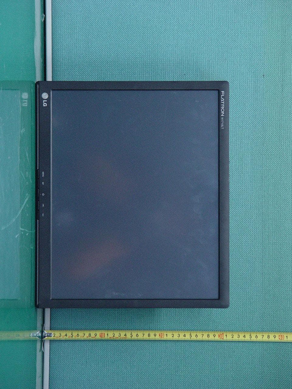
Click to zoom
Application Details
- Equipment Class
- JBP - Part 15 Class B Computing Device Peripheral
- Date of Grant
- Mar 17, 2011
- Application Purpose
- Original Equipment
- Date of Application
- Mar 17, 2011
- Equipment Note
- LED LCD MONITOR
- Company
- LG Electronics USA, Inc.
- Country
- United States
Documents & Files
Document Text
Text extracted from the exhibit documents filed with the FCC. Open a document above to read the original.
Users Manual
Order Number : GETEC-C1-11-045 FCC Part 15 subpart B Test Report Number : GETEC-E3-11-015 Page 1 / 1 EUT Type: LED LCD Monitor FCC ID.: BEJN1710LTU APPENDIX G : USER’S MANUAL www.lg.com OWNER’S MANUAL MULTI POS MONITOR L1710LT Please read this manual carefully before operating the your set and retain it for future reference. MULTI POS MODELS ENG ENGLISH 2 ENG ENGLISH TABLE OF CONTENTS CONTENTS 3 ASSEMBLING AND PREPARING 3 Unpacking 4 Parts and buttons 5 Setting up the Monitor set 5 - Mounting on a table 6 - Basic Adjustments of the Stand 7 - Detaching the Stand 8 - Mounting on a wall 9 USING THE MONITOR SET 9 Connecting to a RGB Cable 9 - Using the PC 9 - Using the MAC 10 To Use Touch Screen 10 - USB cable for the touch screen 11 CUSTOMIZING SETTINGS 11 Accessing main menus 12 Customizing settings 12 - SETUP settings 13 - COLOR settings 14 - TRACKING settings 15 - SETUP settings 16 - F·ENGINE settings 17 TROUBLESHOOTING 19 SPECIFICATIONS 3 ENG ENGLISH ASSEMBLING AND PREPARING ASSEMBLING AND PREPARING Unpacking Check your product box for the following items. If there are any missing accessories, contact the local dealer where you purchased your product. The illustrations in this manual may differ from the actual product and accessories. y Do not use any pirated items to ensure the safety and product life span. y Any damages or injuries by using pirated items are not covered by the warranty. y The accessories supplied with your product may vary depending on the model. y Product specifications or contents in this manual may be changed without prior notice due to upgrade of product functions. y User must use shielded signal interface cables (D-sub 15 pin cable) with ferrite cores to maintain standard compliance for the product. CAUTION NOTE Power Cord CD(Owner's Manual/ Software Installation) Easy Setup GuideCards Adaptor 4 ENG ENGLISH ASSEMBLING AND PREPARING y You can set the Power indicator to on or off by selecting OPTION in the main menus. NOTE Parts and buttons buttonDescription (Power Button) Turns the power on or off. AC-I NLANSERVICE Power Indicator y Lighting On: Turned on y Lighting Off: Turned off Connection panel ( See p.4) (Power Button) 5 ENG ENGLISH ASSEMBLING AND PREPARING Setting up the Monitor set Mounting on a table 1 Lift and tilt the Monitor set into its upright position on a table. Leave a 10 cm (minimum) space from the wall for proper ventilation. 2 Connect the Power Cord to a wall outlet. 3 Press button on the front switch panel to turn the power on. When monitor power is turned on, the 'Self Image Setting Function' is executed automatically. 10 cm 10 cm 10 cm 10 cm AC-IN Using the Kensington security system The Kensington security system connector is located at the back of the Monitor set. For more information of installation and using, refer to the manual supplied with the Kensington security system or visit http://www.kensington.com. Connect the Kensington security system cable between the Monitor set and a table. The Kensington security system is optional. You can obtain additional accessories from most electronics stores. NOTE 6 ENG ENGLISH ASSEMBLING AND PREPARING Basic Adjustments of the Stand 1 Adjust the angle of the panel as follows. y Tilt Range : 15° to 66° Do not push the stand with basic adjustment to the direction of the panel. The product may fall down to hurt people, or cause product disorder or screen damage. CAUTION y Push back the panel to the end, and use from the point that it automatically returns. 15° 66° Panel Stand 7 ENG ENGLISH ASSEMBLING AND PREPARING 2 After adjusting the angle of the panel for convenience, lock with the locking handle to. Prevent the product from moving when users touch the screen. y The state which the stand locking handle is released y The state which the stand locking handle is locked Detaching the Stand This Monitor set satisfies the specifications of the Wall mount plate or the interchange device. 1 Place the monitor with its front facing downward on a soft cloth. 2 Separate the head and the stand with the use of a screwdriver. 3 Remove 4 screws and pull out the Stand from the Monitor set. 8 ENG ENGLISH ASSEMBLING AND PREPARING y Disconnect the power cord first, and then move or install the Monitor set. Otherwise electric shock may occur. y If you install the Monitor set on a ceiling or slanted wall, it may fall and result in severe injury. Use an authorized LG wall mount and contact the local dealer or qualified personnel. y Do not over tighten the screws as this may cause damage to the Monitor set and void your warranty. y Use the screws and wall mounts that meet the VESA standard. Any damages or injuries by misuse or using an improper accessory are not covered by the warranty. y Use the screws that are listed on the VESA standard screw specifications. y The wall mount kit includes an installation manual and necessary parts. y The wall mount bracket is optional. You can obtain additional accessories from your local dealer. y The length of screws may differ depending on the wall mount. Be sure to use the proper length. y For more information, refer to the instructions supplied with the wall mount. CAUTION NOTE Model N1710LT VESA (A x B)75 x 75 Standard screwM4 Number of screws4 Wall mount bracket (optional) RW120 Mounting on a wall For proper ventilation, allow a clearance of 10 cm on each side and from the wall. Detailed installation instructions are available from your dealer, see the optional Tilt Wall Mounting Bracket Installation and Setup Guide. If you intend to mount the Monitor set to a wall, attach Wall mounting interface (optional parts) to the back of the set. When you install the Monitor set using the wall mounting interface (optional parts), attach it carefully so it will not drop. Please use VESA standard as below. y 784.8 mm (30.9 inch) and under * Wall Mount Pad Thickness : 2.6 mm * Screw : Φ 4.0 mm x Pitch 0.7 mm x Length 10 mm y 787.4 mm (31.0 inch) and above * Please use VESA standard wall mount …
Text truncated - open the document above for the full version.
Cover Letter(s)
SCS-F18: Project and Product Certification Representative Authorization Letter Page 1 of 2 Rev 2.0 2206 Ringwood Avenue San Jose, CA 95131 Tel: 408-526-1188 Fax: 408-526-1088 Email: [email protected] Project and Product Certification Representative Authorization Letter Revision History Reason for Amendment (current / obsolete) From To Approved Date Initial Release (current) 1.0 1.0 Nov-14-2006 Revised wording (current) 1.0 2.0 Sept–25-2007 SCS-F18: Project and Product Certification Representative Authorization Letter Page 2 of 2 Rev 2.0 March 18, 2011 To: SIEMIC, INC. 2206 Ringwood Avenue, San Jose, CA 95131 USA Dear Sir/Madam, Re: Project and Product Certification Representative Authorization Letter We, LG Electronics Inc., hereby authorize SIEMIC, INC. to act as a Certification Body for certifying for the following project(s): Product Name: LED LCD Monitor FCC ID: BEJN1710LTU We affirm that between SIEMIC and LG Electronics Inc., any difference in understanding, including test plan, measurement methods, applicable standards and relevant procedures and processes have been resolved prior to commencement of testing activities. Sincerely, Christopher Johnson, Sr. Manager LG Electronics USA LG Electronics USA 1000 Sylvan Avenue, En glewood Cliffs, NJ 07632, USA
Cover Letter(s)
Confidentiality Request Letter Revision History Reason for Amendment (current / obsolete) From To Approved Date Initial Release (current) 1.0 1.0 Nov-14-2006 SCS-F19: Confidentiality Request Letter Rev 1.0 Nov 14, 2006 Federal Communications Commission Authorization and Evaluation Division March 18, 2011 Confidentiality Request regarding application for certification of FCC ID: BEJN1710LTU We hereby request confidential treatment of information accompanying this application as outlined below: Exhibit Type File Name BLOCK DIAGRAM N1710LTU_BlkDia.pdf The above materials contain trade secrets and proprietary information not customarily released to the public. The public disclosure of these materials may be harmful to the applicant and provide unjustified benefits to its competitors. In addition to above mentioned documents, pursuant to Public DA 04-1705 of the Commission’s policy, in order to comply with the marketing regulations in 47 CFR 2.803 and the importation rules in 47 CFR 2.1204, while ensuring that business sensitive information remains confidential until the actual marketing of newly authorized devices. We are requesting the commission to grant short-term confidentiality request on the following Exhibit Type File Name TEST SET UP PHOTOGRAPHS N1710LTU_Tsup.pdf EXTERNAL PHOTOGRAPHS N1710LTU_ExtPho.pdf INTERNAL PHOTOGRAPHS N1710LTU_IntPho.pdf USER’S MANUAL N1710LTU_UseMan.pdf The applicant understands that pursuant to Section 0.457 of the Rules, disclosure of this application and all accompanying documentation will not be made before the date of the Grant for this application. Sincerely, Christopher Johnson, Sr. Manager LG Electronics USA LG Electronics USA 1000 Sylvan Avenue, En glewood Cliffs, NJ 07632, USA
External Photos
Order Number : GETEC-C1-11-045 FCC Part 15 subpart B Test Report Number : GETEC-E3-11-015 Page 1 / 8 EUT Type: LED LCD Monitor FCC ID.: BEJN1710LTU APPENDIX E : EXTERNAL PHOTOGRAPHS Order Number : GETEC-C1-11-045 FCC Part 15 subpart B Test Report Number : GETEC-E3-11-015 Page 2 / 8 EUT Type: LED LCD Monitor FCC ID.: BEJN1710LTU Order Number : GETEC-C1-11-045 FCC Part 15 subpart B Test Report Number : GETEC-E3-11-015 Page 3 / 8 EUT Type: LED LCD Monitor FCC ID.: BEJN1710LTU Order Number : GETEC-C1-11-045 FCC Part 15 subpart B Test Report Number : GETEC-E3-11-015 Page 4 / 8 EUT Type: LED LCD Monitor FCC ID.: BEJN1710LTU Order Number : GETEC-C1-11-045 FCC Part 15 subpart B Test Report Number : GETEC-E3-11-015 Page 5 / 8 EUT Type: LED LCD Monitor FCC ID.: BEJN1710LTU Order Number : GETEC-C1-11-045 FCC Part 15 subpart B Test Report Number : GETEC-E3-11-015 Page 6 / 8 EUT Type: LED LCD Monitor FCC ID.: BEJN1710LTU Order Number : GETEC-C1-11-045 FCC Part 15 subpart B Test Report Number : GETEC-E3-11-015 Page 7 / 8 EUT Type: LED LCD Monitor FCC ID.: BEJN1710LTU Order Number : GETEC-C1-11-045 FCC Part 15 subpart B Test Report Number : GETEC-E3-11-015 Page 8 / 8 EUT Type: LED LCD Monitor FCC ID.: BEJN1710LTU
ID Label/Location Info
Order Number : GETEC-C1-11-045 FCC Part 15 subpart B Test Report Number : GETEC-E3-11-015 Page 1 / 2 EUT Type: LED LCD Monitor FCC ID.: BEJN1710LTU APPENDIX B : ID SAMPLE LABEL & LOCATION Order Number : GETEC-C1-11-045 FCC Part 15 subpart B Test Report Number : GETEC-E3-11-015 Page 2 / 2 EUT Type: LED LCD Monitor FCC ID.: BEJN1710LTU LABELLING REQUIREMENTS The label shown shall be permanently affixed at a conspicuous location on the device and be readily visible to the user at the time of purchase. ID Label ID Label Location of EUT ID Label
Internal Photos
Order Number : GETEC-C1-11-045 FCC Part 15 subpart B Test Report Number : GETEC-E3-11-015 Page 1 / 17 EUT Type: LED LCD Monitor FCC ID.: BEJN1710LTU APPENDIX F : INTERNAL PHOTOGRAPHS Order Number : GETEC-C1-11-045 FCC Part 15 subpart B Test Report Number : GETEC-E3-11-015 Page 2 / 17 EUT Type: LED LCD Monitor FCC ID.: BEJN1710LTU Order Number : GETEC-C1-11-045 FCC Part 15 subpart B Test Report Number : GETEC-E3-11-015 Page 3 / 17 EUT Type: LED LCD Monitor FCC ID.: BEJN1710LTU Order Number : GETEC-C1-11-045 FCC Part 15 subpart B Test Report Number : GETEC-E3-11-015 Page 4 / 17 EUT Type: LED LCD Monitor FCC ID.: BEJN1710LTU Order Number : GETEC-C1-11-045 FCC Part 15 subpart B Test Report Number : GETEC-E3-11-015 Page 5 / 17 EUT Type: LED LCD Monitor FCC ID.: BEJN1710LTU Order Number : GETEC-C1-11-045 FCC Part 15 subpart B Test Report Number : GETEC-E3-11-015 Page 6 / 17 EUT Type: LED LCD Monitor FCC ID.: BEJN1710LTU Order Number : GETEC-C1-11-045 FCC Part 15 subpart B Test Report Number : GETEC-E3-11-015 Page 7 / 17 EUT Type: LED LCD Monitor FCC ID.: BEJN1710LTU Order Number : GETEC-C1-11-045 FCC Part 15 subpart B Test Report Number : GETEC-E3-11-015 Page 8 / 17 EUT Type: LED LCD Monitor FCC ID.: BEJN1710LTU Order Number : GETEC-C1-11-045 FCC Part 15 subpart B Test Report Number : GETEC-E3-11-015 Page 9 / 17 EUT Type: LED LCD Monitor FCC ID.: BEJN1710LTU Order Number : GETEC-C1-11-045 FCC Part 15 subpart B Test Report Number : GETEC-E3-11-015 Page 10 / 17 EUT Type: LED LCD Monitor FCC ID.: BEJN1710LTU Order Number : GETEC-C1-11-045 FCC Part 15 subpart B Test Report Number : GETEC-E3-11-015 Page 11 / 17 EUT Type: LED LCD Monitor FCC ID.: BEJN1710LTU Order Number : GETEC-C1-11-045 FCC Part 15 subpart B Test Report Number : GETEC-E3-11-015 Page 12 / 17 EUT Type: LED LCD Monitor FCC ID.: BEJN1710LTU Order Number : GETEC-C1-11-045 FCC Part 15 subpart B Test Report Number : GETEC-E3-11-015 Page 13 / 17 EUT Type: LED LCD Monitor FCC ID.: BEJN1710LTU Order Number : GETEC-C1-11-045 FCC Part 15 subpart B Test Report Number : GETEC-E3-11-015 Page 14 / 17 EUT Type: LED LCD Monitor FCC ID.: BEJN1710LTU Order Number : GETEC-C1-11-045 FCC Part 15 subpart B Test Report Number : GETEC-E3-11-015 Page 15 / 17 EUT Type: LED LCD Monitor FCC ID.: BEJN1710LTU Order Number : GETEC-C1-11-045 FCC Part 15 subpart B Test Report Number : GETEC-E3-11-015 Page 16 / 17 EUT Type: LED LCD Monitor FCC ID.: BEJN1710LTU Order Number : GETEC-C1-11-045 FCC Part 15 subpart B Test Report Number : GETEC-E3-11-015 Page 17 / 17 EUT Type: LED LCD Monitor FCC ID.: BEJN1710LTU
Test Report
Order Number : GETEC-C1-11-045 FCC Class B Certification Test Report Number : GETEC-E3-11-015 Page 2 / 19 EUT Type: LED LCD Monitor FCC ID.: BEJN1710LTU CONTENTS 1. GENERAL INFORMATION ...................................................................................................................................... 3 2. INTRODUCTION ........................................................................................................................................................ 4 3. PRODUCT INFORMATION ...................................................................................................................................... 5 3.1 DESCRIPTION OF EUT .............................................................................................................................................. 5 3.2 SUPPORT EQUIPMENT / CABLES USED ..................................................................................................................... 6 3.3 MODIFICATION ITEM(S) ........................................................................................................................................... 6 4. DESCRIPTION OF TESTS ......................................................................................................................................... 7 4.1 TEST CONDITION ...................................................................................................................................................... 7 4.2 CONDUCTED EMISSION ............................................................................................................................................ 8 4.3 RADIATED EMISSION ................................................................................................................................................ 9 5. CONDUCTED EMISSION ........................................................................................................................................ 10 5.1 OPERATING ENVIRONMENT ................................................................................................................................... 10 5.2 TEST SET-UP ........................................................................................................................................................... 10 5.3 MEASUREMENT UNCERTAINTY.............................................................................................................................. 10 5.4 LIMIT ...................................................................................................................................................................... 11 5.5 TEST EQUIPMENT USED .......................................................................................................................................... 11 5.6 TEST DATA FOR CONDUCTED EMISSION ................................................................................................................ 11 6. RADIATED EMISSION ............................................................................................................................................ 14 6.1 OPERATING ENVIRONMENT ................................................................................................................................... 14 6.2 TEST SET-UP ........................................................................................................................................................... 14 6.3 MEASUREMENT UNCERTAINTY.............................................................................................................................. 14 6.4 LIMIT ...................................................................................................................................................................... 15 6.5 TEST EQUIPMENT USED .......................................................................................................................................... 15 6.6 TEST DATA FOR RADIATED EMISSION .................................................................................................................... 16 7. SAMPLE CALCULATIONS ..................................................................................................................................... 18 7.1 EXAMPLE 1 : ........................................................................................................................................................... 18 7.2 EXAMPLE 2 : ........................................................................................................................................................... 18 8. RECOMMENDATION & CONCLUSION .............................................................................................................. 19 APPENDIX A – ATTESTATION STATEMENT APPENDIX B – ID SAMPLE LABEL & LOCATION APPENDIX C – BLOCK DIAGRAM APPENDIX D – TEST SET-UP PHOTOGRAPHS APPENDIX E – EXTERNAL PHOTOGRAPHS APPENDIX F – INTERNAL PHOTOGRAPHS APPENDIX G – USER’S MANUAL Order Number : GETEC-C1-11-045 FCC Class B Certification Test Report Number : GETEC-E3-11-015 Page 3 / 19 EUT Type: LED LCD Monitor FCC ID.: BEJN1710LTU Scope: Measurement and determination of electromagnetic emissions (EME) of radio frequency devices including intentional and / or unintentional radiators for compliance with technical rules and regulations of the Federal Communications Commission. 1. General Information FCC ID. BEJN1710LTU EUT Type LED LCD Monitor Model Name N1710LTU Trade Name LG Serial Number Prototype Rule Part(s) FCC Part 15 Subpart B Type of Authority Certification Test Procedure(s) ANSI C63.4 (2003) / Canadian standard ICES-003 Dates of Test March 8 ~ 9, 2011 Place of Test Gumi College EMC Center ( FCC Registration Number: 100749, 443957) 407, Bugok-dong, Gumi-si, Gyeongbuk, Korea. Test Report Number GETEC-E3-11-015 Dates of Issue March 18, 2011 Applicant: LG Electronics Inc. Applicant Address: 19-1, Cheongho-ri, Jinwi-my…
Text truncated - open the document above for the full version.
Test Setup Photos
Order Number : GETEC-C1-11-045 FCC Part 15 subpart B Test Report Number : GETEC-E3-11-015 Page 1 / 3 EUT Type: LED LCD Monitor FCC ID.: BEJN1710LTU APPENDIX D : TEST SET UP PHOTOGRAPHS Order Number : GETEC-C1-11-045 FCC Part 15 subpart B Test Report Number : GETEC-E3-11-015 Page 2 / 3 EUT Type: LED LCD Monitor FCC ID.: BEJN1710LTU The Conducted Test Picture and Radiated Test Picture show the worst-case configuration and cable placement. Conducted Test Picture (Front) Conducted Test Picture (Rear) Order Number : GETEC-C1-11-045 FCC Part 15 subpart B Test Report Number : GETEC-E3-11-015 Page 3 / 3 EUT Type: LED LCD Monitor FCC ID.: BEJN1710LTU Radiated Test Picture (Front) Radiated Test Picture (Rear)
Contact Information
Applicant
David Kim(Team leader, LGEUS NA Policy & Regulatory Affairs)
Test Firm
Gumi University EMC CenterTae-Sig Park
Technical Specifications
| # | Rule Parts | Frequency Range | Power Output |
|---|---|---|---|
| 1 | 15B | - | - |
Other Applications from LG Electronics USA, Inc.

BEJTFHOBINI1F1
Jan 08, 2025Telematics
Equipment Class
DTS - Digital Transmission SystemBEJNT-16Z90TS
Oct 02, 2024Notebook Computer
Equipment Class
DSS - Part 15 Spread Spectrum TransmitterBEJSP-PEW8
Sep 26, 2024Stylus Pen
Equipment Class
DCD - Part 15 Low Power Transmitter Below 1705 kHzBEJ-RSMV2
Sep 24, 2024RF Module
Equipment Class
FDS - Part 15 Field Disturbance SensorBEJTFBMEIBN3EU
Sep 24, 2024Telematics
Equipment Class
NII - Unlicensed National Information Infrastructure TX