BEJN2210WZTPart15 Subpart B-LCD Monitor
LG Electronics USA, Inc.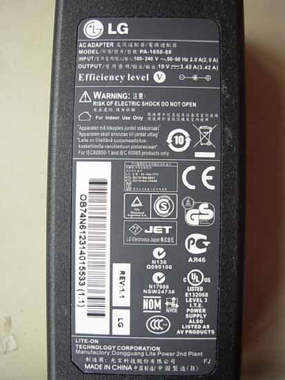
Click to zoom
Application Details
- Equipment Class
- JBP - Part 15 Class B Computing Device Peripheral
- Date of Grant
- Nov 06, 2011
- Application Purpose
- Original Equipment
- Date of Application
- Nov 06, 2011
- Equipment Note
- Part15 Subpart B-LCD Monitor
- Company
- LG Electronics USA, Inc.
- Country
- United States
Documents & Files
Document Text
Text extracted from the exhibit documents filed with the FCC. Open a document above to read the original.
Users Manual
Regulatory Information cont. FCC Compliance Statement This equipment has been tested and found to comply within the limits of a Class B digital device pursuant to Part 15 of the FCC Rules. These limits are designed to provide reasonable protection against harmful interference in a residential installation. This equipment generates, uses, and can radiate radio frequency energy and if not installed and used in accordance with the instructions, may cause harmful interference to radio communications. However, there is no guarantee that interference will not occur in a particular installation. If this equipment does cause harmful interference to radio or television reception (which can be determined by turning the equipment on and off), the user is encouraged to try to correct the interference by using one or more of the following measures: Reorient or relocate the receiving antenna. Increase the separation between the equipment and the receiver. Connect the equipment into an outlet on a circuit different from that to which the receiver is connected. Consult the dealer or an experienced radio/TV technician for help. Caution: Changes or modifications not expressly approved by the party responsible for compliance could void the user's (or your) authority to operate the equipment. Only peripherals (digital input/output devices, terminals, printers, etc.) certified to comply with the Class B limits may be attached to this monitor. Operation with non-certified peripherals is likely to result in interference to radio and TV reception. Only shielded signal cables may be used with this System. Canadian DOC Notice This Class B digital apparatus meets all requirements of the Canadian Interference-Causing Equipment Regulations. Cet appareil numérique de la classe B respecte toutes les exigences du Règlement sur le matériel brouilleur du Canada. TCO Displays 5.0 Congratulations, Your display is designed for both you and the planet! This display carries the TCO Certified label. This ensures that the display is designed for minimal impact on the climate and natural environment, while offering all the performance expected from top of the line electronic products. TCO Certified is a third party verified program, where every product model is tested by an accredited independent test laboratory. TCO Certified represents one of the toughest certifications for displays worldwide. Some of the Usability features of the TCO Displays 5.0 requirements: Visual Ergonomics Good visual ergonomics in order to improve the working environment for the user and to reduce sight and strain problems. Important parameters are: • Light levels without color tint, Uniform color and luminance, Wide color gamut • Calibrated color temperature and gamma curve • Wide luminance level, Dark black levels, Low motion blur Electrical Safety • Product fulfills rigorous safety standards 1 NOTICE The regulations are applied only to the products with the ID LABEL indicating specific requirements. NOTICE The regulations are applied only to the products with the ID LABEL indicating specific requirements. NOTICE The following information is for the models certified by TCO. If you want to know the specification of the purchased product, see the label attached on the back of the product. Regulatory Information cont. 2 Emissions • Low alternating electric and magnetic fields emissions • Low acoustic noise emissions Some of the environmental features of the TCO Displays 5.0 requirements: • The brand owner demonstrates corporate social responsibility and has a certified environmental management system (EMAS or ISO 14001) • Very low energy consumption both in on-and standby mode • Restrictions on chlorinated and brominated flame retardants, plasticizers and polymers • Restrictions on heavy metals such as cadmium, mercury and lead (RoHS compliance) • Both product and product packaging is prepared for recycling • The brand owner offers take-back options The requirements included in this label have been developed by TCO Development in co-operation with scientists, experts, users as well as manufacturers all over the world. Since the end of the 1980s TCO has been involved in influencing the development of IT equipment in a more user-friendly direction. Our labeling system started with displays in 1992 and is now requested by users and IT-manufacturers all over the world. For more information, please visit: www.tcodevelopment.com Information for Environmental Preservation LGE. announced the 'LG Declaration for a Cleaner Environment' in 1994, and this ideal has served as a guiding managerial principle ever since. The Declaration is a foundation that has allowed us to undertake environmentally friendly activities in careful consideration of economic, environmental, and social aspects. We promote activities for environmental preservation, and we specifically develop our products to embrace the concept of environment-friendly. We minimize the hazardous materials contained in our products. For example, there is no cadmium to be found in our monitors. Information for recycling This monitor may contain parts which could be hazardous to the environment. It is important that this monitor be recycled after use. LGE. handles all waste monitors through an environmentally acceptable recycling method. There are several take-back and recycling systems currently in operation worldwide. Many parts will be reused and recycled, while harmful substances and heavy metals are treated by an environmentally friendly method. If you want to find out more information about our recycling program, please contact your local LG vendor or a corporate representative of LG. We set our vision and policies on a cleaner world by selecting the issue of the global environment as a task for corporate improvement. Please visit our website for more information about our ‘green’ policies. http://www.lg.com/global/sustainability/environment/take-back- recycling.jsp English Informationen zur Erhaltung der…
Text truncated - open the document above for the full version.
Users Manual
www.lg.com OWNER'S MANUAL NETWORK MONITOR N2210WZ Please read the safety information carefully before using the product. Network Monitor Model English 2 ENG English Table of Contents TABLE OF CONTENTS 3 ASSEMBLING AND PREPARING 3 Unpacking 4 Parts and buttons 6 Setting Up the Monitor set 6 - Attaching the Stand Base 6 - Detaching the stand base 7 - Adjusting the stand height 7 - Adjusting the angle 8 - Mounting on a table 8 - Using the Kensington locking device 9 - Detaching the stand body 9 - Swivel stand 9 - Installing the wall mount plate 10 - Mounting on a wall 11 USING THE MONITOR SET 11 Connecting Input Signal Cable 11 - D-SUB IN connection - PC 11 - D-SUB OUT connection - PCoIP 12 - DVI connection - PCoIP 13 Connecting LAN/Peripherals 13 - LAN connection - PCoIP 14 - Peripheral device connection 15 - Self Image Adjustment 16 CUSTOMIZING SETTINGS 16 Accessing The Main Menus 17 MENU Settings 17 - Picture 18 - Color 19 - Display 20 - Others 21 MODE Settings 21 - F-ENGINE 22 - PHOTO EFFECT 23 AUTO Settings : D-SUB Input 23 -/ /- Settings : PCoIP Input 24 TROUBLESHOOTING 26 PRODUCT SPECIFICATION 27 Preset Mode 27 Power Indicator 28 PROPER POSTURE 28 Proper posture for using the monitor 29 USING PCOIP SOLUTION 19 - Volume 3 ENG English ASSEMBLING AND PREPARING ASSEMBLING AND PREPARING Unpacking Please check whether all the components are included in the box before using the product. If there are missing components, contact the retail store where you purchased the product. Note that the product and components may look different from those shown here. yy Only use an approved LG power adapter. yy Damage caused by other power adapters is not covered by warranty. yy Note that the components may look different from those shown here. yy Without prior notice, all information and specifications in this manual are subject to change to improve the performance of the product. yy To purchase optional accessories, visit an electronics store or online shopping site or contact the retail store where you purchased the product. Power CordUser Manual/Card Stand Base Adaptor CAUTION NOTE 15-pin D-SUB Signal Cable 4 ENG English ASSEMBLING AND PREPARING Parts and buttons Power Indicator yy LED On : Power is on yy LED Off: Power is off Front Side Buttons Input Connectors (See p.11 to 14) (Power Button) Input Connectors (See p.14 ) 5 ENG English ASSEMBLING AND PREPARING ButtonDescription MENU Activates the main menu. OSD Lock/Unlock Functions Locks/unlocks the OSD screen. y To lock the OSD screen, press and hold the MENU button for several seconds. The "OSD LOCKED" message will be displayed and the screen will be locked. y To unlock the OSD screen, press and hold the MENU button again for several seconds. The "OSD UNLOCKED" message will be displayed and the screen will be unlocked. MODEMoves to the F-ENGINE and PHOTO EFFECT options. AUTOTo adjust the monitor settings, press the AUTO button on the MONITOR SETUP OSD menu (only supported for analog signal). For optimal screen display, use the following resolution. Optimal Resolution1680 x 1050 INPUTAllows selection of the input signal. y If you connect the monitor to a computer using a D-SUB cable, select either the PCoIP or D-SUB input signal. y If only one computer is connected to the monitor, the input signal is detected automati- cally. The initial input signal is PCoIP. EXITExits the OSD menu. (Power Button) y D-SUB Input: Power On/Off y PCoIP Input Monitor Off: Press the power button twice, or press the power button and wait for 10 seconds. PCoIP Off: Press the power button, then press the EXIT button located next to the power button. PCoIP On: Press the power button. Remote PC Power Control: Press the power button for at least five seconds to turn the PC on/off. * To use the Remote PC Power Control function, separate settings are required for the PC. Power IndicatorWhen the monitor is in operating mode, the power indicator will turn white (on mode). When the monitor is in power saving mode, the power indica- tor will blink white. 6 ENG English ASSEMBLING AND PREPARING yy The components appearing in the illustra- tions may look different from the actual prod- uct. yy Do not carry the monitor upside-down as this may cause it to fall off its stand, resulting in damage or injury. yy To avoid damaging the screen when lifting or moving the monitor, only hold the stand or the plastic cover. This avoids putting unnec- essary pressure on the screen. yy Only remove the tape and the locking pin when the monitor is mounted on the stand base and is in an upright position. Otherwise, the stand body may protrude, which may lead to injury. Detaching the stand base 1 Place the monitor's screen face down. To protect the screen from scratches, cover the surface with a soft cloth. Setting Up the Monitor set Attaching the Stand Base 1 Place the monitor's screen face down. yy To protect the screen from scratches, cover the surface with a soft cloth. 3 Using a coin, turn the screw clockwise to se- cure the stand base. 2 Check the position (at the front and rear) of the stand body, then mount the stand base on the stand body as shown in the figure. Stand Body Stand Base Stand Base 2 Using a coin, turn the screw in the stand base counterclockwise. Detach the stand base from the stand body. Stand Body Stand Base CAUTION CAUTION 7 ENG English ASSEMBLING AND PREPARING yy Once the pin is removed, it is not necessary to re-insert it to adjust the height. Adjusting the stand height 1 Place the monitor mounted on the stand base in an upright position. Adjusting the angle 1 Place the monitor mounted on the stand base in an upright position. 2 Remove the tape attached at the bottom rear of the stand body, then pull out the locking pin. 3 The height can be adjusted up to 110 mm. 2 Adjust the angle of the screen. The angle of the screen can be adjusted up to 15° forwards and 5° backwards for a comfortable viewing experi- ence. yy To avoid injury to the fingers when adjusting the screen, do n…
Text truncated - open the document above for the full version.
Users Manual
21 ENG English CUSTOMIZING SETTINGS MenuAnalog (D-SUB) PCoIP Description NORMAL ●● Select this option for everyday viewing. * If F-ENGINE is not set to NORMAL, CONTRAST is disabled. MOVIE ●● Select this option when watching videos or movies. INTERNET ●● Select this option when working on a document (e.g. Microsoft Word) for a prolonged period of time. MODE Settings F-ENGINE 1 Press any button on the front of the monitor to dis- play the MONITOR SETUP OSD menu. 2 Press the MODE button to display the options in the OSD menu. 3 Set the options by pressing the buttons on the front of the monitor. 4 Select EXIT to leave the OSD menu. To return to the upper menu or set other menu items, use the up arrow () button. Each option is explained below. yy Analog: D-SUB (analog signal) input. PCoIP: Internal signal through the LAN. EXIT NORMALMOVIEINTERNET MODE 22 ENG English CUSTOMIZING SETTINGS yy Analog: D-SUB (analog signal) input. PCoIP: Internal signal through the LAN. PHOTO EFFECT 1 Press any button on the front of the monitor to dis- play the MONITOR SETUP OSD menu. 2 Press the MODE button to display the options in the OSD menu. 3 Set the options by pressing the buttons on the front of the monitor. 4 Select EXIT to leave the OSD menu. To return to the upper menu or set other menu items, use the up arrow () button. Each option is explained below. MenuAnalog (D-SUB) PCoIP Description NORMAL ●● The PHOTO EFFECT option is disabled. * If the PHOTO EFFECT option is not set to NORMAL, the CON- TRAST is disabled and the screen is in grayscale. If you choose to display the screen in color, PHOTO EFFECT will be set to NORMAL and CONTRAST will be enabled. PHOTO EFFECT and F-ENGINE cannot be enabled at the same time. GAUSSIAN BLUR ●● Displays the screen brighter and in a softer tone. SEPIA ●● Displays the screen in sepia (brown) tone. MONOCHROME ●● Displays the screen in grayscale (black and white). EXIT NORMALGAUSSIAN BLUR SEPIAMONOCHROME MODE EXIT 23 ENG English CUSTOMIZING SETTINGS 1 Press any button on the front of the monitor to dis- play the MONITOR SETUP OSD menu. 2 Press the AUTO button to automatically adjust the screen. 3 Select EXIT to leave the OSD menu. To return to the upper menu or set other menu items, use the up arrow () button. -/ /- Settings : PCoIP Input 1 Press any button on the front of the monitor to display the MONITOR SETUP OSD menu. 2 Press the button for at least three seconds to disconnect from the server. 3 Select EXIT to leave the OSD menu. To return to the upper menu or set other menu items, use the up arrow () button. Pressing the AUTO button allows the monitor to automatically optimize the screen to the current display mode. If you are not satisfied with the optimized screen, you can manually adjust the position of the display area, frequency, phase and sharpness in the OSD menu. (Only available for D-SUB [analog] signals. Note that the sharpness setting is only available for digital sig- nals.) I n PCoIP mode, press the button for at least three seconds to disconnect from the server. PROCESSING AUTO IMAGE ADJUSTMENT FOR OPTIMAL DISPLAY CHANGE RESOLUTION TO 1280 x 1024 yy What is "Auto Image Adjustment"? The Auto Image Adjustment option allows you to improve the picture quality if the screen is dimmed, if the text appears blurred or spread, if the screen flickers or if the display area is not centered after adjusting the resolution. (Only available for D-SUB [analog] signals.) NOTE AUTO Settings : D-SUB Input 24 ENG English Troubleshooting TROUBLESHOOTING Nothing is displayed on the screen Is the monitor's power cord plugged in? y Check if the power cord is correctly plugged in to the outlet. Is the power indicator on? y Check the power indicator. Is the power indicator displaying as white? y Adjust the brightness and the contrast. Is the power indicator blinking? y If the monitor is in power saving mode, move the mouse or press any key on the keyboard to switch the display on. y Check if the computer is turned on. Is the "OUT OF RANGE" message displayed? y This occurs when signals transferred from the PC (video card) are out of the horizontal or vertical frequency range of the monitor. Please see the "Product Specification" section of this manual to set the appropri- ate frequency. Is the "CHECK SIGNAL CABLE" message is displayed? y This is displayed when the signal cable between the PC and the moni- tor is missing or disconnected. Check the cable and reconnect. The "OSD LOCKED" message is displayed. Is the "OSD LOCKED" message displayed when the MENU button is pressed? y The OSD lock feature is enabled to prevent undesired modification of the OSD settings. Press and hold the MENU button for a couple of seconds to unlock the OSD. (The "OSD UNLOCKED" message will be displayed.) The screen retains an image. Does image sticking occur even when the monitor is turned off? y Displaying a still image for a prolonged time may cause damage to the screen, resulting in the retention of the image. y Use a screen saver to protect the screen when using the monitor for a prolonged period of time. yy Vertical Frequency: In order to display an image, the screen must be refreshed dozens of times per second like a fluorescent lamp. The number of times the screen is refreshed per second is called vertical frequency or refresh rate and is represented by Hz. yy Horizontal Frequency: The time it takes to display one horizontal line is called the horizontal cycle. The number of horizontal lines displayed in one second can be calculated by dividing one by the horizontal cycle. This is called horizontal frequency and is represented by kHz. NOTE 25 ENG English Troubleshooting The image is displayed abnormally. Does the display area appear un- centered? Pressing the AUTO button will automatically optimize the screen to the current display mode. If you are not satisfied with the optimized screen, you can manually adjust the POSITION option in the OSD menu. Does the screen exhibit vertical lines? Pres…
Text truncated - open the document above for the full version.
Block Diagram
LVDS 5VS K0 [Pseries Block Diagram] 2011.09.30_김현석 : Monitor Block: TERA Block 6p Scaler FE252MH TSUMU58EWHL WLED Enable WLED ADJ EEPROM LVDS 2CH 33VD K ey 0 5VN_ON 3.3V-PL SCLK / SDATA Key1PLED IC103 IC100 IC104 4ch MICOM W25X20B SCLK / SDATA 19V 3 . 3VD 1.8VD D-SCLA / D-SDAA ST R/G/B/H/V _ D-sub D-sub IN Chrontel DVI #0 Chrontel D-sub OUT 3.3V 19V_LED IC101 IC105 IC102 MAXIM MAX16814 LED Driver 4ch LED W25X20B Video #0 5V DC/DC CH7301C DVI Tx CH7301C DVI Tx R/G/B/H/V _ D-sub #0 DVI #1 R/G/B/H/V #1 DVI-I OUT Chrontel CH7301C DVI Tx 3.3V 19V EEPROM SCLK / SDATA 3.3V DC/DC IC106 IC108 IC116 IC125 DDC_CLK1 / DDC_DATA1 USB1.1 3.3V 1.275V DM/DP USB1.1 XDR DRAM 1.5V 1.275V Video #1 3.3V 1.5V DC/DC 1.5V 1 275V IC113 IC108 IC121 IC122 MITSUMI Bus Buffer level translator 3.3V 5V 3.3V Teradici TERA1100 MACRONIX MX25L6445EMI Serial Flash IC111 5VS 3.3VD USB1.1USB1.1 3.3V-PL SS K4Y12324TE 1Gbit XDR DRAM SPI 5V_IN 1 . 275V DC/DC 1.275V 3.3VS_TERA IC107 IC109 IC110 IC112 IC124 IDT ICS557G 3.3V SPI Tx/Rx 3.3V 5V 1.8V 18V APE8839 1.8VD Realtek ALC888GR Mic IN Realtek RTL8211BN RS232 Tx/Rx 3.3V 3.3V 5V 1.8V FET IC111 IC115 IC114 IC119 TI, MAX3232 RS-232 receiver CYPRESS Clock generator ICS557G EMI Clock IC PIN-Header 1.5V 2.5V 100MHz 400MHz RJ-45 Audio OUT 2.5V Regulator 1.8V Regulator 1 . 8V Headphone OUT ALC888GR HAD codec 2.5V Ethernet Magnetic IC117 Clock generator CY24272ZXC
Cover Letter(s)
Statement FCC ID: BEJN2210WZT Data: Nov 02, 2011 We LG Electronics U.S.A., Inc. declare under our own responsibility that the product LCD Monitor to which this declaration refers conforms with all electrical and mechanical devices employed for spurious radiation suppression, including any modifications made during certification testing, must be incorporated in each unit marked. 2011.11.02 [Data] [Name and Signature of person responsible]
Cover Letter(s)
Power of Attorney Federal Communication Commission Office of Engineering and Technology Equipment Authorization Division 7345 Oakland Mills Road Columbia, Maryland 21046 We, Company: LG Electronics U.S.A., Inc. Address: 1000 Sylvan Avenue, Englewood Cliffs, NJ 07632 Would like to inform you that we nominated Audix Technology (Shanghai) Co., Ltd, Mr. Byron Kwo to act on behalf of our LG Electronics Inc. to apply FCC ID for the LCD Monitors with LG brand. Kind Regards, Place, date Signature 2011-11-02 Christopher Johnson ________________ ________________
External Photos
FIGURE 1 LCD MONITOR (M/N: N2210WZT) GENERAL APPEARANCE (FRONT VIEW) F IGURE 2 LCD MONITOR (M/N: N2210WZT) GENERAL APPEARANCE (BACK VIEW) FIGURE 3 LCD MONITOR (M/N: N2210WZT) BOTTOM PORTS F IGURE 4 LCD MONITOR (M/N: N2210WZT) SIDE PORTS FIGURE 5 LCD MONITOR (M/N: N2210WZT) D-SUB CABLE #2 FIGURE 6 LCD MONITOR (M/N: N2210WZT) ADAPTER (GENERAL APPEARANCE – FRONT VIEW) F IGURE 7 LCD MONITOR (M/N: N2210WZT) ADAPTER (GENERAL APPEARANCE – BACK VIEW) FIGURE 8 LCD MONITOR (M/N: N2210WZT) ADAPTER (GENERAL APPEARANCE – LABEL) FIGURE 9 LCD MONITOR (M/N: N2210WZT) ADAPTER (AC PORT)
ID Label/Location Info
Label Location Information Refer to the below red arrow: (For example)
Internal Photos
FIGURE 1 LCD MONITOR (M/N: N2210WZT) COVER REMOVED F IGURE 2 LCD MONITOR (M/N: N2210WZT) LABEL ON LCD PANEL FIGURE 3 LCD MONITOR (M/N: N2210WZT) MAIN BOARD (COMPONENT SIDE) F IGURE 4 LCD MONITOR (M/N: N2210WZT) MAIN BOARD (COMPONENT SIDE) FIGURE 5 LCD MONITOR (M/N: N2210WZT) CHIP #1 & CRYSTAL #1 ON MAIN BOARD F IGURE 6 LCD MONITOR (M/N: N2210WZT) CHIP #2 & CRYSTAL #2 ON MAIN BOARD FIGURE 7 LCD MONITOR (M/N: N2210WZT) CHIP #3 & CRYSTAL #3 ON MAIN BOARD FIGURE 8 LCD MONITOR (M/N: N2210WZT) KEY BOARD (COMPONENT SIDE) F IGURE 9 LCD MONITOR (M/N: N2210WZT) KEY BOARD (SOLDERED SIDE) FIGURE 10 LCD MONITOR (M/N: N2210WZT) LCD PANEL CONTROL BOARD (COMPONENT SIDE) F IGURE 11 LCD MONITOR (M/N: N2210WZT) LCD PANEL CONTROL BOARD (SOLDERED SIDE) FIGURE 12 LCD MONITOR (M/N: N2210WZT) DEBUG #1 F IGURE 13 LCD MONITOR (M/N: N2210WZT) DEBUG #2 FIGURE 14 LCD MONITOR (M/N: N2210WZT) DEBUG #3
Operational Description
LG Electronics U.S.A., Inc. FCC ID: BEJN2210WZT 1 Equipment Description The Equipment Under Test (EUT) is the LG Electronics U.S.A., Inc. LCD Monitor. General Specification LG Electronics U.S.A., Inc. FCC ID: BEJN2210WZT 2 EUT Operating Conditions a. Setup the EUT and Peripherals as shown in Sec. 3.2 of the test report. b. Turn on the power of all equipment and the EUT. c. Set the contrast & brightness of EUT to maximum. d. PC system ran the self-test program "EMC Test" by windows XP and sent "H" characters to EUT through graphic card (we use white letters on a black background to represent all colors), the EUT's screen displayed and filled with "H" pattern by its resolution (Via D-Sub Input). e. In PCoIP mode, the PC connected with the EUT through LAN port and transmit video signal. The EUT then display "H" pattern. f. Repeat above procedure from c to e for difference test mode. g. The other peripherals devices were driven and operated during the test. h. The test modes are as follows: Test Mode D-Sub 640*480@60Hz D-Sub 1280*1024@60Hz D-Sub 1680*1050@60Hz PCoIP
Schematics
USB DOWN STREAM THERMAL USB DOWN STREAM THERMAL THERMAL YELLOW THE SYMBOL MARK OF THIS SCHEMETIC DIAGRAM INCORPORATESSPECIAL FEATURES IMPORTANT FOR PROTECTION FROM X-RADIATION.FILRE AND ELECTRICAL SHOCK HAZARDS, WHEN SERVICING IF IS ESSENTIAL THAT ONLY MANUFATURES SPECFIED PARTS BE USED FORTHE CRITICAL COMPONENTS IN THE SYMBOL MARK OF THE SCHEMETIC. C5050.1uF PDATA0_11 R48910K READY DVI1_TD0N_J CONFIG2 R429 33K 1% HPD0 BLU C5000.1uF R28310K R5371K C156 0.1uF R34140.2 1% X101 25MHz R139 75 R526 100K C1760.1uF50V SPI_SSB_F DQ_0P_5 R388 22 R4024.7K 3.3V C1520.1uF TXD0 DVI0_TD0P_J R135 0 R2762.2K SCLK 3.3V-PL C10310uF10V R48610K PDATA0_DVI_10 R390 0 READY R449 3.4K 1% DVI0_TDCP C266 0.1uF R493 100K PDATA1_1 C3340.1uF C232 0.1uF GPIO_14 JP133 C4560.1uF TXEN COL DVI0_TD0N CONFIG0 C1280.1uF C4140.1uF PDATA1_DVI_7 C14615pF50V PDATA1_6 USB_PWRPRT3 2.5V C1160.1uF Q109KTN2222AS E B C C57610uF10V DVI0_TD1N R394 4.7K DQ_0N_0 C3810.1uF HPD0_BUFFER L142 CIC21J601 C171 0.1uF R437 1.5K 3.3V R444 22 R496100K X102 25MHz C2710.1uF SPI_TXD R413 22 R123 75 DVI0_G_OUT SPI_TXD_F 1.275V_RSL R287 4.7K READY Q101KTN2222AS READY E B C CONFIG2 3.3V C3160.1uF AR10539 CRS C112 0.047uF C385100pF50V R2981K X100 14.31818MHz C5160.01uF25V TRD2_N R451 10K R370 4.7K READY R282 33.2 1% PDATA0_10 DVI1_TVDD C475100pF50V DM3 C2760.1uF C4880.1uF R289 10K SRD C4470.1uF C14822pF50V READY 3.3VD CLKOUTM-B RXER 3.3V PDATA0_1 PDATA0_DVI_2 L143 UBW2012-301 C3490.1uF L155 ACM2012-900H-2P 12 34 PDATA0_DVI_6 C1992.2uF100V R221 100 READY DQ_0P_4 R385 4.7K C358 0.1uF DVI1_G_OUT Y0P-B C1951uF10V R412 22 R465 0 READY C1972.2uF16V PCLK0_P C2540.1uF C55047pF50V READY D103 IP4223CZ6_07_06_26 3 2 4 1 6 5 C4130.1uF AUDIO_FRONT_JD_CC43022pF50V READY R512 100K R396 4.7K DVI1_DVDD R277 4.7K Y1P-B COL DDC_CLK0 3.3V 1.8V C3881uF10V CONFIG1 SPI_CLK_F TXER L127 ACM2012-900H-2P 12 3 4 GPIO6 IC116 APW7080KAI-TRL 3 UGND 2 EN 4 VCC 1 VIN 5 LX 6 COMP 7 FB 8 GND L160 MLB-201209-0120P-N2 C27510uF10V PDATA0_4 CFMP C5370.1uF Y1P-A R419 12K 1% READY SPI_CLK DVI0_TVDD C2470pF50V CMD XCG_CLK_P R379 22 BLU C247 0.1uF XDRDRAM_CLK_N Y3P-A R105 56 R2732.2K 5V C18422pF50V READY EPHY_INTB/CONFIG7 5V R527 100K C3220.1uF C3040.1uF RQ_5 D100 KDS226 READY A AC C R28133 RQ_1 3.3V RXD4 C2150.1uF16V C39910uF10V PDATA1_DVI_10 RQ_2 3.3V-PL R474 22R475 22 CONFIG4 C5780.068uF50V TCK L139 BLM18BB470SN1D C3020.1uF PDATA1_9 PDATA0_DVI_3 L101 BLM18BB470SN1D C1600.1uF 2.5V 3.3V R197 14K1% C17410pF50V DVI1_TD0P DQ_1N_0 C19247pF 50V TRD0_P GPIO22 EPHY_MDC Y0M-A C2570.1uF SPI_SSB PDATA0_9 C3060.1uF L133 BG2012B221 PCSPKR 1.275V R150 0 R426 30K 1% READY R183 33 DVI0_R_OUT C55547pF50V READY TCK C4910.1uF R303100K R480 0 READY CLKOUTM-A C142 68pF C2600.1uF R4181M READY C3330.1uF C4460.1uF C246 0.1uF PDATA1_5 3.3V C1980.1uF16V READY RXD6 R32810K 3.3VD RXD2 C3570.1uF D113 IP4223CZ6_07_06_26 32 4 1 6 5 DQ_1N_3 C384100pF50V R461 1K R49410K READY C5141000pF50V XCG_CLK_N RQ_11 R400 4.7K READY IC102 M24C02-RMN6T 3 E2 2 E1 4 VSS 1 E0 5 SDA 6 SCL 7 WC 8 VCC L141 UBW2012-121F C1000.1uF READY C3380.1uF C38910uF10V L132 BG2012B221 R439 22 C496 1uF 1.275V DQ_0P_7 DDC_CLK0 R32610K TRD0_P DM2 R399 4.7K READY HPD0_J DVI1_TD2N VBUS0 C4230.1uF R286 10K C222 100uF 16V CMD PDATA0_7 R344 49.9 1% DVI1_TD1N_J 3.3V C5811uF25V DVI1_B_OUT PDATA1_DVI_7 C4970.1uF AUDIO_MIC1_VEFOR_C C2650.1uF R336 100 C187 0.1uF C523 220uF 16V Y3M-B RST L110 ACM2012-900H-2P 12 3 4 C3130.1uF R395 4.7K R3474751% 1608 DQ_0P_3 C3650.1uF P105 YFDW254-10S 123456789 10 PDATA1_DVI_1 R403 0 READY GPIO23 Y2P-B CONFIG0 C2201uF10V 3.3VS_TERA DQ_1P_1 RQ_3 C181 0.1uF RQ_6 HPD0_BUFFER R504 100K C436 10uF 10V TXD1 3.3V RQ_VREF R420 200R421 200 PDATA0_0 5V AUDIO_SURRR_C L_SPK_OUT+ 5V_IN DM3 R29910K READY RQ_VREF C1070.1uF C3730.1uF R48710K 5V R446 22 C5120.01uF25V 1.5V EPHY_MDIO R292 4.7K READY C3240.1uF C134 68pF C480100pF50V C368100pF50V R482 0 READY Y0M-B 3.3V PDATA0_DVI_0 X103 24MHz 3.3V R447 22 C115 0.047uF DQ_1P_5 R360 39K1% READY DVI1_TD2P DDC_CLK1_5V C57410uF10V PDATA0_2 DQ_1P_3 5V_ESD R220 100 READY R2651K R5323.3K1% R2320 C5150.01uF25V L104 BG2012B221 C528 2200pF 50V 19V_LED C21239pF 50V C3640.1uF C18922pF50V READY KEY1 RXD1 RXD4 R100 1K READY PDATA1_7 1V275_PWRGD PDATA1_DVI_10 C3440.1uF C40610uF10V DSUB_SDA PCLK1_P_DVI C2970.1uF R302100K C213 2.2uF100V C3190.1uF R169 10K 3.3V DVI0_TD2N_J DVI1_TD2P_J RQ_9 DVI0_H_OUT RST CRS R162 39 AUDIO_SURR_JD_C RQ_4 R473 22 C1940.47uF50V READY C1040.1uF READY OCB0 PDATA1_0 C1080.1uF PDE1 C240 0.1uF WLED_DIM_ADJ HPD1_BUFFER WLED_STATUS DVI0_VREF C5751uF10V D110 KDS226 A AC C AR100 39 3.3V-PL XDRDRAM_CLK_P 1.5V Y1M-A C4080.1uF C3740.1uF RQ_11 Q106 KST3906-MTF E B C 19V 2.5V PDE0_DVI L109 ACM2012-900H-2P 12 3 4 DQ_1P_7 L126 ACM2012-900H-2P 12 3 4 C4350.1uF DVI0_TD1N_J C183 0.1uF R434 0 PDATA1_4 C207 1000pF 50V RQ_4 R523 100K R143 100 READY R192 39 DVI1_TDCN DVI1_H_OUT C3620.1uF CONFIG1 RQ_2 PDE0_DVI AUDIO_MIC1_VEFOL_C DVI1_TD1P C13810pF50V C312pF50V 3.3VS_TERA 5V R445 22R440 22 C4410.1uF C561100uF16V IC121 BD9130EFJ-E2 3 ITH 2 VCC 4 GND 1 ADJ 5 PGND 6 SW 7 PVCC 8 EN C162100pF50V EPHY_INTB/CONFIG7 L102 BLM18BB470SN1D C3250.01uF50V C3360.1uF C416220uF16V READY R381 22 MODON C3590.1uF VSYNC1 RQ_1 C113 1000pF R174 10K TXD5 C4450.1uF DVI0_TVDD DVI0_TD0P RXD7 R216 0 L158 4.7uH R518 100K C511 68pF R172 0 READY R156 20K R2340 19" R36710K DDC_DATA0_SCLR AUDIO_SDI R187 715 C1250.1uF PDATA1_5 R11710K READY C55747pF50V READY AUDIO_FRONT_L_C DQ_1N_3 LD102BL-HB535A-AV-TRB R165 33 P_LED DVI0_TD2P RQ_8 C5711uF25V PDATA1_8 R103 56 EPHY_RESETB TXD7 P1 SMAW200-06 123456 3.3VD PDATA1_DVI_11 R279100K PCLK0_N_DVI L148 CIC21J601 C53622pF50V DVI0_TD0N_J RS232_TX PDATA1_DVI_6 C3320.01uF50V R374 4.7K R49110K READY R142 100 READY PDATA1_DVI_8 R262 0 R533 10K 1% 1/10W R191 39 C5200.1uF RQ_0 C4480.1uF 2.5V_VDDP_CLK R133 0 C55847pF50V READY R223 100 READY R47810K WLED_ENABLE R148 0 READY DQ_0P_1 OCB1 RXER Y0M-B DQ_0N_7 R11110K READY R125 140 1% C1200.1uF C3170.1uF 3.3V TRD3_P C40010uF10V SDATA R153 4.7K R325100 DVI1_TD0P_J L146 MLB-201209-01…
Text truncated - open the document above for the full version.
Test Report
LG Electronics U.S.A., Inc. FCC ID: BEJN2210WZT Page 1 of 29 Audix Technology (Shanghai) Co., Ltd. Report No.: ACI-F11150 Prepared For : LG Electronics U.S.A., Inc. 1000 Sylvan Avenue, Englewood Cliffs, NJ 07632, United States Prepared By : Audix Technology (Shanghai) Co., Ltd. 3F and 4F 34Bldg 680 Guiping Rd, Caohejing Hi-Tech Park, Shanghai 200233, China Tel: +86-21-64955500 Fax: +86-21-64955491 Report No. : ACI-F11150 Date of Test : Oct 10 – 25, 2011 Date of Report : Oct 28, 2011 Application for FCC Certificate On Behalf of LG Electronics U.S.A., Inc. LCD Monitor Model No.: N2210WZT Serial No.: E11101247-01/01 FCC ID : BEJN2210WZT LG Electronics U.S.A., Inc. FCC ID: BEJN2210WZT Page 2 of 29 Audix Technology (Shanghai) Co., Ltd. Report No.: ACI-F11150 TABLE OF CONTENTS Page 1 SUMMARY OF STANDARDS AND RESULTS .......................................................................... 4 1.1 Description of Standards and Results .....................................................................…
Text truncated - open the document above for the full version.
Contact Information
Applicant
David Kim(Team leader, LGEUS NA Policy & Regulatory Affairs)
Technical Contact
Audix Technology (Shanghai) Co., Ltd.Kwo Byron
+86-21-64955500
3F 34Bldg 680 Guiping Rd., Caohejing Hi-Tech Park · Shanghai · China
Test Firm
Audix Technology ( Shanghai ) Co., Ltd.Byron Kwo
Technical Specifications
| # | Rule Parts | Frequency Range | Power Output |
|---|---|---|---|
| 1 | 15B | - | - |
Other Applications from LG Electronics USA, Inc.

BEJTFHOBINI1F1
Jan 08, 2025Telematics
Equipment Class
DTS - Digital Transmission SystemBEJNT-16Z90TS
Oct 02, 2024Notebook Computer
Equipment Class
DSS - Part 15 Spread Spectrum TransmitterBEJSP-PEW8
Sep 26, 2024Stylus Pen
Equipment Class
DCD - Part 15 Low Power Transmitter Below 1705 kHzBEJ-RSMV2
Sep 24, 2024RF Module
Equipment Class
FDS - Part 15 Field Disturbance SensorBEJTFBMEIBN3EU
Sep 24, 2024Telematics
Equipment Class
NII - Unlicensed National Information Infrastructure TX