BEJRD3330CDMA Cellphone
LG Electronics USA, Inc.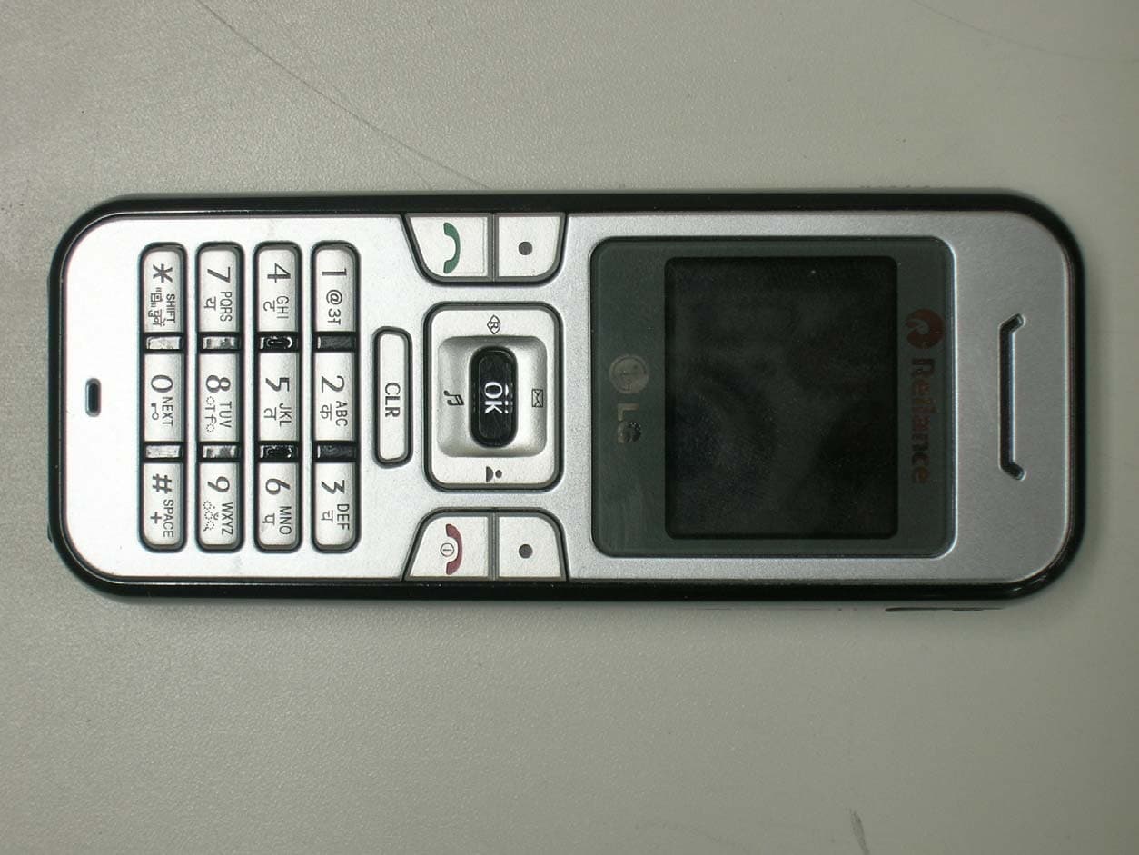
Click to zoom
Application Details
- Equipment Class
- TNE - Licensed Non-Broadcast Transmitter Held to Ear
- Date of Grant
- Jan 02, 2006
- Application Purpose
- Original Equipment
- Date of Application
- Jan 02, 2006
- Equipment Note
- CDMA Cellphone
- Frequency Range
- 824.70000000 - 848.31000000
- Company
- LG Electronics USA, Inc.
- Country
- United States
Documents & Files
Document Text
Text extracted from the exhibit documents filed with the FCC. Open a document above to read the original.
Users Manual
Operating Manual LG-RD3330 User Guide CDMA PHONE Contents Introduction Highlights Important Information Check Accessories Before You Start FCC RF EXPOSURE INFORMATION Chapter 1. Getting Started Cautions Phone Overview On screen Icons Chapter 2. Basic Functions Turning the Phone On and Off Making a Call Correcting Dialing Mistakes Receiving Calls Emergency Dialing Speed Dialing Phone Book Features Chapter 3. Menu Features General Guidelines to MENU Access and Settings Names Messages Call History Profiles Setting Planner System Chapter 4. Book Features Names Chapter 5. Message Features Write Message Inbox Outbox Voice Mail Archive Draft Templates Erase Messages Settings Chapter 6. Functions used during a call Scratch pad Mute Voice Privacy Send my number Short DTMF Chapter 7. Accessories Appendix. RF Exposure Statement Appendix 2. Consumer Information on SAR Chapter 1. Getting Started Cautions z Using the phone in proximity to receiving equipment (i.e., TV or radio) may cause interference. z Keep your phone in a safe place when not in use. z Only use the batteries, antennas, and chargers provided by LG. Using the wrong accessories could void your warranty. z Only authorized personnel should service the phone and its accessories. Faulty installation or service may result in accidents and consequently invalidate the warranty. z Do not hold the antenna while the phone is in use. z Do not use the phone in designated “no cellular phone use” areas. z Do not expose the phone to high temperature or humidity. z Avoid getting your phone wet. If the phone gets wet, turn the power off immediately and remove the battery pack. If the phone is mal-functional, return it to the dealer for service. z Avoid shock or impact on the phone. Phone Overview Function Key Descriptions Lamp The light goes on when you use the power key to turn on the phone and when there are incoming calls and messages. LCD screen Displays messages & indicator icons. END/PWR Used to turn power on/off. This key disconnects a call. Using this key, you can also exit out of a menu back to the phone’s standby display without changing the setting. SEND Allows user to place or answer calls. Mouse Key This mouse key allows quick access to text and voice mail notification messages. Profiles, R- World, and RingTone menu. And these keys are used to scroll through the memory locations and menu items. Alphanumeric Keypad These keys enable you to enter numbers and characters and choose menu items. Soft Keys The current operation of a soft key is defined by the word at the bottom of the display. Soft Keys 2 : If you press this key once in a menu, you can go back one level and if you press and hold the key in a menu, you can go back to the standby display. OK Key This key enables you to choose one item in the menu list. If you press this key in idle, mobile will show you the ‘My menu’ selection window. Star/Pound Key - In the standby status, set the manner mode by pressing the [ * ]button. (for 2 seconds) - In the standby status, set the lock function by pressing the [ # ]button. (for 2 seconds) Clear Key This key erase character and In the standby status, you can go MyMenu On screen Icons The phone screen displays several onscreen icons and onscreen icons appears when the phone is power on. Icons Descriptions Displays the strength of the signal received by the phone and current signal strength is indicated as the number of bars displayed on the screen. No service The phone is not receiving a system signal. In use A call is in progress. No icon indicates the phone is in standby mode. Digital indicator Digital service is available. Analog indicator Analog service is unavailable Indicates that a text message or voice mail has been received Roaming The phone is outside of its home service area. Charge level Indicates battery charge level. D Chapter 2. Basic Functions Turning the Phone On and Off Turning the Phone On 1. Install a charged battery pack or connect the phone to an external power source such as the cigarette lighter adapter or car kit. 2. Press [END/PWR] for a few seconds until the LCD is on. <Note> Like any other radio device, avoid any unnecessary contact with the antenna while your phone is on. Turning the Phone Off 1. Press and hold until display screen will be turned off, and then release the key. Making a Call When you make a call, follow these simple steps: 1. Make sure the phone is turned on. z If not, press [END/PWR]. 2. Enter the phone number with area code, if needed. 3. Press [SEND]. z If the phone is locked, enter the lock code. z “Call Failed” indicates that the call did not go through. 4. Press [END/PWR] to disconnect the call. Correcting Dialing Mistakes If you make mistakes in dialing a number, press [CLR] key once to erase the last entered digit or hold down [CLR] for at least two second to delete all digits, or simply press soft key 2 [BACK] to exit dialing state. Receiving Calls 1. When the phone rings, press any key (except [END/PWR], [5][6], [3((]) to answer. z If you press the key [END/PWR] once when you receive a call, you can hold the present call and ring sound or vibration stops. If you press the [END/PWR] key twice, the present call is terminated. 2. Press [END/PWR] to disconnect the call. In call waiting mode, the present call is on hold as you answer another incoming call. This service is provided by your service provider. When the call waiting function is activated, your phone will beep to let you know if you have an incoming call. Your phone may also display the incoming caller’s identification. Dialing a call from Phone Book You can place a call from any memory location either by speed dialing or by pressing [SEND] while looking up the memory location. One-Touch Dialing : One-touch dialing is a convenient feature which enables you to dial frequently used numbers in your speed-dial data by pressing a key . z Entry 9 is designated to Emergency Call. z For locations 1 to 8, you can use one-touch dialing (if enabl…
Text truncated - open the document above for the full version.
Cover Letter(s)
Aug 8. 2005 Federal Communication Commission Equipment Authorization Branch 7435 Oakland Mills Road Columbia, MID 21046 In re : LG Electronics Inc.. FCC ID: BEJRD3330 Single - Mode Cellular Phone (CDMA) Part 22 Certification Request for Confidentiality Gentlemen: In accordance with 0.459 of CFR 47, LG Electronics, Inc. hereby requests confidentiality of the Block Diagram, Schematic Diagrams, Operational Description, Technical Specification, Parts List, and Tune-Up Procedure for the above-referenced certification application. These documents contain detailed system and equipment description and related information about the product which LG Electronics Inc. Considers to be proprietary, confidential, and a custom design and, otherwise, would not release to the general public. Since this design is a basis from which future technological products will evolve, LG Electronics Inc. considers this information to be of benefit to its competitors, such that the disclosure of the information in these documents would give competitors an unfair advantage in the market. Sincerely, E.S.Park Chief Research Engineer CDMA Handset Lab LG Electronics Inc. Tel : 82- 2- 850-3850 Fax : 82- 2- 850-3855 [email protected] 459- 9, Kasan-dong,Kemchun-ku Seoul 153- 023, Korea LG Electronics Inc. LGE
Cover Letter(s)
Aug 8, 2005 Federal Communications Commission Authorization and Evaluation Div. Equipment Authorization Branch 7435 Oakland Mills Road Columbia, MD 21046 In re: LG Electronics Inc. FCC ID: BEJRD3330 Request for Short-Term Confidentiality To Whom It May Concern: In accordance with 0.457 and 0.459 of CFR 47, LG Electronics Inc. requests short-term confidentiality for the test setup photos, external photos, internal photos, and user’s manual of the attached test report. These documents contain detailed system and equipment descriptions and related information about the product, which LG Electronics Inc. considers to be proprietary, confidential, and a custom design and otherwise, would not release to the general public. Since this design is a basis from which future technological products will evolve, LG Electronics feels that this information would be of benefit to its competitors, and that the disclosure of the information in these documents would give our competitors an unfair advantage in the market. Sincerely, E.S.Park Chief Research Engineer LG Electronics Inc. LG Electronics Inc. LGE Tel : 82-2-850-3850 Fax : 82-2-850-3861 [email protected] 459-9, Kasan-dong, Kemchun-ku Seoul 153-023, Korea
Cover Letter(s)
American Telecommunications Certification Body Inc. 6731 Whittier Ave, McLean, VA 22101 January 2, 2006 RE: LG Electronics FCC ID: BEJRD3330 I have a few comments on this Application. Depending on your responses, kindly understand there may be additional comments. 1.) Rule 15.19(a)(1) requires that “...Receivers associated with the operation of a licensed radio service, e.g., FM broadcast under part 73 of this chapter, land mobile operation under part 90, etc., shall bear the following statement in a conspicuous location on the device: ‘This device complies with part 15 of the FCC Rules. Operation is subject to the condition that this device does not cause harmful interference.’ ” The required compliance statement appears is missing from the label, nor does it appear in the Manual. Please provide the exact artwork as this device will be labeled. 2.) Page 4 of the Test Report indicates that this is a ‘CDMA-FM’ device. If so, then am I to assume that AMPS-FM is also an operational mode for this equipment? If so, kindly present AMPS-FM test data and revise your Form 731. 3.) The Manual indicates this device can be connected to a computer via a data cable (page 17). Was this equipment tested as a “Computer Peripheral”? If so, then either DofC or Certification as a Class B Computer Peripheral may apply. If DofC then the FCC logo should appear on the label. Your comments please? 4.) The SAR report indicates that five different models are covered by this one SAR report. What are the different features which distinguish these models? Were all models tested for SAR compliance? 5.) Photographs showing the placement against the phantom showing both the head and body positions during SAR testing are missing from the RF Exposure exhibit. In addition, a photograph showing the minimum 15cm tissue depth is missing too. Kindly revise or supplement your SAR report. 6.) Please provide a photograph of the holster used during SAR testing. Please confirm if it does/does not contain any metal. William H. Graff President and Director of Engineering mailto: [email protected] The items indicated above must be submitted before processing can continue on the above referenced application. Failure to provide the requested information may result in application termination. Correspondence should be considered part of the permanent submission and may be viewed from the Internet after a Grant of Equipment Authorization is issued. Please do not respond to this correspondence using the email reply button. In order for your response to be processed expeditiously, you must submit your documents through the AmericanTCB.com website. Also, please note that partial responses increase processing time and should not be submitted. Any questions about the content of this correspondence should be directed to the sender.
ID Label/Location Info
FCC ID: BEJRD3330 SINGLE BAND, SINGLE MODE CDMA MOBILE PHONE LG Electronics Inc.
RF Exposure Info
Ͳͽ ͅʹͲͿ΅͑ͿͲ;Ͷ͑͗͑Ͳ͵͵Ͷ ́ ́͑ͫ ͵Ͳ΅Ͳ͑͗͑ͽʹͲ΅ ͅͿ͑ͷ͑΅Ͷ ́΅ ͅͿ ͽ͑ͶΝΖΔΥΣΠΟΚΔΤ͑ ͅΟΔ͟ ͵ΒΥΖΤ͑ΠΗ͑ΥΖΤΥΚΟΘ͑ͫ͑ͣͦ͑͑ͣͣ͑͢͢͡͡͠ί͑ͣͦ͢͠ ΅ΖΤΥ͑ ́ΚΥΖ͑ͫ͑Ͷ ́΅Ͷʹ͑ʹΠ͑͟͝ͽΥΕ͑͟ͼΠΣΖΒ ΅ΖΤΥ͑͵ΖΧΚΔΖ͑ͫ͑ ΅ΖΤΥ͑ΣΖΡΠΣΥ͑ΟΠ͑ͫͿΦΞΓΖΣ͑ΠΗ͑ΡΒΘΖ͑ͫ ʹΠΟΥΒΔΥ͑ΡΖΣΤΠΟ͑ͫΖΤΡΠΟΤΚΓΝΖ͑ΥΖΤΥ͑ͶΟΘΚΟΖΖΣ͑ͫ ͲΡΡΝΚΔΒΟΥ͑΅ΪΡΖ͑ͫ ͷʹʹ͑ʹͽͲ ́ ́ ͅͷ ͅʹͲ΅ ͅͿ͑ͫ ͷʹʹ͑ΦΝΖ͑ΒΣΥ͙Τ͚ ΅ΖΤΥ͑ΣΖΤΦΝΥΤ͑ͫ͑ ͵ΒΥΖ͑ΒΟΕ͑ ́ΚΘΟΒΥΦΣΖΤ͑ͫ͑ ͣͦͣͦ͢͡͡͠͠ ΖΡΠΣΥ͑ΣΖΡΒΣΖΕ͑ͳΪ͑ͫ͑ ͶΟΘΚΟΖΖΣ͑͠ͼ͟͟ͼΒΟΘ ͙ ́ΚΘΟΒΥΦΣΖ͚ ;ΒΟΒΘΖΣ͑ͶΟΘΚΟΖΖΣ͑͠ͻΒΪ͑ͼΚΞ ͙ ́ΚΘΟΒΥΦΣΖ͚ {GGGaGlz{zhyW\XYTWWZ ͷʹʹ͑ ͅ͵͑ͫ͑ͳͶͻ͵ͤͤͤ͡ΈΖΓ͑ͫ͑ΨΨΨ͑͟ΖΤΥΖΔΙ͑͟ΔΠ͑͟ΜΣ͑͑͑͑͑͑͑ΒΘΖ͑͑͢ΠΗ͑ͣͣ ͑͑΅ΙΖ͑΅ΖΤΥΖΕ͑ΕΖΧΚΔΖ͑ΔΠΞΡΝΚΖΤ͑ΨΚΥΙ͑ΥΙΖ͑ΣΖΦΚΣΖΞΖΟΥΤ͑ΚΟ͑ΣΖΤΡΖΔΥ͑ΠΗ͑ΒΝΝ ΡΒΣΒΞΖΥΖΣΤ͑ΤΦΓΛΖΔΥ͑ΥΠ͑ΥΙΖ͑ΥΖΤΥ͑͟΅ΙΖ͑ΥΖΤΥ͑ΣΖΤΦΝΥΤ͑ΒΟΕ͑ΤΥΒΥΖΞΖΟΥΤ͑ΣΖΝΒΥΖ͑ΠΟΝΪ ΥΠ͑ΥΙΖ͑ΚΥΖΞΤ͑ΥΖΤΥΖΕ͑͟΅ΙΖ͑ΥΖΤΥ͑ΣΖΡΠΣΥ͑ΤΙΒΝΝ͑ΟΠΥ͑ΓΖ͑ΣΖΡΣΠΕΦΔΖΕ͑ΣΖΔΖΡΥ͑ΚΟ͑ΗΦΝΝ͝ ΨΚΥΙΠΦΥ͑ΨΣΚΥΥΖΟ͑ΒΡΡΣΠΧΒΝ͑ΠΗ͑ΥΙΖ͑ΝΒΓΠΣΒΥΠΣΪ͟ ͅͶͶͶ͑ͦͣͩͣ͢͞͡͡Ή͑͵ΣΒΗΥ͑ͧͥ͟ ΖΔΠΞΞΖΟΕΖΕ͑ΣΒΔΥΚΔΖ͑ΗΠΣ͑͵ΖΥΖΣΞΚΟΚΟΘ͑ΥΙΖ͑ΖΒΜ͑ ́ΡΒΥΚΒΝ͞ͲΧΖΣΒΘΖ͑ ́ΡΖΔΚΗΚΔ ͲΓΤΠΣΡΥΚΠΟ͑ΒΥΖ͙ ́Ͳ͚͑ΚΟ͑ΥΙΖ͑ΦΞΒΟ͑ͳΠΕΪ͑͵ΦΖ͑ΥΠ͑ΈΚΣΖΝΖΤΤ͑ʹΠΞΞΦΟΚΔΒΥΚΠΟΤ ͵ΖΧΚΔΖ͑ͫ͑ͶΩΡΖΣΚΞΖΟΥΒΝ͑΅ΖΔΙΟΚΦΖΤ ͽΚΔΖΟΤΖΕ͑ͿΠΟ͞ͳΣΠΒΕΔΒΤΥ͑΅ΣΒΟΤΞΚΥΥΖΣ͑ΖΝΕ͑ΥΠ͑ͶΒΣ͙͑΅ͿͶ͚ ηͣͪͤͬ͑͟͢͡ͷʹʹ͠Ͷ΅͑ͳΦΝΝΖΥΚΟ͑ͧͦ͑ ́ΦΡΡΝΖΞΖΟΥ͑ʹ͙͑ͻΦΝΪ͚͑ͣ͢͡͡ ͼ͟͟ͼΒΟΘʹΙΖΠΝ͞ΠΠ͑ͽΖΖ ʹΖΣΥΚΗΚΔΒΥΚΠΟ ΅ΖΤΥΚΟΘ͑ΙΒΤ͑ΓΖΖΟ ʹΒΣΣΚΖΕ͑ΠΦΥ͑ΚΟ ͲΔΔΠΣΕΒΟΔΖ͑ΨΚΥΙ͑ͫ ́Ͳ͑ʹΠΞΡΝΚΒΔΖ͑΅ΖΤΥ͑ΖΡΠΣΥ Ͷ ́΅ ́Ͳͦͣͤͣͣ͢͡͞͡͡ ͥͦͪͪ͑͞͝ͼΒΤΒΟ͞ΕΠΟΘ͑͝ͼΖΦΞΔΙΦΟ͞ΜΦ͝ ́ΖΠΦΝ͑ͦͤͣͤ͑͢͞͡͝ͼΠΣΖΒ ;ΠΕΖΝΤ͑ͫ͑͵ͤͤͤ͑͡͝ ́͵ͤͤͤ͑͡͝;͵ͩ͑͢͡͝Ͳ͵ͤͤͤͦ͑͝͵ͤͤͤ͡ ͷʹʹ͑ ͅ͵͑ͫ͑ͳͶͻ͵ͤͤͤ͡ ΅ΊͶ͑ͫ͑ ́ΚΟΘΝΖ͞ͳΒΟΕ͑ ́ΚΟΘΝΖ͞;ΠΕΖ͑ʹ͵;Ͳ͑ ΙΠΟΖ͙͑ΣΠΥΠΥΪΡΖ͚ 1. SUMMARY FOR SAR TET REPORT --------------------------------------------------------------------- ͤ 1.1 Head Configuration ----------------------------------------------------------------------------------------- - ͤ 1.2 Body Worn Configuration --------------------------------------------------------------------------------- - ͤ 1.3 Measurement Uncertainty -------------------------------------------------------------------------------- - ͤ 2. INTRODUCTION ----------------------------------------------------------------------------------------------- - ͥ 3. DESCRIPTION OF THE DEVICE UNDER TEST ------------------------------------------------------ ͦ 3.1 Antenna Description ---------------------------------------------------------------------------------------- ͦ 3.2 Device Description ------------------------------------------------------------------------------------------ - ͦ 3.3 Battery Option ------------------------------------------------------------------------------------------------ ͦ 4. TEST CONDITIONS ------------------------------------------------------------------------------------------- - ͧ 4.1 Ambient Conditions ----------------------------------------------------------------------------------------- ͧ 4.2 RF Characteristics of The Test Site -------------------------------------------------------------------- - ͧ 4.3 Test Signal, Frequencies, And Output Power -------------------------------------------------------- - ͧ 5. DESCRIPTION OF THE TEST EQUIPMENT ----------------------------------------------------------- - ͨ 5.1 Test System Specifications ------------------------------------------------------------------------------- ͨ 5.2 SAR Measurement Setup --------------------------------------------------------------------------------- ͨ 5.3 DASY 4 E-Field Probe System -------------------------------------------------------------------------- - ͩ 5.4 Phantom & Equivalent Tissues -------------------------------------------------------------------------- - ͢͡ 6. DESCRIPTION OF THE TEST PROCEDURE --------------------------------------------------------- - ͣ͢ 6.1 Definition of Reference Point ----------------------------------------------------------------------------- ͣ͢ 6.2 Test Configuration Positions ----------------------------------------------------------------------------- - ͤ͢ 6.3 Scan Procedures -------------------------------------------------------------------------------------------- - ͧ͢ 6.4 SAR Averaging Methods ---------------------------------------------------------------------------------- - ͧ͢ 7. MEASUREMENT UNCERTAINTY ------------------------------------------------------------------------- ͨ͢ 8. SYSTEM VERIFICATION ------------------------------------------------------------------------------------ - ͩ͢ 8.1 Tissue Verification ------------------------------------------------------------------------------------------ - ͩ͢ 8.2 Test System Validation ------------------------------------------------------------------------------------ - ͩ͢ 9. RESULTS -------------------------------------------------------------------------------------------------------- - ͪ͢ 10. REFERENCES ------------------------------------------------------------------------------------------------ - ͣͣ APPENDIX A : Validation Test Data of Tissue APPENDIX B : Validation Test Data APPENDIX C : SAR Test Data ͑ APPENDIX D : Calibration Certificates {GGGaGlz{zhyW\XYTWWZ ͷʹʹ͑ ͅ͵͑ͫ͑ͳͶͻ͵ͤͤͤ͡ΈΖΓ͑ͫ͑ΨΨΨ͑͟ΖΤΥΖΔΙ͑͟ΔΠ͑͟ΜΣ͑͑͑͑͑͑͑ΒΘΖ͑ͣ͑ΠΗ͑ͣͣ ΅ΒΓΝΖ͑ΠΗ͑ʹΠΟΥΖΟΥΤ ͑͑͑͑͑͑;ΒΩΚΞΦΞ͑ΖΤΦΝΥΤ͑ͷΠΦΟΕ͑͵ΦΣΚΟΘ͑ ́Ͳ͑ͶΧΒΝΦΒΥΚΠΟ ͑͢͟͢ΖΒΕ͑ʹΠΟΗΚΘΦΣΒΥΚΠΟ͑ ͑͑͑;ΒΩ͑͟ ́Ͳ͑;ΖΒΤΦΣΖΞΖΟΥ ;Ϋ ʹΙΕͳΞ ͳΒΥΥΖΣΪ ͩͥͩͤ͟͢ ͨͨͨ ʹ͵;Ͳ ͣͥͦ͟ ́ΥΒΟΕΒΣΕ ͽΖΗΥ͑΅ΠΦΔΙ ͤͦ͢͟͞ ͣ͑͢͟ͳΠΕΪ͑ΈΠΣΟ͑ʹΠΟΗΚΘΦΣΒΥΚΠΟ͑ ͑͑͑;ΒΩ͑͟ ́Ͳ͑;ΖΒΤΦΣΖΞΖΟΥ ;Ϋ ʹΙΕͳΞ ͳΒΥΥΖΣΪ ͤ͑͢͟;ΖΒΤΦΣΖΞΖΟΥ͑ΆΟΔΖΣΥΒΚΟΥΪ {GGGaGlz{zhyW\XYTWWZ ͷʹʹ͑ ͅ͵͑ͫ͑ͳͶͻ ͵ͤͤͤ͡ΈΖΓ͑ͫ͑ΨΨΨ͑͟ΖΤΥΖΔΙ͑͟ΔΠ͑͟ΜΣ͑͑͑͑͑͑͑ΒΘΖ͑ͤ͑ΠΗ͑ͣͣ ́ΥΒΟΕΒΣΕ ͦ͢͟ΔΞ͑ΌΨ͠Π͑ΠΝΤΥΖΣΎ ͣͩͩͥͩͤ͢͟͟͢͞ ͨͨͨ ʹ͵;Ͳ ͣͥͦ͟ ͑͢͟ ́Ά;;ͲΊ͑ͷ͑΅Ͷ ́΅͑Ͷ΅ ͑͵ΒΥΖ͑ΠΗ͑ΥΖΤΥ ͑ͷʹʹ͑ ͅ͵ ͑;ΖΒΤΦΣΖΞΖΟΥ͑ΡΖΣΗΠΣΞΖΕ͑ΓΪ ͣͦͣͣ͑͢͢͡͡͠͠ί͑ͣͦͣͦ͢͡͡͠͠ ͳͶͻ͵ͤͤͤ͡ ͻΒΪ͑ͼΚΞ͑ΖΤΡΠΟΤΚΓΝΖ͑ΥΖΤΥ͑ΖΟΘΚΟΖΖΣ ͼ͟͟ͼΒΟΘ ͑ͶΆ΅͑΅ΪΡΖ ͑΅Ω͑ͷΣΖΦΖΟΔΪ ͵ΖΧΚΔΖ͑ΥΖΤΥ ΡΠΤΚΥΚΠΟ ;ΠΕΦΝΒΥΚΠΟ ʹΠΟΕΦΔΥΖΕ͑ΠΨΖΣ͙ΕͳΞ͚ ͑Ω͑ͷΣΖΦΖΟΔΪ ͑;ΒΩ͑͟ͷ͑ΦΥΡΦΥ͑ΠΨΖΣ ́ΚΟΘΝΖ͞ͳΒΟΕ͑ ́ΚΟΘΝΖ͞;ΠΕΖ͑ʹ͵;Ͳ͑ΙΠΟΖ͙͑ΣΠΥΠΥΪΡΖ͚͑ ͩͣͥͨ͑͟͡ί͑ͩͥͩͤ͑͟͢;Ϋ͑ ͩͧͪͨ͑͟͡ί͑ͩͪͤͤ͑͟͢;Ϋ͑ ʹ͵;Ͳ͙͑͑ͣͥͦ͑͟ΕͳΞ͚͑ ́Ͳ ͙Έ͠ΜΘ͚ ͷͶΆͶͿʹΊ ͷͶΆͶͿʹΊ ;ΠΕΦΝΒΥΚΠΟ ʹΠΟΕΦΔΥΖΕ͑ΠΨΖΣ͙ΕͳΞ͚ ́ΖΡΒΣΒΥΚΠΟ͑ΥΖΤΥ ΡΠΤΚΥΚΠΟ ͲΟΥΖΟΟΒ ΡΠΤΚΥΚΠΟ ́Ͳ ͙Έ͠ΜΘ͚ ͲΟΥΖΟΟΒ ΡΠΤΚΥΚΠΟ ρ͙͑ͩ͑͢͟͢͡Μ͚ͮ͢ ρ͙͑ͣͧͣ͑͢͟Μ͖ͮͣ͑ͪͦ͑͝ʹͿͷ ͅ͵ͶͿʹͶ͑ͽͶ·Ͷͽ͚ ʹΠΞΓΚΟΖ͑ ́ΥΒΟΕΒΣΕ͑ΆΟΔΖΣΥΒΚΟΥΪ ͶΩΥΖΟΕΖΕ͑ ́ΥΒΟΕΒΣΕ͑ΆΟΔΖΣΥΒΚΟΥΪ SAR De…
Text truncated - open the document above for the full version.
Test Report
Company Name Address Telephone Product Name Model No.Manufacturer Serial No. Country of origin Date of IssueDate of Test Report Number : ESTR0512-015Date : 26. December. 2005 Page 1 of 21 FCC ID : BEJRD3330 EUT Type : Single Band Single Mode CDMA Phone(CDMA) Testing Lab. ESTECH. Co., Ltd 82-2-850-3860 Single Band Single Mode CDMA Phone(CDMA) RD3330, SD3330, MD180, AD3335, HD3330 NONE LG Electronics Inc. Korea Test Report Report Number Applicant Product 2005-12-26 2005-11-22 ~ 2005-12-26 LG Electronics Inc. ESTR0512-015 459-9, Kasan-dong, Keumchun-ku, Seoul 153-023, Korea * Note - This test report is not permitted to copy partly without our permission - This test result is dependent on only equipment to be used - This test result based on a single evaluation of one sample of the above mentioned Standard FCC PART 22 Subpart H Tested by Approved b y S.R. Kim/ Engineer (Signature) Jay Kim/ Engineering Manager (Signature) ATTACHMENT: TEST RESULT CERTIFICATION-----------------------------------------------------------1 1. INTRODUCTION------------------------------------------------------------------------------------------------- -3 2. DESCRIPTION OF EUT----------------------------------------------------------------------------------------- -4 3. DESCRIPTION OF TEST---------------------------------------------------------------------------------------- -5 4. TEST DATA 4.1 EFFECTIVE RADIATED POWER OUTPUT (E.R.P.)-------------------------------------------------- -7 4.2 OCCUPIED BANDWIDTH---------------------------------------------------------------------------------- -9 4.3 FIELD STRENGTH OF SPURIOUS RADIATION------------------------------------------------------ -11 4.4 SPURIOUS EMISSION AT ANTENNA TERMINAL--------------------------------------------------- 14 4.5 FREQUENCY STABILITY---------------------------------------------------------------------------------- -16 5. TEST PLOTS 5.1 PLOTS OF EMISSIONS-------------------------------------------------------------------------------------- -17 5.1.1 PLOTS OF EMISSION (CDMA): BAND EDGE------------------------------------------------------ -19 5.1.2 PLOTS OF EMISSION (CDMA): OUT OF BAND--------------------------------------------------- -20 5.2 MOBILE EMISSION IN BASE FREQUENCY RANGE------------------------------------------------ 21 Report Number : ESTR0512-015 Date : 26. December. 2005 Page 2 of 21 FCC ID : BEJRD3330 EUT Type : Single Band Single Mode CDMA Phone(CDMA) Table of Contents 1.1 General 1.2 Test Lab. Corporation Name: ESTECH Co. Ltd. Head Office: Rm. 1015, World Venture Center II, 426-5, Gansan-dong, Geumcheon-gu, Seoul, 153-803, Korea(Safety & SAR & Telecom. Test Lab) EMC Test Lab.: 58-1, Osan-Ri, GaNam-Myon, YeoJoo-Gun, KyungKi-Do, Korea 97-1, Hoiuk-Ri Majang-Myon, Icheon-city, KyungKi-Do, Korea Report Number : ESTR0512-015Date : 26. December. 2005 Page 3 of 21 FCC ID : BEJRD3330 EUT Type : Single Band Single Mode CDMA Phone(CDMA) This EUT (Equipment Under Test) has been shown to be capable of compliance with the applicable technical standards and tested in accordance with the measurement procedures as indicated in this report ESTECH Lab attests to accuracy of test data. All measurement reported herein were performed by ESTECH Co., Ltd. ESTECH Lab., assume full responsibility for the completeness of these measurements and vouch for the qualifications of all persons taking them. 1. INSTRUCTION • FCC ID : • Freq. Range : 2 • Power Rating : • EUT Type : • Modulation(s) : Report Number : ESTR0512-015Date : 26. December. 2005 Page 4 of 21 FCC ID : BEJRD3330 EUT Type : Single Band Single Mode CDMA Phone(CDMA) 2. INTRODUCATION 2.1 Summary of Equipment Under Test CDMA BEJRD3330 Tx : 824.70 ~ 848.31 MHz Rx : 869.70 ~ 893.31 MHz 3.7VDC(3.25 ~ 4.2VDC) Single Band Single Mode CDMA Phone(CDMA) 3.1 RF Power Output 3.5 Occupied Bandwidth 3.6 Spurious and Harmonic Emission at Antenna Terminal 3.7 Radiation Spurious and Harmonic Emissions Report Number : ESTR0512-015Date : 26. December. 2005 Page 5 of 21 FCC ID : BEJRD3330 EUT Type : Single Band Single Mode CDMA Phone(CDMA) Radiation and harmonic emission are measured outdoors at our 3 meters test range. The equipment under test is placed on a wooden turntable 3 meters from the receive antenna. The receive antenna height and turntable rotations were adjusted for the highest reading on the receive spectrum analyzer (or receiver). A half wave dipole was substituted in place of the EUT. This dipole antenna was driven by a signal generator with the level of the signal generator being adjusted to obtain the same receive spectrum analyzer reading. This level is recorded. For readings above 1GHz, the above procedure is repeated using horn antennas and the difference between the gain of the horn and an isotropic or dipole antenna are taken into consideration. The EUT was placed on a wooden turn table 3 meters from the receive antenna. The receive antenna height and turn table rotation was adjusted for the highest reading on the receive spectrum analyzer. For CDMA signals, a peak detector is used, with RBW = VBW = 3MHz. For AMPS, GSM, and NADC TDMA signals, a peak detector is used, with RBW = VBW = 1MHz, A Horn antenna was substituted in place of the EUT. This Horn antenna was driven by a signal generator and the level of the signal generator was adjusted to obtain the same receive spectrum analyzer reading. This spurious level is recorded. For reading 1GHz, the above procedure is repeated using horn antennas and the difference between the gain of the horn and an isotropic or dipole antenna are taken into consideration. The transmitter output is connected to the spectrum analyzer. The RBW is set to 1% of the Emission bandwidth. The VBW is set to 3 times the RBW. The sweep time is coupled. 3. DESCRIPTION OF THE DEVICE UNDER TEST The level of the carrier and the various conducted spurious and harmonic frequencies is measured by means of a calibrated spectrum analyzer. The spectrum is scanned from the lowest…
Text truncated - open the document above for the full version.
Contact Information
Applicant
David Kim(Team leader, LGEUS NA Policy & Regulatory Affairs)
Technical Contact
ESTechJay Kim
[email protected]+82 2 867 3201
Room 1015, World Venture Center II · Seoul · South Korea
Test Firm
ESTECH Co., Ltd.Yang Jinmo
Technical Specifications
| # | Rule Parts | Frequency Range | Power Output | Emission | Tolerance |
|---|---|---|---|---|---|
| 1 | 22H | 824.7 MHz - 848.31 MHz | 154.00 mW | 1M25F9W | 2.5000000000 ppm |
Other Applications from LG Electronics USA, Inc.

BEJTFHOBINI1F1
Jan 08, 2025Telematics
Equipment Class
DTS - Digital Transmission SystemBEJNT-16Z90TS
Oct 02, 2024Notebook Computer
Equipment Class
DSS - Part 15 Spread Spectrum TransmitterBEJSP-PEW8
Sep 26, 2024Stylus Pen
Equipment Class
DCD - Part 15 Low Power Transmitter Below 1705 kHzBEJ-RSMV2
Sep 24, 2024RF Module
Equipment Class
FDS - Part 15 Field Disturbance SensorBEJTFBMEIBN3EU
Sep 24, 2024Telematics
Equipment Class
NII - Unlicensed National Information Infrastructure TX