BEJRD5330CDMA Cellphone
LG Electronics USA, Inc.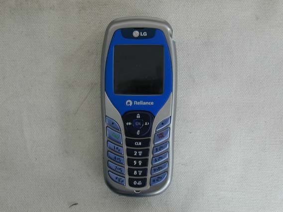
Click to zoom
Application Details
- Equipment Class
- TNE - Licensed Non-Broadcast Transmitter Held to Ear
- Date of Grant
- Oct 27, 2004
- Application Purpose
- Original Equipment
- Date of Application
- Oct 27, 2004
- Equipment Note
- CDMA Cellphone
- Frequency Range
- 824.82000000 - 848.19000000
- Company
- LG Electronics USA, Inc.
- Country
- United States
Documents & Files
Document Text
Text extracted from the exhibit documents filed with the FCC. Open a document above to read the original.
Users Manual
LG-RD5330 User Guide CDMA PHONE Contents Introduction Highlights Important Information Check Accessories Before You Start FCC RF EXPOSURE INFORMATION Chapter 1. Getting Started Cautions Phone Overview On screen Icons Chapter 2. Basic Functions Turning the Phone On and Off Making a Call Correcting Dialing Mistakes Receiving Calls Emergency Dialing Speed Dialing Phone Book Features Chapter 3. Menu Features General Guidelines to MENU Access and Settings Names Messages Call History Profiles Setting Planner System Chapter 4. Book Features Names Chapter 5. Message Features Write Message Inbox Outbox Voice Mail Archive Draft Templates Erase Messages Settings Chapter 6. Functions used during a call Scratch pad Mute Voice Privacy Send my number Short DTMF Chapter 7. Accessories Appendix 1. Installation Appendix 2. Consumer Information on SAR RF Exposure Information WARNING! Read this information before operating the phone. In August 1996, the Federal Communications (FCC) of the United States, with its action in Report and Order FCC 96-326, adopted an updated safety standard for human exposure to radio frequency(RF) electromagnetic energy emitted by FCC regulated transmitters. Those guidelines are consistent with the safety standard previously set by both U.S. and international standards bodies. The design of this phone complies with the FCC guidelines and these international standards. Body Worn Operation This device was tested for typical body-worn operations with the back of the phone kept 1.5 cm from the body. To comply with FCC RF exposure requirements, a minimum separation distance of 1.5 cm must be maintained between the user’s body and the back of the phone, including the antenna, whether extended or retracted. Third-party belt-clips, holsters, and similar accessories containing metallic components should not be used. Avoid the use of accessories that cannot maintain 1.5 cm distance between the user’s body and the back of the phone and have not been tested for compliance with FCC RF exposure limits. CAUTION Use only the supplied and approved antenna. Use of unauthorized antennas or modifications could impair call quality, damage the phone, void your warranty and/or result in violation of FCC regulations. Do not use the phone with a damaged antenna. If a damaged antenna comes into contact with skin, a minor burn may result. Contact your local dealer for a replacement of antenna. For Your Safety FCC Part 15 Class B Compliance This device and its accessories comply with part 15 of FCC rules. Operation is subject to the following two conditions: (1) This device and its accessories may not cause harmful interference, and (2) this device and its accessories must accept any interference received, including interference that may cause undesired operation. Chapter 1. Getting Started Cautions z Using the phone in proximity to receiving equipment (i.e., TV or radio) may cause interference. z Keep your phone in a safe place when not in use. z Only use the batteries, antennas, and chargers provided by LG. Using the wrong accessories could void your warranty. z Only authorized personnel should service the phone and its accessories. Faulty installation or service may result in accidents and consequently invalidate the warranty. z Do not hold the antenna while the phone is in use. z Do not use the phone in designated “no cellular phone use” areas. z Do not expose the phone to high temperature or humidity. z Avoid getting your phone wet. If the phone gets wet, turn the power off immediately and remove the battery pack. If the phone is mal-functional, return it to the dealer for service. z Avoid shock or impact on the phone. Phone Overview Function Key Descriptions Lamp The light goes on when you use the power key to turn on the phone and when there are incoming calls and messages. LCD screen Displays messages & indicator icons. END/PWR Used to turn power on/off. This key disconnects a call. Using this key, you can also exit out of a menu back to the phone’s standby display without changing the setting. SEND Allows user to place or answer calls. Mouse Key This mouse key allows quick access to text and voice mail notification messages. Profiles, R- World, and RingTone menu. And these keys are used to scroll through the memory locations and menu items. Alphanumeric Keypad These keys enable you to enter numbers and characters and choose menu items. Soft Keys The current operation of a soft key is defined by the word at the bottom of the display. Soft Keys 2 : If you press this key once in a menu, you can go back one level and if you press and hold the key in a menu, you can go back to the standby display. OK Key This key enables you to choose one item in the menu list. If you press this key in idle, mobile will show you the ‘My menu’ selection window. Star/Pound Key - In the standby status, set the manner mode by pressing the [ * ]button. (for 2 seconds) - In the standby status, set the lock function by pressing the [ # ]button. (for 2 seconds) Clear Key This key erase character and In the standby status, you can go MyMenu On screen Icons The phone screen displays several onscreen icons and onscreen icons appears when the phone is power on. Icons Descriptions Displays the strength of the signal received by the phone and current signal strength is indicated as the number of bars displayed on the screen. No service The phone is not receiving a system signal. In use A call is in progress. No icon indicates the phone is in standby mode. Digital indicator Digital service is available. Analog indicator Analog service is unavailable Indicates that a text message or voice mail has been received Roaming The phone is outside of its home service area. Charge level Indicates battery charge level. D Chapter 2. Basic Functions Turning the Phone On and Off Turning the Phone On 1. Install a charged battery pack or connect the phone to an external power source such as the cigarette lighter adapter or car kit. 2. Press [END/PWR…
Text truncated - open the document above for the full version.
Cover Letter(s)
American Telecommunications Certification Body Inc. 6731 Whittier Ave, McLean, VA 22101 October 20, 2004 RE: FCC ID: BEJRD5330_ATCB001825 Attention: Hyang Sook Yoon I have a few comments on this Application. Please note that further comments may arise in response to answers provided to the questions below. 1. Please provide the following information on the 731 form: Section III Item 2a - Technical Contact information, item 4a – Equipment code (PCE etc) and description of device, item 4b – Rule part for certification, Section IV item 1 – check the yes box for the anti-drug certification, item 2a – name of applicant or agent and title, item 2b,c,d,e – address, phone number, email of agent/applicant. 2. Please provide the tune up procedures for this device. 3. Please provide the operational description (theory of operation) for this device. 4. Please note that PCB layout drawings are not schematics. Please provide the schematics for this device. 5. Please provide the necessary SAR warning statements and SAR levels in the manual as required. 6. Please provide the sample equation used to determine the ERP of the fundamental. 7. Please note that the table for ERP of the fundamental located on page 7 of the report does not agree with your ERP procedure on page 5 of the report. It appears that all you have done is to add the conducted power measured with the power meter to some unspecified factor. This is not the proper method to determine ERP for part 22 devices. Please also note that the procedure states that you used an analyzer, but the data in the table states you used a power meter. Also, the table does not provide the substitution antenna factor or the cable factor. Please provide data in agreement with the accepted antenna substitution method (i.e. include substitution factor, cable factor and formula) and please be consistent in the equipment used. Also, for reference to the SAR report, you will need to leave the conducted power values in the report. 8. Please note that the test procedure on page 10 of the report does not agree with the field strength measurement method performed on page 11 or the report. Please note that the ERP of the spurious emissions is not a field strength measurement (i.e. it is not a measurement of field strength which is subsequently compared to a calculated field strength value), but is an antenna substitution measurement in accordance with TIA603. Please provide the proper antenna substitution method test data. Please show the formula used to account for the substitution antenna and the cable loss. 9. Please note that when measured SAR ERP or conducted power differs from EMC ERP or conducted powers, the SAR power must be the greater. Please note that the ERP in the EMC report is 25.72dBm. Also, please note that it appears that the EMC report indicates that conducted power from the table on page 7 of the EMC report and the conducted power in the SAR report (conducted power indicated on page 19 of the SAR report). The conducted power in the SAR report is 0.16dB less than that in the EMC report. Please remember that power in the SAR report (when there is a difference) must be the greater. Please provide SAR test data that clearly identifies the type of power measured and please test SAR with the same or greater measured power in comparison to the EMC report. 10. Please show/list the separation distances in the setup photos for body worn SAR testing. 11. Please note that the probe calibration lists an uncertainty of 11+%. The uncertainty budget in the SAR report lists the probe uncertainty as 4.8%. Please explain. 12. Please note that tissue verification needs to be done on each separate day of testing. The brain tissue verification is only shown for 10/4. However, head SAR testing was done on 10/7 and 10/6. This is two full days after the head tissue validation was performed. The body tissue verification is only shown for 10/6. However body SAR testing was performed on 10/8, 10/11 and 10/12. Also, the data provided in the files for brain tissue and muscle tissue are dated 10/14; again not the actual test dates. Please explain why the tissue verification for the actual tissue used in the testing has not been reported. Please provide the tissue validation data for the actual days tested. z Page 2 October 20, 2004 Dennis Ward mailto:[email protected] The items indicated above must be submitted before processing can continue on the above referenced application. Failure to provide the requested information may result in application termination. Correspondence should be considered part of the permanent submission and may be viewed from the Internet after a Grant of Equipment Authorization is issued. Please do not respond to this correspondence using the email reply button. In order for your response to be processed expeditiously, you must submit your documents through the AmericanTCB.com website. Also, please note that partial responses increase processing time and should not be submitted. Any questions about the content of this correspondence should be directed to the sender.
Cover Letter(s)
Oct 28. 2004 Federal Communication Commission Equipment Authorization Branch 7435 Oakland Mills Road Columbia, MID 21046 In re : LG Electronics Inc.. FCC ID: BEJRD5330 Single - Mode Cellular Phone (CDMA) Part 22 Certification Request for Confidentiality Gentlemen: In accordance with 0.459 of CFR 47, LG Electronics, Inc. hereby requests confidentiality of the Block Diagram, Schematic Diagrams, Operational Description, Technical Specification, Parts List, and Tune-Up Procedure for the above-referenced certification application. These documents contain detailed system and equipment description and related information about the product which LG Electronics Inc. Considers to be proprietary, confidential, and a custom design and, otherwise, would not release to the general public. Since this design is a basis from which future technological products will evolve, LG Electronics Inc. considers this information to be of benefit to its competitors, such that the disclosure of the information in these documents would give competitors an unfair advantage in the market. Sincerely, E.S.Park Chief Research Engineer CDMA Handset Lab LG Electronics Inc. Tel : 82- 2- 850-3850 Fax : 82- 2- 850-3855 [email protected] 459- 9, Kasan-dong,Kemchun-ku Seoul 153- 023, Korea LG Electronics Inc. LGE
Cover Letter(s)
Nov 1, 2004 Federal Communications Commission Authorization and Evaluation Div. Equipment Authorization Branch 7435 Oakland Mills Road Columbia, MD 21046 In re: LG Electronics Inc. FCC ID: BEJRD5330 Request for Short-Term Confidentiality To Whom It May Concern: In accordance with 0.457 and 0.459 of CFR 47, LG Electronics Inc. requests short-term confidentiality for the test setup photos, external photos, internal photos, and user’s manual of the attached test report. These documents contain detailed system and equipment descriptions and related information about the product, which LG Electronics Inc. considers to be proprietary, confidential, and a custom design and otherwise, would not release to the general public. Since this design is a basis from which future technological products will evolve, LG Electronics feels that this information would be of benefit to its competitors, and that the disclosure of the information in these documents would give our competitors an unfair advantage in the market. Sincerely, E.S.Park Chief Research Engineer LG Electronics Inc. LG Electronics Inc. LGE Tel : 82-2-850-3850 Fax : 82-2-850-3861 [email protected] 459-9, Kasan-dong, Kemchun-ku Seoul 153-023, Korea
RF Exposure Info
APPLICANT NAME & ADDRESS : DATA & LOCATION OF TESTING LG Electronics Inc. Dates of testing : 2004 09/24~10/25 Test Site : ESTECH Co., Ltd. Korea Test Device : Test report no :Number of page : Contact person :Responsible test Engineer : Applicant Type : FCC CLASSIFICATION : FCC Rule Part(s) Test results : -LG-RD5330, LG-SD5330, LG-ID5330 are same products -Only model name is different Date and Signatures : 2004-10-25 Report Prepared By : Engineer/ M.J.Song (Signature) Mana ger Engineer/ Jay Kim (Signature) Test report no : ESTSAR0410-001 FCC ID : BEJRD5330Web : www. estech. co. kr Page 1 of 22 Testing has been Carried out in Accordance with : The Tested device complies with the requirements in respect of all parameters subject to the test. The test results and statements relate only to the items tested. The test report shall not be reproduced recept in full, without written approval of the laboratory. IEEE P1528-200X Draft 6.4 Recommended Practice for Determining the Peak Spatial-Average Specific Absorption Rate(SAR) in the Human Body Due to Wireless Communications Device : Experimental Techniques Licensed Portable Transmitter held to ear (PCE) §2.1093; FCC/OET Bulletin 65 Supplement C (July 2001) M.J.SongCheol-Goo Lee Certification Models : LG-RD5330, LG-SD5330, LG-ID5330 FCC ID :BEJRD5330 TYPE : SINGLE BAND, SINGLE MODE CDMA MOBILE PHONE SAR Compliace Test Report ESTSAR0410-00122 459-9, Kasan-dong, Keumchun-ku, Seoul 153-023, Korea 1. SUMMARY FOR SAR TET REPORT -------------------------------------------------------------------- 3/22 1.1 Head Configuration ---------------------------------------------------------------------------------------- 3/22 1.2 Body Worn Configuration -------------------------------------------------------------------------------- 3/22 1.3 Measurement Uncertainty -------------------------------------------------------------------------------- 3/22 2. INTRODUCTION ---------------------------------------------------------------------------------------------- 4/22 3. DESCRIPTION OF THE DEVICE UNDER TEST ----------------------------------------------------- 5/22 3.1 Antenna Description -------------------------------------------------------------------------------------- 5/22 3.2 Device Description ---------------------------------------------------------------------------------------- 5/22 3.3 Battery Option ---------------------------------------------------------------------------------------------- 5/22 4. TEST CONDITIONS ----------------------------------------------------------------------------------------- 6/22 4.1 Ambient Conditions ---------------------------------------------------------------------------------------- 6/22 4.2 RF Characteristics of The Test Site -------------------------------------------------------------------- 6/22 4.3 Test Signal, Frequencies, And Output Power --------------------------------------------------------- 6/22 5. DESCRIPTION OF THE TEST EQUIPMENT ------------------------------------------------------------ 7/22 5.1 Test System Specifications ------------------------------------------------------------------------------ 7/22 5.2 SAR Measurement Setup --------------------------------------------------------------------------------- 7/22 5.3 DASY 4 E-Field Probe System ------------------------------------------------------------------------- 8/22 5.4 Phantom & Equivalent Tissues ------------------------------------------------------------------------ 10/22 6. DESCRIPTION OF THE TEST PROCEDURE ------------------------------------------------------- 12/22 6.1 Definition of Reference Point --------------------------------------------------------------------------- 12/22 6.2 Test Configuration Positions --------------------------------------------------------------------------- 13/22 6.3 Scan Procedures ----------------------------------------------------------------------------------------- 16/22 6.4 SAR Averaging Methods -------------------------------------------------------------------------------- 16/22 7. MEASUREMENT UNCERTAINTY ----------------------------------------------------------------------- 17/22 8. SYSTEM VERIFICATION ---------------------------------------------------------------------------------- 18/22 8.1 Tissue Verification --------------------------------------------------------------------------------------- 18/22 8.2 Test System Validation --------------------------------------------------------------------------------- 18/22 9. RESULTS ---------------------------------------------------------------------------------------------------- 19/22 10. REFERENCES -------------------------------------------------------------------------------------------- 22/22 APPENDIX A : Validation Test Data APPENDIX B : SAR Test Setup Photographs APPENDIX C : SAR Test Data APPENDIX D : Calibration Certificates Test report no : ESTSAR0410-001 FCC ID : BEJRD5330Web : www. estech. co. kr Page 2 of 22 Table of Contents Maximum Results Found During SAR Evaluation 1.1 Head Configuration Max. SAR Measurement MHz ChdBm Battery 848.19 772 CDMA 25 Standard Left Cheek Touch -1.06 1.2 Body Worn Configuration Max. SAR Measurement MHz ChdBm Battery 848.19 772 CDMA 25 Standard 1.5 [w/o Holster] -0.793 1.3 Measurement Uncertainty Test report no : ESTSAR0410-001 FCC ID : BEJRD5330Web : www. estech. co. kr Page 3 of 22 11.21 / 11.37 (k=1) 22.42 / 22.72 (k=2, 95% CONFIDENCE LEVEL) Combine Standard Uncertainty Extended Standard Uncertainty CDMA (25.00 dBm) SAR (W/kg) FREQUENCY FREQUENCY Modulation Power Separation test position Antenna position SAR (W/kg) Antenna position EUT Type Tx Frequency Device test position Modulation Power Rx Frequency Max. RF Output Power SINGLE BAND, SINGLE MODE CDMA MOBILE PHONE 824.820 ~ 848.190 MHz (CDMA) 869.820 ~ 893.190 MHz (CDMA) 1. SUMMARY FOR TEST REPORT Date of test FCC ID Measurement performed by 2004. 9. 24 - 2004. 10. 25 BEJRD5330 Jay Kim Responsible test engineer M.J.Song SAR Definition Figure 2.1 SAR Math…
Text truncated - open the document above for the full version.
RF Exposure Info
Title SubTitle October 21, 2004 03:39 PM 810. MHz860. MHz 40.70 40.50 40.30 40.10 39.90 39.70 e' < Memory 1 Title SubTitle October 21, 2004 03:39 PM 810. MHz860. MHz 19.160 19.120 19.080 19.040 19.000 18.960 e'' < Memory 1 Title SubTitle October 21, 2004 03:39 PM Frequency 810.000000 MHz 810.973262 MHz 811.946524 MHz 812.919785 MHz 813.893047 MHz 814.866309 MHz 815.845418 MHz 816.824527 MHz 817.803636 MHz 818.782745 MHz 819.761854 MHz 820.746845 MHz 821.731836 MHz 822.716828 MHz 823.701819 MHz 824.686810 MHz 825.677719 MHz 826.668628 MHz 827.659537 MHz 828.650446 MHz 829.641354 MHz 830.638216 MHz 831.635078 MHz 832.631941 MHz 833.628803 MHz 834.625665 MHz 835.628516 MHz 836.631367 MHz 837.634218 MHz 838.637068 MHz 839.639919 MHz 840.648795 MHz 841.657671 MHz 842.666547 MHz 843.675423 MHz 844.684299 MHz 845.699236 MHz 846.714173 MHz 847.729110 MHz 848.744047 MHz 849.758984 MHz 850.780018 MHz 851.801053 MHz 852.822087 MHz 853.843122 MHz 854.864157 MHz 855.891325 MHz 856.918494 MHz 857.945663 MHz 858.972831 MHz 860.000000 MHz e'e'' 40.547619.1219 40.546919.1183 40.513519.1126 40.520219.0963 40.510219.1380 40.474419.1223 40.485519.0833 40.480019.1021 40.463919.0811 40.433319.0853 40.420719.1166 40.406419.0632 40.408719.1114 40.357619.0785 40.396919.1062 40.371019.0878 40.369819.0838 40.316819.0831 40.355019.0685 40.287819.0928 40.303719.0736 40.294419.0400 40.293919.0777 40.235819.0574 40.262019.0772 40.233419.0490 40.205319.0624 40.205719.0262 40.205119.0634 40.186119.0326 40.190019.0477 40.137219.0468 40.121619.0669 40.143819.0352 40.072919.0237 40.101619.0162 40.062219.0064 40.057419.0286 40.042619.0328 40.051019.0461 40.037518.9983 39.998619.0089 39.995418.9994 39.977119.0095 39.958819.0196 39.944919.0080 39.923819.0084 39.945118.9767 39.913019.0109 39.915218.9844 39.897018.9943
RF Exposure Info
Title SubTitle October 22, 2004 03:42 PM 810. MHz860. MHz 41.50 41.30 41.10 40.90 40.70 40.50 e' < Memory 1 Title SubTitle October 22, 2004 03:42 PM 810. MHz860. MHz 19.230 19.190 19.150 19.110 19.070 19.030 e'' < Memory 1 Title SubTitle October 22, 2004 03:42 PM Frequency 810.000000 MHz 810.973262 MHz 811.946524 MHz 812.919785 MHz 813.893047 MHz 814.866309 MHz 815.845418 MHz 816.824527 MHz 817.803636 MHz 818.782745 MHz 819.761854 MHz 820.746845 MHz 821.731836 MHz 822.716828 MHz 823.701819 MHz 824.686810 MHz 825.677719 MHz 826.668628 MHz 827.659537 MHz 828.650446 MHz 829.641354 MHz 830.638216 MHz 831.635078 MHz 832.631941 MHz 833.628803 MHz 834.625665 MHz 835.628516 MHz 836.631367 MHz 837.634218 MHz 838.637068 MHz 839.639919 MHz 840.648795 MHz 841.657671 MHz 842.666547 MHz 843.675423 MHz 844.684299 MHz 845.699236 MHz 846.714173 MHz 847.729110 MHz 848.744047 MHz 849.758984 MHz 850.780018 MHz 851.801053 MHz 852.822087 MHz 853.843122 MHz 854.864157 MHz 855.891325 MHz 856.918494 MHz 857.945663 MHz 858.972831 MHz 860.000000 MHz e'e'' 41.248319.1711 41.220819.1947 41.228119.1875 41.225319.1829 41.182719.1892 41.212719.1865 41.177419.1801 41.147719.1936 41.152419.1764 41.135419.1971 41.142819.1898 41.107819.1834 41.108119.1888 41.101219.2067 41.062019.2227 41.096419.1975 41.025119.2117 41.049619.1892 41.020619.2025 40.979119.2087 40.975919.1622 40.962319.1924 40.935219.1736 40.952619.1637 40.921319.1672 40.894419.1485 40.944819.1819 40.879019.1740 40.864619.1623 40.873419.1966 40.826419.1419 40.851919.1610 40.796319.1505 40.805819.1116 40.773519.1467 40.761619.1242 40.739219.1202 40.744519.1034 40.731119.1125 40.723919.1250 40.702019.0848 40.689319.1144 40.667519.0743 40.702619.0904 40.643819.1019 40.650719.0539 40.647819.0807 40.609819.0556 40.613719.0701 40.590719.0615 40.584019.0380
RF Exposure Info
Title SubTitle October 23, 2004 03:45 PM 810. MHz860. MHz 53.10 52.90 52.70 52.50 52.30 52.10 e' < Memory 1 Title SubTitle October 23, 2004 03:45 PM 810. MHz860. MHz 20.420 20.380 20.340 20.300 20.260 20.220 e'' < Memory 1 Title SubTitle October 23, 2004 03:45 PM Frequency 810.000000 MHz 810.973262 MHz 811.946524 MHz 812.919785 MHz 813.893047 MHz 814.866309 MHz 815.845418 MHz 816.824527 MHz 817.803636 MHz 818.782745 MHz 819.761854 MHz 820.746845 MHz 821.731836 MHz 822.716828 MHz 823.701819 MHz 824.686810 MHz 825.677719 MHz 826.668628 MHz 827.659537 MHz 828.650446 MHz 829.641354 MHz 830.638216 MHz 831.635078 MHz 832.631941 MHz 833.628803 MHz 834.625665 MHz 835.628516 MHz 836.631367 MHz 837.634218 MHz 838.637068 MHz 839.639919 MHz 840.648795 MHz 841.657671 MHz 842.666547 MHz 843.675423 MHz 844.684299 MHz 845.699236 MHz 846.714173 MHz 847.729110 MHz 848.744047 MHz 849.758984 MHz 850.780018 MHz 851.801053 MHz 852.822087 MHz 853.843122 MHz 854.864157 MHz 855.891325 MHz 856.918494 MHz 857.945663 MHz 858.972831 MHz 860.000000 MHz e'e'' 52.931320.4136 52.885820.3814 52.871220.4054 52.856220.3961 52.871520.4096 52.846720.4038 52.808520.3915 52.823920.4049 52.815520.3822 52.834420.4055 52.773320.3903 52.781820.3839 52.744620.4047 52.736420.3821 52.712720.4091 52.685020.3935 52.697120.3968 52.679920.4105 52.646120.4081 52.673720.3619 52.598220.3964 52.589720.3412 52.605420.3542 52.553120.3914 52.580820.3453 52.584120.3846 52.547320.3725 52.543120.3597 52.510720.3898 52.502420.3349 52.521820.3573 52.453020.3461 52.506720.3126 52.481520.3618 52.450720.3045 52.487220.2989 52.410820.3556 52.391120.2837 52.423620.3119 52.394620.3191 52.412520.2769 52.422520.3024 52.377320.2939 52.383020.2778 52.344820.2884 52.347220.2628 52.350520.2690 52.334920.2822 52.349320.2308 52.318320.2603 52.295020.2228
Test Report
Report Number: ESTR0410-008 Dates: October 14, 2004 Page 1 of 21 FCC ID: BEJRD5330 EUT Type: Single Band, Single Mode CDMA Mobile Phone Test Report Report Number ESTR0410-008 Company Name LG Electronics Inc. Address 459-9, Kasan-dong, Keumchun-ku, Seoul 153-023, Korea Applicant Telephone 82-2-850-3860 Product Name Single Band, Single Mode CDMA Mobile Phone Model No. LG-RD5330,LG- SD5330,LG-ID5330 Manufacturer LG Electronics Inc. Serial No. NONE Country of origin Korea Product Date of Issue 2004-10-14 Date of Test 2004-09-24 ~2004-10-13 Testing Lab. ESTECH. Co., Ltd Standard FCC PART 22 Subpart H Tested by S.R. Kim/ Engineer (Signature) Approved by Jay Kim/ Manager Engineer (Signature) * Note - This test report is not permitted to copy partly without our permission - This test result is dependent on only equipment to be used - This test result based on a single evaluation of one sample of the above mentioned Report Number: ESTR0410-008 Dates: October 14, 2004 Page 2 of 21 FCC ID: BEJRD5330 EUT Type: Single Band, Single Mode CDMA Mobile Phone TABLE OF CONTENTS ATTACHMENT: TEST RESULT CERTIFICATION............................ 1 1. INTRODUCTION.....................................................................3 2. DESCRIPTION OF EUT............................................................. 4 3. DESCRIPTION OF TEST.......................................................... .. 5 4. TEST DATA 4.1 EFFECTIVE RADIATED POWER OUTPUT (E.R.P.).......................7 4.2 OCCUPIED BANDWIDTH ................................................9 4.3 FIELD STRENGTH OF SPURIOUS RADIATION .....................11 4.4 SPURIOUS EMISSION AT ANTENNA TERMINAL................... 14 4.5 FREQUENCY STABILITY................................................... 16 5. TEST PLOTS 5.1 PLOTS OF EMISSIONS........................................................17 5.1.1 PLOTS OF EMISSION (CDMA): BAND EDGE.......................................19 5.1.2 PLOTS OF EMISSION (CDMA): OUT OF BAND....................................20 5.2 MOBILE EMISSION IN BASE FREQUENCY RANGE................21 Report Number: ESTR0410-008 Dates: October 14, 2004 Page 3 of 21 FCC ID: BEJRD5330 EUT Type: Single Band, Single Mode CDMA Mobile Phone 1. INSTROCTION 1.1 General This EUT (Equipment Under Test) has been shown to be capable of compliance with the applicable technical standards and tested in accordance with the measurement procedures as indicated in this report ESTECH Lab attests to accuracy of test data. All measurement reported herein were performed by ESTECH Co., Ltd. ESTECH Lab., assume full responsibility for the completeness of these measurements and vouch for the qualifications of all persons taking them. 1.2 Test Lab. Corporation Name: ESTECH Co. Ltd. Head Office: 3 rd Fl., Chungdam Bldg., 119-1, Chungdam-dong Kangnam-gu , Seoul, Korea (Safety & Telecom. Test Lab) EMC Test Lab.: 58-1, Osan-Ri, GaNam-Myon, YeoJoo-Gun, KyungKi-Do, Korea 97-1, Hoiuk-Ri Majang-Myon, Icheon-city, KyungKi-Do, Korea Report Number: ESTR0410-008 Dates: October 14, 2004 Page 4 of 21 FCC ID: BEJRD5330 EUT Type: Single Band, Single Mode CDMA Mobile Phone 2. Description of EUT 2.1 Summary of Equipment Under Test ♦ FCC ID : BEJRD5330 ♦ Freq. Range : Tx : 824.820 ~ 848.190 MHz Rx : 869.820 ~ 893.190 MHz ♦ Power Rating : 3.7VDC(3.2 ~ 4.2VDC) ♦ EUT Type : Single Band, Single Mode CDMA Mobile Phone ♦ Modulation(s) : CDMA - FM . Report Number: ESTR0410-008 Dates: October 14, 2004 Page 5 of 21 FCC ID: BEJRD5330 EUT Type: Single Band, Single Mode CDMA Mobile Phone 3. DESCRIPTION OF TEST 3.1 RF Power Output - The EUT was placed on a wooden turn table 3 meters from the receive antenna. The receive antenna height and turn table rotation was adjusted for the highest reading on the receive spectrum analyzer. For CDMA signals, a peak detector is used, with RBW = VBW = 3MHz. For AMPS, GSM, and NADC TDMA signals, a peak detector is used, with RBW = VBW = 1MHz, A Horn antenna was substituted in place of the EUT. This Horn antenna was driven by a signal generator and the level of the signal generator was adjusted to obtain the same receive spectrum analyzer reading. This spurious level is recorded. For reading 1GHz, the above procedure is repeated using horn antennas and the difference between the gain of the horn and an isotropic or dipole antenna are taken into consideration. 3.5 Occupied Bandwidth The transmitter output is connected to the spectrum analyzer. The RBW is set to 1% of the Emission bandwidth. The VBW is set to 3 times the RBW. The sweep time is coupled. 3.6 Spurious and Harmonic Emission at Antenna Terminal The level of the carrier and the various conducted spurious and harmonic frequencies is measured by means of a calibrated spectrum analyzer. The spectrum is scanned from the lowest frequency generated in the equipment up to 10GHz. Set the RES BW to 1% of the emission bandwidth to show compliance with the -13dBm, limit, in the 1MHz bands immediately outside and adja…
Text truncated - open the document above for the full version.
Contact Information
Applicant
David Kim(Team leader, LGEUS NA Policy & Regulatory Affairs)
Technical Contact
LG Electronics Inc.Cheol-Goo Lee
[email protected]82-2-850-3860
459-9, Kasan-dong, Keumchun-ku · Seoul · South Korea
Technical Specifications
| # | Rule Parts | Frequency Range | Power Output | Emission | Tolerance |
|---|---|---|---|---|---|
| 1 | 22H | 824.82 MHz - 848.19 MHz | 289.00 mW | 1M25F9W | 42.0000000000 Hz |
Other Applications from LG Electronics USA, Inc.

BEJTFHOBINI1F1
Jan 08, 2025Telematics
Equipment Class
DTS - Digital Transmission SystemBEJNT-16Z90TS
Oct 02, 2024Notebook Computer
Equipment Class
DSS - Part 15 Spread Spectrum TransmitterBEJSP-PEW8
Sep 26, 2024Stylus Pen
Equipment Class
DCD - Part 15 Low Power Transmitter Below 1705 kHzBEJ-RSMV2
Sep 24, 2024RF Module
Equipment Class
FDS - Part 15 Field Disturbance SensorBEJTFBMEIBN3EU
Sep 24, 2024Telematics
Equipment Class
NII - Unlicensed National Information Infrastructure TX