BEJRU42PX2042-inch Plasma Monitor
LG Electronics USA, Inc.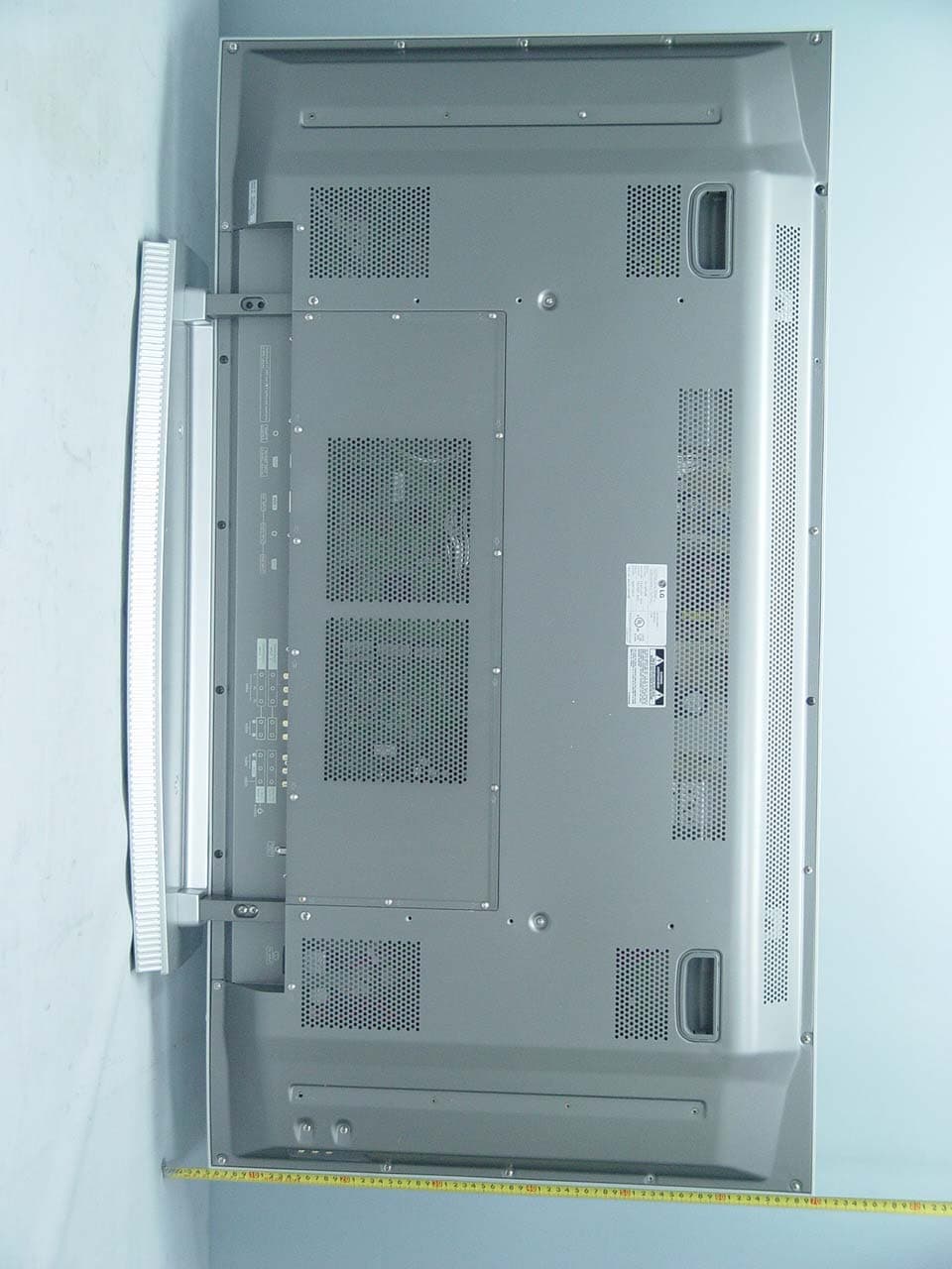
Click to zoom
Application Details
- Equipment Class
- JBP - Part 15 Class B Computing Device Peripheral
- Date of Grant
- Apr 07, 2004
- Application Purpose
- Original Equipment
- Date of Application
- Apr 07, 2004
- Equipment Note
- 42-inch Plasma Monitor
- Company
- LG Electronics USA, Inc.
- Country
- United States
Documents & Files
Document Text
Text extracted from the exhibit documents filed with the FCC. Open a document above to read the original.
Users Manual
1 Plasma TV Warning WARNING: TO REDUCE THE RISK OF ELECTRIC SHOCK DO NOT REMOVE COVER (OR BACK). NO USER SERVICEABLE PARTS INSIDE. REFER TO QUALIFIED SERVICE PERSONNEL. The lightning flash with arrowhead symbol, within an equilateral triangle, is intended to alert the user to the presence of uninsulated “dangerous voltage” within the product’s enclosure that may be of suffi- cient magnitude to constitute a risk of electric shock to persons. The exclamation point within an equilateral triangle is intended to alert the user to the presence of important operating and maintenance (servicing) instructions in the literature accompanying the appli- ance. WARNING: TO PREVENT FIRE OR SHOCK HAZARDS, DO NOT EXPOSE THIS PRODUCT TO RAIN OR MOISTURE. NOTE TO CABLE/TV INSTALLER: This reminder is provided to call the CATV system installer’s attention to Article 820-40 of the National Electric Code (U.S.A.). The code provides guidelines for proper grounding and, in particular, specifies that the cable ground shall be connected to the grounding system of the building, as close to the point of the cable entry as prac- tical. REGULATORY INFORMATION This equipment has been tested and found to comply with the limits for a Class B digital device, pursuant to Part 15 of the FCC Rules. These limits are designed to provide reasonable protection against harmful interference in a residential installation. This equipment generates, uses and can radiate radio frequency energy and, if not installed and used in accordance with the instructions, may cause harmful interference to radio communications. However, there is no guarantee that interference will not occur in a particular installation. If this equipment does cause harmful interference to radio or television reception, which can be determined by turning the equipment off and on, the user is encouraged to try to correct the interference by one or more of the following measures: - Reorient or relocate the receiving antenna. - Increase the separation between the equipment and receiver. - Connect the equipment into an outlet on a circuit different from that to which the receiver is connected. - Consult the dealer or an experienced radio/TV technician for help. Any changes or modifications not expressly approved by the party responsible for compliance could void the user’s authority to operate the equipment. CAUTION: Do not attempt to modify this product in any way without written authorization. Unauthorized modification could void the user’s authority to operate this product. CAUTION RISK OF ELECTRIC SHOCK DO NOT OPEN W W arning arning 2 Plasma TV Warning Safety Instructions Safety Instructions 1. Do not place the product in direct sunlight or near heat sources such as heat registers, stove and so on. This may cause a fire. 2. Do not use the product in damp place such as a bathroom or any place where it is likely to get wet. This may cause a fire or could give an electric shock. 3. Bend antenna cable between inside and outside building to prevent rain from flowing in. This may cause water damaged inside the product and could give an electric shock. 4. Earth wire should be connected. - If the earth wire is not connected, there is possible a danger of electric shock caused by the current leakage. - If grounding methods are not possible, a separate circuit breaker should be employed and installed by a qualified electrician. - Do not connect ground to telephone wires, lightning rods or gas pipe. 5. Do not placing anything containing liquid on top of the product. This may cause a fire or could give an electric shock. 6. Do not insert any object into the exhaust vent. This may cause a fire or could give an electric shock. 7. Do not place heavy objects on the product. This may cause serious injury to a child or adult. 8. Do not use water the product while cleaning. This may cause damaged the product or could give an elec- tric shock. 9. In case of smoke or strange smell from the prod- uct, switch it off ,unplug it from the wall outlet and contact your dealer or service center. This may cause a fire or could give an electric shock. 10. Do not attempt to service the product yourself. Contact your dealer or service center. This may cause damaged the product or could give an elec- tric shock. 11.During a lightning thunder, unplug the product from the wall outlet and don’t touch an antenna cable. This may cause damaged the product or could give an elec- tric shock. W WARNING * Safety instructions have two kinds of information, and each meaning of it is as below. Take care of danger that may happen under specific condition. The violation of this instruction may cause serious injuries and even death. The violation of this instruction may cause light injuries or damage of the product. WARNING NOTES Power supplier Short-circuit breaker Owner’s Manual 3 Safety Instructions 1. Never touch the power plug with a wet hand. This may cause an electric shock. 2. Disconnect from the mains and remove all con- nections before moving. 3. Do not place the product in a built-in installation such as a bookcase or rack. Ventilation required. 4. When installing the product on a table, be careful not to place the edge of its stand. This may cause the product to fall, causing serious injury to a child or adult, and serious damage to the product. 5. Do not place an outside antenna in the vicinity of overhead power lines or other electric light or power circuits. This may cause an electric shock. 6. There should be enough distance between an out- side antenna and power lines to keep the former from touching the latter even when the antenna falls. This may cause an electric shock. 7. Do not pull the cord but the plug when unplug- ging. This may cause a fire. 8. Ensure the power cord doesn’t trail across any hot objects like a heater. This may cause a fire or an electric shock. 9. Do not plug when the power cord or the plug is damaged or the connecting part of the power out- let is loose. This may cause a …
Text truncated - open the document above for the full version.
Attestation Statements
May 01, 2003 Federal Communications Commission Authorization and Evaluation Division Equipment Authorization Branch 7435 Oakland Mills Road Columbia, MD 21046 U.S.A To whom it may concern: We, the undersigned, hereby authorize GUMI College EMC Center to act on our behalf in all matters relating to applications for equipment authorization, including the signing of all documents relation to these matters. Any and all acts carried out by GUMI College EMC Center on our behalf shall have the same effect as acts of our own. We also hereby certify that no party to the application is subject of a denial of benefits, including FCC benefits, pursuant 5301 of the Anti-Drug Abuse Act of 1988, 21 U.S.C. 853(a). Sincerely, Woo-Hyun Oh, Group Leader LG Electronics Inc. TV Plant
Block Diagram
RGB (PC/DTV) DVI (PC/DTV) RS232 IR 74ACT253 RX0/1,TX0/1 IR TX SCL/SDA RGB H/V SCL/SDA RX/TX0/1/2 ± , RX/TXC ± ST3232C 24LC21 74HCT08 24LC21 CXA2101 Scart1Scart2Scart3 RF Comp1 (DVD/DTV) CVBSS-VHS CXA2069Q SWITCH Tuner (M) Tuner(S) Vin1 (CVBS) VPC3230 (M) Video Decoder VPC3230 (S) Video Decoder 1H RGB Vin2 (CVBS) MNT OUT TV OUT Vin3 (CVBS) TU_Main TU_Sub Vin4YCin4 Main_V Main_YC Main_V Main_YC SDA6001 Text Processor Text_V HYV641620 SRAM AM29LV160 F-ROM 74LS123 Comp_480i M52758F Switch S2300 DeInterlacer YCbCr /8 HY57V64322 SDRAM (8MB) RGB PC/DTV RGB PC RGB DTV gm1601 Scaler (Malibu) Comp DTV CXA_RGB RGB_Data Main_Video / 24 Sub_Video /8 DVI_Data TX_Out RS232_RX/TX Comp/RGB_SW From Malibu Digital B’D Analog B’D Side-AV B’D CVBS S-VHS Vin5 YCin5 Comp_Y Comp_480I/P To Malibu Video for Text Text LVDS_31P TX0/1/2/3/C ± Disp_EnSDATASCLK, SLE HY5DU283222A SDRAM (128MB) AM29LV F-ROM (1MB) Comp /RGB_SW Comp_480I/P ※ Post-processing Block is omitted. so-called JEPICO, in this caseTMDS TX is also required. ※ Sound Processing Block Diagram is separated.. ※ RCA-type Block Diagram is also separated.. X10Series Scart-type Block Diagram X10Series Scart-type Block Diagram DVI RX w/HDCP ADC w/PLL IEP ZHINE 24 24 10 Crystal 20.25MHz 5V Crystal 6MHz 5V Crystal 13.5MHz 5V Crystal 14.31818MHz 5V Crystal 20.25MHz 5V MSP 4410G Crystal 18.432MHz 5V
External Photos
EUT Type: 42” Plasma Monitor FCC ID : BEJRU42PX20 Test Report No.: GETEC-E3-04-013 FCC Class B Certification EUT Type: 42” Plasma Monitor FCC ID : BEJRU42PX20 Test Report No.: GETEC-E3-04-013 FCC Class B Certification EUT Type: 42” Plasma Monitor FCC ID : BEJRU42PX20 Test Report No.: GETEC-E3-04-013 FCC Class B Certification EUT Type: 42” Plasma Monitor FCC ID : BEJRU42PX20 Test Report No.: GETEC-E3-04-013 FCC Class B Certification EUT Type: 42” Plasma Monitor FCC ID : BEJRU42PX20 Test Report No.: GETEC-E3-04-013 FCC Class B Certification EUT Type: 42” Plasma Monitor FCC ID : BEJRU42PX20 Test Report No.: GETEC-E3-04-013 FCC Class B Certification EUT Type: 42” Plasma Monitor FCC ID : BEJRU42PX20 Test Report No.: GETEC-E3-04-013 FCC Class B Certification
ID Label/Location Info
EUT Type: 42” Plasma Monitor FCC ID : BEJRU42PX20 Test Report No.: GETEC-E3-04-013 FCC Class B Certification LABELLING REQUIREMENTS The label shown shall be permanently affixed at a conspicuous location on the device and be readily visible to the user at the time of purchase. ID Label ID Label Location of EUT I.D Label
Internal Photos
EUT Type: 42” Plasma Monitor FCC ID : BEJRU42PX20 Test Report No.: GETEC-E3-04-013 FCC Class B Certification EUT Type: 42” Plasma Monitor FCC ID : BEJRU42PX20 Test Report No.: GETEC-E3-04-013 FCC Class B Certification EUT Type: 42” Plasma Monitor FCC ID : BEJRU42PX20 Test Report No.: GETEC-E3-04-013 FCC Class B Certification EUT Type: 42” Plasma Monitor FCC ID : BEJRU42PX20 Test Report No.: GETEC-E3-04-013 FCC Class B Certification EUT Type: 42” Plasma Monitor FCC ID : BEJRU42PX20 Test Report No.: GETEC-E3-04-013 FCC Class B Certification EUT Type: 42” Plasma Monitor FCC ID : BEJRU42PX20 Test Report No.: GETEC-E3-04-013 FCC Class B Certification EUT Type: 42” Plasma Monitor FCC ID : BEJRU42PX20 Test Report No.: GETEC-E3-04-013 FCC Class B Certification EUT Type: 42” Plasma Monitor FCC ID : BEJRU42PX20 Test Report No.: GETEC-E3-04-013 FCC Class B Certification EUT Type: 42” Plasma Monitor FCC ID : BEJRU42PX20 Test Report No.: GETEC-E3-04-013 FCC Class B Certification EUT Type: 42” Plasma Monitor FCC ID : BEJRU42PX20 Test Report No.: GETEC-E3-04-013 FCC Class B Certification EUT Type: 42” Plasma Monitor FCC ID : BEJRU42PX20 Test Report No.: GETEC-E3-04-013 FCC Class B Certification EUT Type: 42” Plasma Monitor FCC ID : BEJRU42PX20 Test Report No.: GETEC-E3-04-013 FCC Class B Certification EUT Type: 42” Plasma Monitor FCC ID : BEJRU42PX20 Test Report No.: GETEC-E3-04-013 FCC Class B Certification EUT Type: 42” Plasma Monitor FCC ID : BEJRU42PX20 Test Report No.: GETEC-E3-04-013 FCC Class B Certification EUT Type: 42” Plasma Monitor FCC ID : BEJRU42PX20 Test Report No.: GETEC-E3-04-013 FCC Class B Certification EUT Type: 42” Plasma Monitor FCC ID : BEJRU42PX20 Test Report No.: GETEC-E3-04-013 FCC Class B Certification EUT Type: 42” Plasma Monitor FCC ID : BEJRU42PX20 Test Report No.: GETEC-E3-04-013 FCC Class B Certification EUT Type: 42” Plasma Monitor FCC ID : BEJRU42PX20 Test Report No.: GETEC-E3-04-013 FCC Class B Certification EUT Type: 42” Plasma Monitor FCC ID : BEJRU42PX20 Test Report No.: GETEC-E3-04-013 FCC Class B Certification EUT Type: 42” Plasma Monitor FCC ID : BEJRU42PX20 Test Report No.: GETEC-E3-04-013 FCC Class B Certification EUT Type: 42” Plasma Monitor FCC ID : BEJRU42PX20 Test Report No.: GETEC-E3-04-013 FCC Class B Certification EUT Type: 42” Plasma Monitor FCC ID : BEJRU42PX20 Test Report No.: GETEC-E3-04-013 FCC Class B Certification EUT Type: 42” Plasma Monitor FCC ID : BEJRU42PX20 Test Report No.: GETEC-E3-04-013 FCC Class B Certification EUT Type: 42” Plasma Monitor FCC ID : BEJRU42PX20 Test Report No.: GETEC-E3-04-013 FCC Class B Certification EUT Type: 42” Plasma Monitor FCC ID : BEJRU42PX20 Test Report No.: GETEC-E3-04-013 FCC Class B Certification
Test Report
EUT Type: 42” Plasma Monitor FCC ID : BEJRU42PX20 Page 2 of 19 Test Report No.: GETEC-E3-04-013 FCC Class B Certification CONTENTS 1. SCOPE...........................................................................................................................................................................3 2. INTRODUCTION ........................................................................................................................................................4 3. TEST CONDITIONS & EUT INFORMATION........................................................................................................5 3.1 DESCRIPTION OF EUT..............................................................................................................................................5 3.2 SUPPORT EQUIPMENT USED.....................................................................................................................................6 4. DESCRIPTION OF TESTS.........................................................................................................................................7 4.1 CONDUCTED EMISSION............................................................................................................................................7 4.2 RADIATED EMISSIONS..............................................................................................................................................8 5. CONDUCTED EMISSION..........................................................................................................................................9 5.1 OPERATING ENVIRONMENT.....................................................................................................................................9 5.2 TEST SET-UP..............................................................................................................................................................9 5.3 MEASUREMENT UNCERTAINTY................................................................................................................................9 5.4 LIMIT......................................................................................................................................................................10 5.5 TEST EQUIPMENT USED..........................................................................................................................................10 5.6 TEST DATA FOR POWER LINE CONDUCTED EMISSION............................................................................................ 11 6. RADIATED EMISSION ............................................................................................................................................14 6.1 OPERATING ENVIRONMENT...................................................................................................................................14 6.2 TEST SET-UP............................................................................................................................................................14 6.3 MEASUREMENT UNCERTAINTY..............................................................................................................................14 6.4 LIMIT......................................................................................................................................................................15 6.5 TEST EQUIPMENT USED..........................................................................................................................................15 6.6 TEST DATA FOR RADIATED EMISSION.....................................................................................................................16 7. SAMPLE CALCULATIONS.....................................................................................................................................18 7.1 EXAMPLE 1 :...........................................................................................................................................................18 7.2 EXAMPLE 2 :...........................................................................................................................................................18 8. RECOMMENDATION & CONCLUSION..............................................................................................................19 APPENDIX A – ATTESTATION STATEMENT APPENDIX B – PLOTS OF CONDUCTED EMISSIONS APPENDIX C – ID SAMPLE LABEL & LOCATION APPENDIX D – BLOCK DIAGRAM APPENDIX E – TEST SET-UP PHOTOGRAPHS APPENDIX F – EXTERNAL PHOTOGRAPHS APPENDIX G –INTERNAL PHOTOGRAPHS APPENDIX H – USER’S MANUAL EUT Type: 42” Plasma Monitor FCC ID : BEJRU42PX20 Page 3 of 19 Test Report No.: GETEC-E3-04-013 FCC Class B Certification 1. Scope Measurement and determination of electromagnetic emissions (EME) of radio frequency devices including intentional and / or unintentional radiators for compliance with technical rules and regulations of the Federal Communications Commission . z FCC ID BEJRU42PX20 z EUT Type 42” Plasma Monitor z Model No. RU-42PX 10, RU-42PX20 (LG) P42W46X (Zenith) z Tra de Na me LG, Zenith z Rule Part(s) FCC Part 15 Subpart B z Test Procedure(s) ANSI C63.4 (1992) z Standard(s) EN55022:1998 (CISPR22:1997) z Dates of Test MARCH 29 ~ 30 z Place of Test Gumi College EMC Center z Test Report No. GETEC-E3-04-013 Responsible Party: LG Electronics Inc. Contact Person: Mr. Woo-Hyun Oh, Chief research engineer P P r r o o d d u u c c t t T T e e s s t t i i n n g g & & C C o o m m p p l l i i a a n n c c e e C C e e n n t t e e r r Manufacturer: 642, Jinpyoung-dong, Gumi-city, Gyeongsangbuk-do, Korea Tel No.: +82-54-470-4530 EUT Type: 42” Plasma Monitor FCC ID : BEJRU42PX20 Page 4 of 19 Test Report No.: GETEC-E3-04-013 FCC Class B Certification 2. Introduction The measurement procedure described in American National Standard for Methods of Measurement of Radio-Nose Emissions From Low-Voltage Electrical and Electronic Equipme…
Text truncated - open the document above for the full version.
Test Report
EUT Type: 42” Plasma Monitor FCC ID : BEJRU42PX20 Test Report No.: GETEC-E3-04-013 FCC Class B Certification Test Mode: 1280*1024 / 60Hz (Analog) < Hot line > < Neutral line > EUT Type: 42” Plasma Monitor FCC ID : BEJRU42PX20 Test Report No.: GETEC-E3-04-013 FCC Class B Certification Test Mode: 1024*768 / 85Hz (Digital) < Hot line > < Neutral line > EUT Type: 42” Plasma Monitor FCC ID : BEJRU42PX20 Test Report No.: GETEC-E3-04-013 FCC Class B Certification Test Mode: 1024*768 / 75Hz (Analog) < Hot line > < Neutral line > EUT Type: 42” Plasma Monitor FCC ID : BEJRU42PX20 Test Report No.: GETEC-E3-04-013 FCC Class B Certification Test Mode: 800*600 / 60Hz (Analog) < Hot line > < Neutral line > EUT Type: 42” Plasma Monitor FCC ID : BEJRU42PX20 Test Report No.: GETEC-E3-04-013 FCC Class B Certification Test Mode: 640*480 / 75Hz < Hot line > < Neutral line >
Test Setup Photos
EUT Type: 42” Plasma Monitor FCC ID : BEJRU42PX20 Test Report No.: GETEC-E3-04-013 FCC Class B Certification The Conducted Test Picture and Radiated Test Picture show the worst-case configuration and cable placement. Conducted Test Picture (Front) Conducted Test Picture (Rear) EUT Type: 42” Plasma Monitor FCC ID : BEJRU42PX20 Test Report No.: GETEC-E3-04-013 FCC Class B Certification Radiated Test Picture (Front) Radiated Test Picture (Rear)
Contact Information
Applicant
David Kim(Team leader, LGEUS NA Policy & Regulatory Affairs)
Technical Contact
PCTEST Engineering Lab., Inc.Randy Ortanez
[email protected]410-290-6652
6660-B Dobbin Road · Columbia, Maryland · United States
Test Firm
Gumi University EMC CenterTae-Sig Park
Technical Specifications
| # | Rule Parts | Frequency Range | Power Output |
|---|---|---|---|
| 1 | 15B | - | - |
Other Applications from LG Electronics USA, Inc.

BEJTFHOBINI1F1
Jan 08, 2025Telematics
Equipment Class
DTS - Digital Transmission SystemBEJNT-16Z90TS
Oct 02, 2024Notebook Computer
Equipment Class
DSS - Part 15 Spread Spectrum TransmitterBEJSP-PEW8
Sep 26, 2024Stylus Pen
Equipment Class
DCD - Part 15 Low Power Transmitter Below 1705 kHzBEJ-RSMV2
Sep 24, 2024RF Module
Equipment Class
FDS - Part 15 Field Disturbance SensorBEJTFBMEIBN3EU
Sep 24, 2024Telematics
Equipment Class
NII - Unlicensed National Information Infrastructure TX