BEJRU42PY10XPlasma Display Panel
LG Electronics USA, Inc.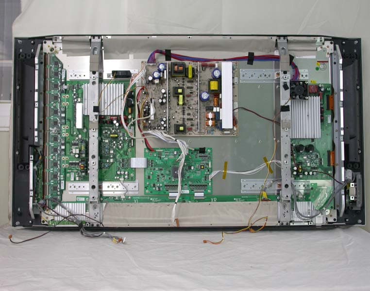
Click to zoom
Application Details
- Equipment Class
- JBP - Part 15 Class B Computing Device Peripheral
- Date of Grant
- May 07, 2005
- Application Purpose
- Original Equipment
- Date of Application
- May 07, 2005
- Equipment Note
- Plasma Display Panel
- Company
- LG Electronics USA, Inc.
- Country
- United States
Documents & Files
Document Text
Text extracted from the exhibit documents filed with the FCC. Open a document above to read the original.
Users Manual
PLASMA TV OWNER’S MANUAL Please read this manual carefully and completely before operating your TV. Retain this manual for future reference. Record model number and serial number of the TV in the spaces provided below. See the label attached on the back cover and relate this information to your dealer if you require service. Model Number : Serial Number : MODEL : 42PY1R-UA / RU-42PY10X LG Electronics U.S.A., Inc. 2 Plasma TV Warning/Caution WARNING/CAUTION: TO REDUCE THE RISK OF ELECTRIC SHOCK DO NOT REMOVE COVER (OR BACK). NO USER SERVICEABLE PARTS INSIDE. REFER TO QUALIFIED SERVICE PERSONNEL. The lightning flash with arrowhead symbol, within an equilateral triangle, is intended to alert the user to the presence of uninsulated “dangerous voltage” within the product’s enclosure that may be of suffi- cient magnitude to constitute a risk of electric shock to persons. The exclamation point within an equilateral triangle is intended to alert the user to the presence of important operating and maintenance (servicing) instructions in the literature accompanying the appli- ance. WARNING/CAUTION: TO PREVENT FIRE OR SHOCK HAZARDS, DO NOT EXPOSE THIS PRODUCT TO RAIN OR MOISTURE. FCC NOTICE • A Class B digital device This equipment has been tested and found to comply with the limits for a Class B digital device, pursuant to Part 15 of the FCC Rules. These limits are designed to provide reasonable protection against harmful interference in a residential installation. This equipment generates, uses and can radiate radio frequency energy and, if not installed and used in accordance with the instructions, may cause harmful interference to radio communications. However, there is no guarantee that interference will not occur in a particular installation. If this equipment does cause harmful interference to radio or television reception, which can be determined by turning the equipment off and on, the user is encouraged to try to correct the interference by one or more of the following measures: - Reorient or relocate the receiving antenna. - Increase the separation between the equipment and receiver. - Connect the equipment into an outlet on a circuit different from that to which the receiver is connected. - Consult the dealer or an experienced radio/TV technician for help. • Any changes or modifications not expressly approved by the party responsible for compli- ance could void the user’s authority to operate the equipment. CAUTION: Do not attempt to modify this product in any way without written authorization from LG Electronics. Unauthorized mod- ification could void the user’s authority to operate this product. COMPLIANCE: The responsible party for this product’s compliance is: LG Electronics U.S.A., Inc 1000 Sylvan Avenue, Englewood Cliffs, NJ 07632 1-800-243-0000 http://www.lgusa.com WARNING RISK OF ELECTRIC SHOCK DO NOT OPEN /CAUTION WARNING/CAUTION TO REDUCE THE RISK OF FIRE AND ELECTRIC SHOCK, DO NOT EXPOSE THIS PRODUCT TO RAIN OR MOISTURE. W W arning/Caution arning/Caution Owner’s Manual 3 Safety Instructions IMPORTANT SAFETY INSTRUCTIONS Important safety instructions shall be provided with each apparatus. This information shall be given in a separate booklet or sheet, or be located before any operating instructions in an instruction for installation for use and supplied with the appa- ratus. This information shall be given in a language acceptable to the country where the apparatus is intended to be used. The important safety instructions shall be entitled “Important Safety Instructions”. The following safety instructions shall be included where applicable, and, when used, shall be verbatim as follows. Additional safety information may be included by adding statements after the end of the following safety instruction list. At the manufacturer’s option, a picture or drawing that illustrates the intent of a specific safety instruction may be placed immediately adjacent to that safety instruction : 1. Read these instructions. 2. Keep these instructions. 3. Heed all warnings. 4. Follow all instructions. 5. Do not use this apparatus near water. 6. Clean only with dry cloth. 7. Do not block any ventilation openings. Install in accordance with the manufacturer’s instructions. 8. Do not install near any heat sources such as radiators, heat registers, stoves, or other apparatus (including ampli- fiers)that produce heat. 9. Do not defeat the safety purpose of the polarized or grounding-type plug. A polarized plug has two blades with one wider than the other. A grounding type plug has two blades and a third grounding prong, The wide blade or the third prong are provided for your safety. If the provided plug does not fit into your outlet, consult an electrician for replacement of the obsolete outlet. 10. Protect the power cord from being walked on or pinched particularly at plugs, convenience receptacles, and the point where they exit from the apparatus. 11. Only use attachments/accessories specified by the manufacturer. 12. Use only with the cart, stand, tripod, bracket, or table specified by the manufacturer, or sold with the apparatus. When a cart is used, use caution when moving the cart/apparatus combination to avoid injury from tip-over. PORTABLE CART WARNING Safety Instructions Safety Instructions 4 Plasma TV Safety Instructions 13. Unplug this apparatus during lightning storms or when unused for long periods of time. 14. Refer all servicing to qualified service personnel. Servicing is required when the apparatus has been damaged in any way, such as power-supply cord or plug is damaged, liquid has been spilled or objects have fallen into the apparatus, the apparatus has exposed to rain or moisture, does not operate normally, or has been dropped. 15. CAUTION concerning the Power Cord : Most appliances recommend they be placed upon a dedicated circuit; that is, a single outlet circuit which powers only that appliance and has no additional outlets or branch circuits. Check the specification page of th…
Text truncated - open the document above for the full version.
Cover Letter(s)
FCC ID : BEJRU42PY10X POWER OF ATTORNEY To whom it may concern: We the undersigned LG Electronics Inc. hereby authorize ESTECH Co., Ltd.(EST) of Korea to act on our behalf in all matters relating to all processes required in the FCC Part 15C approval and any communication needed with the national authority. Any and all acts carried out by EST on our behalf shall have the same effects as acts of our own. If you have any questions regarding the authorization, please don’t hesitate to contact us. Sincerely yours, Sign: Sang-Wook Lee/Manager Engineer Tel:82-54-470-4537 Fax: 82-54-470-4534
Cover Letter(s)
LG Electronics Inc. 642 Jinpyoung-dong, Kumi-city, Kyoungsangbuk-do, 730-360,Korea TEL : +82-54-470-4537 FAX : 82-54-470-4534 Federal Communications Commission Authorization and Evaluation Division FCC ID : BEJRU42PY10X Confidentiality Request Pursuant to Sections 0.457 and 0.459 of the Commission’s Rules, the Applicant hereby requests confidential treatment of information accompanying this Application as outlined below: Schematics Block Diagram The above materials contain trade secrets and proprietary information not customarily released to the public. The public disclosure of these matters might be harmful to the Applicant and provide unjustified benefits to its competitors. The Applicant understands that pursuant to Rule 0.457, disclosure of this Application and all accompanying documentation will not be made before the data of the Grant for this application. Sincerely, Sang-Wook Lee/ Manager Engineer LG Electronics Inc. TEL : +82-54-470-4537 FAX : 82-54-470-4534
External Photos
1. FRONT 2. REAR 3. PORT 4. PORT 4. INTERNAL
Internal Photos
INTERNAL PHOTO 1. MAIN 1.1 Front 1.2 Rear 2. POWER 2.1 Front 2.2 Rear 3. CTRL_LVDS 3.1 Front 3.2 Rear 4.PDP 4.1 Front 4.2 Rear 5. RGB 5.1 Front 5.2 Rear 6. YSUS 6.1 Front 6.2 Rear 7. Z SUS 7.1 Front 7.2 Rear 8. MAIN SUB 8.1 Front 8.2 Rear 9. LED BOARD 9.1 Front 9.2 Rear
Operational Description
LG Electronics Inc. FCC ID BEJRU42PY10X -Operational description- A plasma display panel is the latest display technology. It is currently the best way to achieve flat panel displays with excellent image quality and large screen sizes, that are easily viewable. The PDP can be thought of as a descendant of the neon lamp an dit can be also be viewed as a series of fluorescent lamps. PDP is an array of cells, known as pixels, which are comprised of 3 sub pixels, corresponding to the colors red, green, and blue. Gas in a plasma state is used to react with phosphors in each sub-pixel to produce colored light (red, green, or blue). These phos-phors are the same types used in Cathode Ray Tube (CRT) devices such as televisions and common computer monitors. You get the rich, dynamic colors that you expect. Each sub-pixel is individually controlled by advanced electronics to produce over16 million different colors. All of this means that you get perfect images that are easily viewable in a display that is less than 5inches thick.
Test Report
Compliance Test Report for FCC Company name Address Telephone Product name Model No. Serial No. Test date Testing location Standard □ Class A ■ Class B Test resultOK □ Class A ■ Class B Test resultOK Tested by Reviewed by Abbreviation * Note - This test report is not permitted to copy partly without our permission - This test result is dependent on only equipment to be used - This test result based on a single evaluation of one sample of the above mentioned - 42PY1R-UA are same product. ONLY Model name is different Report Number : ESTF150505-002 , Web : www. estech. co. kr Page 1 of 14 Report NumberESTF150505-002 Manufacturer Country of origin Applicant Product 2005-05-06 PLASMA MONITOR RU-42PY10X, 42PY1R-UA NONE LG Electronics Inc. KOREA Date of issue ESTECH. Co., Ltd. 97-1 Hoiuk-Ri Majang-Myon, Icheon-city, KyungKi-Do, Korea Test item ■ Conducted Emission ■ Radiated Emission FCC PART 15 2002 , ANSI C 63.4 2001 2005-05-02 ~2005-05-06 OK, Pass = Passed, Fail = Failed, N/A = not applicable LG Electronics USA 2000 Millbrook Dr Lincolnshire, IL 60069 United states 847-941-8373 Measurement facility registration number Engineer J.H.Kim Manager Engineer J.M.Yang 94696 (Signature) (Signature) 3 4 5 6 8 8 8 9 10 10 10 11 12 14 Appendix 1. Spectral diagram Appendix 2. Phorographs of EUT in side PCB Appendix 3. Block diagram of EUT Appendix 4. Circuit Diagram Report Number : ESTF150505-002 , Web : www. estech. co. kr Page 2 of 14 5. Measurement of radiated emission ............................................................... 5.1 Measurement e quipment ........................................................................... Contents 1. Laboratory Information ................................................................................. 2. Description of EUT ....................................................................................... 3. Test Standards ............................................................................................. 4. Measurement condition ................................................................................. 5.2 Environmental conditions ........................................................................ 5.3 Test data ............................................................................................. ... 7. Photographs of test setup ........................................................................... 8. Photogra phs of EUT .................................................................................... 6. Measurement of conducted emission ............................................................ 6.1 Measurement e quipment ........................................................................... 6.2 Environmental conditions ........................................................................... 6.3 Test data ................................................................................................ 1. Laboratory Information 1.1 General 1.2 Test Lab. Corporation Name : ESTECH Co. Ltd Head Office : Rm 1015, World Venture Center II, 426-5, Gasan-dong, Geumcheon-gu, Seoul, Kor e (Safety & Telecom. Test Lab) EMC Test Lab : 58-1 Osan-Ri, GaNam-Myon, YeoJoo-Gun, KyungKi-Do, Korea 97-1 Hoiuk-Ri Majang-Myon, Icheon-city, KyungKi-Do, Korea 1.3 Official Qualification(s) MIC : Granted Accreditation from Ministry of Information & Communication for EMC, Safety and Telecommunication KOLAS : Accredited Lab By Korea Laboratory Accreditation Schema base on CENELEC requirements FCC : Filed Laboratory at Federal Communications Commission VCCI : Granted Accreditation from Voluntary Control Council for Interference from ITE This EUT (Equipment Under Test) has been shown to be capable of compliance with the applicable technical standards and is tested in accordance with the measurement procedures as indicated in this report. ESTECH Lab attests to accuracy of test data. All measurement reported herein were performed by ESTECH Co., Ltd. ESTECH Lab assume full responsibility for the completeness of these measurements and vouch for the qualifications of all persons taking them. Report Number : ESTF150505-002 , Web : www. estech. co. kr Page 3 of 14 2. Description of EUT 2.1 Summary of Equipment Under Test NONE: Model Number : RU-42PY10X, 42PY1R-UA Serial Number : Manufacturer : Country of origin : Rating : Receipt Date : 2.2 General descriptions of EUT Using Freq. :4.0MHz(2EA)/20MHz/18.43MHz/8.0MHz/20.25MHz(2EA)/13.50MHz/14.31MHz Report Number : ESTF150505-002 , Web : www. estech. co. kr Page 4 of 14 PLASMA MONITOR NONE LG Electronics Inc. KOREA INPUT:AC120V / 60Hz 2005-05-02 3. Test Standards Test Standard : FCC PART 15 (2002) Test Method : ANSI C 63.4 (2001) This standard sets forth uniform methods of measurement of radio-frequency (RF) signals and noise emitted from both unintentional and intentional emitters of RF energy in the frequency range 9 kHz to 40 GHz. Methods for the measurement of radiated and AC power-line conducted radio noise are covered and may be applied to any such equipment unless otherwise specified by individual equipment requirements. These methods cover measurement of certain decides that deliberately radiate energy, such as intentional emitters, but does not cover licensed transmitters. This standard is not intended for certification/approval of avionic equipment or for industrial, scientific, and medical (ISM) equipment These method apply to the measurement of individual units or systems comprised of multiple units This Standard sets out the regulations under which an intentional, unintentional, or incidental radiator may be operated without an individual license. It also contains the technical specifications, administrative requirements and other conditions relating to the marketing of Part 15 devices. Report Number : ESTF150505-002 , Web : www. estech. co. kr Page 5 of 14 4. Measurement Condition 4.1 EUT Operation. 4.2 Configuration and Peripherals * The EUT was in the following operation mode during…
Text truncated - open the document above for the full version.
Test Setup Photos
TEST SETUP PHOTO 1. Conducted Emission setup photo 1.1. Front 1.2. Rear 2. Radiated Emission setup photo 2.1 Front 2.2. Rear
Contact Information
Applicant
David Kim(Team leader, LGEUS NA Policy & Regulatory Affairs)
Technical Contact
ES TechJin-Mo Yang
[email protected]82-54-470-4537
97-1 Hoiuk-Ri Majang-Myon · Icheon-city, KyungKi-Do · South Korea
Test Firm
Estech Co., Ltd.Ike Chung
Technical Specifications
| # | Rule Parts | Frequency Range | Power Output |
|---|---|---|---|
| 1 | 15B | - | - |
Other Applications from LG Electronics USA, Inc.

BEJTFHOBINI1F1
Jan 08, 2025Telematics
Equipment Class
DTS - Digital Transmission SystemBEJNT-16Z90TS
Oct 02, 2024Notebook Computer
Equipment Class
DSS - Part 15 Spread Spectrum TransmitterBEJSP-PEW8
Sep 26, 2024Stylus Pen
Equipment Class
DCD - Part 15 Low Power Transmitter Below 1705 kHzBEJ-RSMV2
Sep 24, 2024RF Module
Equipment Class
FDS - Part 15 Field Disturbance SensorBEJTFBMEIBN3EU
Sep 24, 2024Telematics
Equipment Class
NII - Unlicensed National Information Infrastructure TX