BEJTD200Pentouch Dongle
LG Electronics USA, Inc.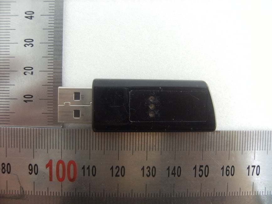
Click to zoom
Application Details
- Equipment Class
- DXX - Part 15 Low Power Communication Device Transmitter
- Date of Grant
- Apr 13, 2011
- Application Purpose
- Original Equipment
- Date of Application
- Apr 13, 2011
- Equipment Note
- Pentouch Dongle
- Frequency Range
- 2402.00000000 - 2480.00000000
- Company
- LG Electronics USA, Inc.
- Country
- United States
Documents & Files
Document Text
Text extracted from the exhibit documents filed with the FCC. Open a document above to read the original.
Users Manual
[KOREA] 목 차 1. LG Pentouch Dongle 의 개요 및 제원 (1) 개 요 (2) 제 원 2. 주의 사항 3. 고객지원 4. User notice (1) 개 요 이 LG Pentouch Dongle 은 PC에 접속하여 사용자가 가정이나 사무실에서 PDP TV에 직접 글이나 그림을 나타낼 수 있으며, 2.4GHz 대역의 무선방식을 LG Touch Pen과 연동하여 PDP 화면을 제어하는 수신부 제품 입니다 . (2) 제 원 구 분 내 용 모 델 명 AN-TD200 주파수 대역 2402MHz ~ 2480MHz 채 널 79EA 송신 출력 0 dBm 수신 감도 -82dBm 크 기 폭 18 x 두께9.5 x 52.9 (공차 ± 1mm) 무 게 6.14g 전 원 5V (USB 전원) 동작 온도 0°C ~ + 40 °C 1. LG Pentouch Dongle 의 개요 및 제원 LG Pentouch Dongle User Information (Model Name: AN-TD200) 2. 주의 사항 (1) LG Pentouch Dongle 구입 후 Touch Pen이 정상적으로 작동할 수 있도록 USB Dongle 드라이버 설치 방법에 따라 PC에 설치하세요 . (2) LG Pentouch Dongle 구입 후 제품 사용법에 따라 페어링 후에 사용 하세요 . (3) 제품을 분해하거나, 열을 가해서는 안됩니다. (4) 케이스가 손상될 정도로 극심한 충격을 줘서는 안됩니다. (5) 제품을 물에 넣어서는 안됩니다. 3. 고객 지원 (1) TV 매뉴얼의 서비스 연락처를 참조하세요. (2) 보증기간 : 1년 보증 기간 중에 정상적인 사용 중에 기술상의 결함이나 문제가 나타났을 때, 구입처를 방문하세요. 이 보증은 제품을 구매한 그 지역의 구매자에게만 적용됩니다. (3) KCC 인증 마크 및 인증번호 KCC-CMM-LGE-EBX615088 기자재의 명칭 (모델명) : 특정소출력무선 기기 (무선데이터 통신 시스템용 무선기기)/AN-TD200 상호명 : 엘지전자(주) 제조자 /제조국가: 엘지전자(주)/대한민국 제조년월: . . [ENGLISH] Contents 1. Overview and Specifications of LG Pentouch Dongle (1) Overview (2) Specifications 2. Cautions 3. Customer Support 4. User Notice (1) Overview This LG Pentouch Dongle allows you to access your PC and type text or draw a picture directly on the PDP TV at home or in the office. It is a receiver that controls the PDP screen by working with the LG Touch Pen using the 2.4 GHz wireless band. (2) Specifications Item Description Model Name AN-TD200 Frequency band 2402 MHz to 2480 MHz Channels 79 Tx power 0 dBm Reception sensitivity -82 dBm Size 18 x 9.5 x 52.9 (Tolerance ± 1 mm) Weight 6.14 g Power supply 5 V (USB power source) Operating temperature 0°C to +40°C 1. Overview and Specifications of LG Pentouch Dongle 2. Cautions (1) Install the LG Pentouch Dongle on your PC according to the USB dongle installation instructions; this allows the LG Touch Pen to work properly. (2) Start using the LG Pentouch Dongle by first pairing it with the TV, as instructed in the user manual. (3) Do not disassemble or heat the product. (4) Avoid extreme shocks to the product that can damage the case. (5) Do not put the product in water. 3. Customer Support (1) See the service contact in the TV manual. (2) Warranty period: 1 year If you find a technical defect or problem in the course of normal use during the warranty period, please contact your dealer. This warranty applies only to the purchaser in the region where the product is purchased. [GERMAN] Inhalt 1. Überblick und Spezifikationen des LG Pentouch Dongle (1) Überblick (2) Spezifikationen 2. Warnhinweise 3. Kundendienst 4. Hinweis für Benutzer (1) Überblick Mit dem LG Pentouch Dongle können Sie auf Ihren PC zugreifen und auf Ihrem PDP- Fernseher zu Hause oder im Büro direkt Text eingeben oder zeichnen. Es handelt sich um einen Empfänger, der den PDP-Bildschirm steuert. Dies geschieht im Zusammenspiel mit dem LG Touch Pen über die Drahtlosfrequenz 2,4 GHz. (2) Spezifikationen Element Beschreibung Modellname AN-TD200 Frequenzband 2.402 bis 2.480 MHz Kanäle 79 TX Power 0 dBm Empfängerempfindlichkeit -82 dBm Größe 18 x 9,5 x 52,9 (Toleranz ± 1 mm) Gewicht 6,14 g Stromversorgung 5 V (Stromversorgung über USB) Betriebstemperatur 0°C bis +40°C 1. Überblick und Spezifikationen des LG Pentouch Dongle 2. Warnhinweise (1) Schließen Sie den LG Pentouch Dongle an Ihren PC gemäß der USB-Dongle-Installationsanleitung an. Damit wird sichergestellt, dass der LG Touch Pen ordnungsgemäß funktioniert. (2) Wenn Sie den LG Pentouch Dongle zum ersten Mal verwenden, koppeln Sie ihn mit Ihrem Fernsehgerät wie in der Bedienungsanleitung beschrieben. (3) Bauen Sie das Produkt nicht auseinander, und erhitzen Sie es nicht. (4) Vermeiden Sie extreme Erschütterungen des Produkts, die das Gehäuse beschädigen können. (5) Bringen Sie das Produkt nicht mit Wasser in Berührung. 3. Kundendienst (1) Siehe Service-Kontakt in der Bedienungsanleitung Ihres Fernsehgeräts. (2) Garantiezeitraum: 1 Jahr Sollte bei normaler Verwendung während des Garantiezeitraums ein Defekt oder sonstiges Problem auftreten, wenden Sie sich an Ihren Fachhändler. Diese Garantie gilt nur für den Käufer in der Region, wo das Produkt gekauft wurde. [FRENCH] Sommaire 1. Présentation et spécifications du module de sécurité LG Pentouch Dongle (1) Présentation (2) Spécifications 2. Précautions 3. Support technique 4. Avertissement utilisateur (1) Présentation Le module de sécurité LG Pentouch Dongle vous permet d'accéder à votre PC et de saisir un texte ou de dessiner une image directement sur un téléviseur PDP à la maison ou au bureau. Il s'agit d'un récepteur qui contrôle l'écran PDP grâce à une interaction avec le stylet LG Touch Pen via une bande sans fil de 2,4 GHz. (2) Spécifications Élément Description Nom du modèle AN-TD200 Bande de fréquence De 2 402 à 2 480 MHz Canaux 79 Puissance d'émission 0 dBm Sensibilité de réception - 82 dBm Taille 18 x 9,5 x 52,9 (Tolérance ± 1 mm) Poids 6,14 g Alimentation électrique 5 V (Source d'alimentation USB) Température de fonctionnement De 0°C à + 40°C 1. Présentation et spécifications du module de sécurité LG Pentouch Dongle 2. Précautions (1) Installez le module de sécurité LG Pentouch Dongle sur votre PC en suivant les instructions d'installation du dongle USB afin que le stylet LG Touch Pen fonctionne normalement. (2) Utilisez tout d'abord le module de sécurité LG Pentouch Dongle en association avec votre téléviseur en suivant les instructions du guide de l'utilisateur. (3) N'essayez pas de désassembler ni de faire chauffer le produit. (4) Évitez tout choc violent avec produit. Cela pourrait endommager le boitier. (5) N'immergez pas le produit dans l'eau. 3. Support technique (1) Consultez le guide d'utilisation du téléviseur pour connaître les coordonnées du support technique. (2) Durée de la garantie : 1 an Si vous constatez un défaut ou un problème technique lors de l'utilisation normale du produit et que la garantie est toujours valable, cont…
Text truncated - open the document above for the full version.
Cover Letter(s)
LG Electronics USA. 1000 Sylvan Avenue Englewood Cliffs, New Jersey, United States Date: March 14, 2011 Compliance Certification Services Certification Division 47173 Benicia Street Fremont, CA 94538, USA To whom it may concern: I, the undersigned, hereby authorize Ms. Claire Hoque/Application Examiner of Compliance Engineering Services, Inc., d.b.a. Compliance Certification Services and hereafter referred to as CCS, to act on our behalf in all manners relating to application for equipment authorization, including signing of all documents relating to these matters. Any and all acts carried out by Ms. Claire Hoque of CCS on our behalf shall have the same effect as acts of our own. In authorizing CCS as our agent, we still recognize that we are responsible to: a) comply with the relevant provisions of the certification program; b) make all necessary arrangements for the conduct of the evaluation, including provision for examining documentation and access to all areas, records (including internal audit reports) and personnel for the purposes of evaluation (e.g. testing, inspection, assessment, surveillance, reassessment) and resolution of complaints; c) make claims regarding certification only in respect of the scope for which certification has been granted; d) do not use our product certification in such a manner as to bring the Certification Division into disrepute and not make any statement regarding our product certification which the Certification Division may consider misleading or unauthorized; e) upon suspension or cancellation of certification, discontinue use of all advertising matter that contains any reference thereto and return any certification documents as required by the Certification Division; f) use certification only to indicate the products are certified as being in conformity with specified standards;
Cover Letter(s)
LG Electronics USA. 1000 Sylvan Avenue Englewood Cliffs, New Jersey, United States Date: March 17, 2011 Compliance Certification Services Certification Division 47173 Benicia Street Fremont, CA 94538, USA RE: Request of Confidentiality for FCCID: BEJTD200 To Whom It may Concern: Pursuant to Sections 0.457 and 0.459 of the Commission`s Rules(CFR 47), and Section 552 (b) (4) of the Freedom of Information Act, LG Electronics USA. hereby requests confidentiality and treatment of certain information accompanying this application. The materials contain trade secrets and proprietary information not customarily released to the public. The public disclosure of these matters might be harmful to the Applicant and provide unjustified benefits to its competitors. We are also hereby request Short-Term Confidentiality for 180 days after the grant as outlined in Public Notice DA 04-1705. This provision will give LG Electronics USA. temporary confidentiality of commercially sensitive information prior to product release. The requested permanent and Short-Term Confidential exhibits are listed as follows: PERMANENT & SHORT-TERM CONFIDENTIAL LIST Exhibit Description File name PERMANENT 1 Block Diagram Block Diagram_BEJTD200.pdf 2 Operational Description Operational Description_BEJTD200.pdf 3 Schematics Schematic_BEJTD200.pdf 4 Part Lists Part List_BEJTD200.pdf SHORT-TERM 5 External Photos Ext Photo_BEJTD200.pdf 6 Internal Photos Int Photo_BEJTD200.pdf 7 Test-Setup Photos Test Photo_BEJTD200.pdf 8 Users Manual User Manual_BEJTD200.pdf Note: The pictures on the label location do not require any long term or short term confidentiality. The Applicant understands that pursuant to Rule 0.457, disclosure of this application and all accompanying documentations, where applicable, will not be public before the date of the Grant for this application. Sincerely, Christopher Johnson Sr. Manager, Standards & Compliance
Cover Letter(s)
LG Electronics USA. 1000 Sylvan Avenue Englewood Cliffs, New Jersey, United States Date: March 17, 2011 Compliance Certification Services Certification Division 47173 Benicia Street Fremont, CA 94538, USA LETTER OF AUTHORIZATION We, the undersigned, hereby authorize Harvey Sung of Digital EMC Co., Ltd. to act on our behalf in all manners relating to application for equipment authorization for FCC ID: BEJTD200 including signing of all documents relating to these matters. Any and all acts carried out by Harvey Sung of Digital EMC Co., Ltd. on our behalf shall have the same affect as acts of our own. This authorization is valid until further written notice from LG Electronics USA. Sincerely, Christopher Johnson Sr. Manager, Standards & Compliance
External Photos
FCCID: BEJTD200 Copyright Ⓒ 2011, Digital EMC Co., Ltd. View 1 FCCID: BEJTD200 Copyright Ⓒ 2011, Digital EMC Co., Ltd. View 2 FCCID: BEJTD200 Copyright Ⓒ 2011, Digital EMC Co., Ltd. View 3
ID Label/Location Info
FCC ID: BEJTD200 Copyright Ⓒ 2011, Digital EMC Co., Ltd. FCC ID SAMPLE LABEL & LOCATION LABELLING REQUIREMENTS PER §2.925 The Label shown shall be permanently affixed at a conspicuous location on the device and be readily visible to the user at the time of purchase - The FCC label shown is representative of the label that will appear on the radio when in production. Other information may also be included on this label. - The device is so small that it is not practicable to place the statement specified under 15.19 statement request, the information required by this paragraph shall be placed in a prominent location in the user's manual.
Internal Photos
FCCID: BEJTD200 Copyright Ⓒ 2011, Digital EMC Co., Ltd. Page1 / 3 View 1 FCCID: BEJTD200 Copyright Ⓒ 2011, Digital EMC Co., Ltd. Page2 / 3 View 2 FCCID: BEJTD200 Copyright Ⓒ 2011, Digital EMC Co., Ltd. Page3 / 3 View 3
Test Report
1103-00270 DRTFCC1103-0101 TRF-RF-215(00)110331 Page 2 / 17 Copyright ○ C 2011, Digital EMC Co., Ltd. CONTENTS 1. Equipment information .............................................................. 3 1.1 Equipment description ............................................................. 3 1.2 Ancillary equipment ................................................................. 3 2. Information about test items ..................................................... 4 2.1 Test mode ................................................................................ 4 2.2 Auxiliary equipment ................................................................. 4 2.3 Tested frequency ..................................................................... 4 2.4 Tested environment ................................................................. 4 2.5 EMI Suppression Device(s)/Modifications ............................... 4 3. Test Report ................................................................................. 5 3.1 Summary of tests .................................................................... 5 3.2 Transmitter requirements ........................................................ 6 3.2.1 AC Conducted Emissions .................................................... 6 3.2.2 Radiated Emission .............................................................. 9 3.2.3 Antenna Requirements ..................................................... 13 APPENDIX..................................................................................... 14 1103-00270 DRTFCC1103-0101 TRF-RF-215(00)110331 Page 3 / 17 Copyright ○ C 2011, Digital EMC Co., Ltd. 1. Equipment information 1.1 Equipment description FCC Equipment Class Part 15 Low Power Communication Device Transmitter Equipment type Pentouch Dongle Equipment model name AN-TD200 Equipment add model name N/A Equipment serial no. Identical prototype Frequency band 2402 ~ 2480MHz Power DC 5 V Antenna type Internal Type: PCB Antenna (Max. peak gain: 2.211 dBi) 1.2 Ancillary equipment Equipment Model No. Serial No. Manufacturer Note - - - - - - - - - - 1103-00270 DRTFCC1103-0101 TRF-RF-215(00)110331 Page 4 / 17 Copyright ○ C 2011, Digital EMC Co., Ltd. 2. Information about test items 2.1 Test mode This device was tested in maximum duty and maximum power. Test Case 1 - Test Case 2 - Test Case 3 - 2.2 Auxiliary equipment Equipment Model No. Serial No. Manufacturer Note Notebook X51RL 85N0AS318314227 ASUS - - - - - - 2.3 Tested frequency TX Frequency (MHz) RX Frequency (MHz) Lowest Channel 2402 2402 Middle Channel 2439 2439 Highest Channel 2480 2480 2.4 Tested environment Temperature : 21 ~ 23 o C Relative humidity content : 36 ~ 55 % R.H. Details of power supply : DC 5 V AC-DC Adapter : AC 120 V 60 Hz 2.5 EMI Suppression Device(s)/Modifications EMI suppression device(s) added and/or modifications made during testing → None 1103-00270 DRTFCC1103-0101 TRF-RF-215(00)110331 Page 5 / 17 Copyright ○ C 2011, Digital EMC Co., Ltd. 3. Test Report 3.1 Summary of tests FCC Part Section(s) Parameter Limit (Using in 2400 ~ 2483.5MHz) Test Condition Status Note 1 I. Transmit mode (Tx) 15.249 (a) Field Strength Limits Refer to the FCC 15.249(a) Radiated C Note.2 15.205, 15.209 General Field Strength Limits (Restricted Bands and Radiated Emission Limits) < FCC 15.209 limits Radiated C Note.2 15.207 AC Conducted Emissions < FCC 15.207 limits Line Conducted C Note 1: C=Comply NC=Not Comply NT=Not Tested NA=Not Applicable Note 2: This test item was performed in each axis. and the worst case data were reported. The sample was tested according to the following specification: ANSI C-63.4-2003 1103-00270 DRTFCC1103-0101 TRF-RF-215(00)110331 Page 6 / 17 Copyright ○ C 2011, Digital EMC Co., Ltd. 3.2 Transmitter requirements 3.2.1 AC Conducted Emissions - Procedure: The conducted emissions are measured in the shielded room with a spectrum analyzer in peak hold. While the measurement, EUT had its hopping function disabled at the middle channels in line with Section 15.31(m). Emissions closest to the limit are measured in the quasi-peak and average detector mode with the tuned receiver using a bandwidth of 9 kHz. The emissions are maximized further by cable manipulation and Exerciser operation. The highest emissions relative to the limit are listed. - Measurement Data: Comply Minimum Standard: FCC Part 15.207(a) Frequency Range (MHz) Conducted Limit (dBuV) Quasi-Peak Average 0.15 ~ 0.5 66 to 56 * 56 to 46 * 0.5 ~ 5 56 46 5 ~ 30 60 50 * Decreases with the logarithm of the frequency 1103-00270 DRTFCC1103-0101 TRF-RF-215(00)110331 Page 7 / 17 Copyright ○ C 2011, Digital EMC Co., Ltd. AC Line Conducted Emissions (Graph) 1103-00270 DRTFCC1103-0101 TRF-RF-215(00)110331 Page 8 / 17 Copyright ○ C 2011, Digital EMC Co., Ltd. AC Line Conducted Emissions (Data List) 1103-00270 DRTFCC1103-0101 TRF-RF-215(00)110331 Page 9 / 17 Copyright ○ C 2011, Digital EMC Co., Ltd. 3.2.2 Radiated Emission - Procedure: The EUT was placed on a 0.8m high wooden table inside a semi anechoic chamber. An antenna was placed at 3m distance from the EUT. Measurements of frequencies and amplitudes of field strengths were recorded for reference during final measurements. For final radiated testing, measurements were performed on OATS. Measurements were performed with the EUT oriented in 3 orthogonal axis and rotated 360 degrees to determine worst-case orientation for maximum emissions The spectrum analyzer is set to: Frequency Range = 30 MHz ~ 10 th harmonic. RBW = 100 kHz ( 30MHz ~ 1 GHz) = 1 MHz (1 GHz ~ 10 th harmonic ) VBW ≥ RBW Distance = 3m Detector function = peak Trace = max hold Sweep = auto Measurement Data: Comply Note 1: See next pages for actual measured spectrum plots and data. Fundamental / Harmonics emission: FCC Part 15.249(a) Frequency (MHz) Limit @ 3m Fundamental (mV/m) Harmonics (uV/m) 2400 ~ 2483.5 50 500 General Standard: FCC Part 15.209(a) Frequency (MHz) Limit (uV/m) @ 3m 30 ~ 88 100 ** 88 ~ 216 150 ** 216…
Text truncated - open the document above for the full version.
Test Setup Photos
FCC ID: BEJTD200 Copyright Ⓒ 2011, Digital EMC Co., Ltd. Tested EUT Position EUT position: X axis EUT position: Y axis EUT position: Z axis FCC ID: BEJTD200 Copyright Ⓒ 2011, Digital EMC Co., Ltd. View 1 FCC ID: BEJTD200 Copyright Ⓒ 2011, Digital EMC Co., Ltd. View 2
Contact Information
Applicant
David Kim(Team leader, LGEUS NA Policy & Regulatory Affairs)
Technical Contact
Digital EMCHarvey Sung
[email protected]+82-31-321-1664
683-3 Yuban-Dong · Yongin-Si, Kyunggi-Do · South Korea
Test Firm
DT&C Co.,Changho Lee
Technical Specifications
| # | Rule Parts | Frequency Range | Power Output |
|---|---|---|---|
| 1 | 15C | 2.40 GHz - 2.48 GHz | - |
Other Applications from LG Electronics USA, Inc.

BEJTFHOBINI1F1
Jan 08, 2025Telematics
Equipment Class
DTS - Digital Transmission SystemBEJNT-16Z90TS
Oct 02, 2024Notebook Computer
Equipment Class
DSS - Part 15 Spread Spectrum TransmitterBEJSP-PEW8
Sep 26, 2024Stylus Pen
Equipment Class
DCD - Part 15 Low Power Transmitter Below 1705 kHzBEJ-RSMV2
Sep 24, 2024RF Module
Equipment Class
FDS - Part 15 Field Disturbance SensorBEJTFBMEIBN3EU
Sep 24, 2024Telematics
Equipment Class
NII - Unlicensed National Information Infrastructure TX