BEK9E3UB16Bodypack Transmitter
Promark International, Inc.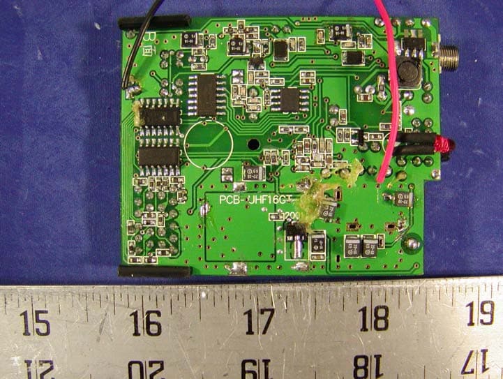
Click to zoom
Application Details
- Equipment Class
- TBT - Licensed Broadcast Transmitter Worn on Body
- Date of Grant
- Jun 30, 2002
- Application Purpose
- Original Equipment
- Date of Application
- Jun 30, 2002
- Equipment Note
- Bodypack Transmitter
- Frequency Range
- 726.00000000 - 745.90000000
- Company
- Promark International, Inc.
- Country
- United States
Documents & Files
Document Text
Text extracted from the exhibit documents filed with the FCC. Open a document above to read the original.
Users Manual
Preliminary 01/02 UB-16 UHF Wireless Microphone and Instrument System 16 Channel PLL Frequency Synthesized OWNER’S MANUAL TABLE OF CONTENTS: FCC Warning Statement A. INTRODUCTION Using this Manual B. SYSTEM FEATURES UB-16 C. OPERATING INSTRUCTIONS UB-16 Bodypack Transmitter 1. Powering the Transmitter 2. Selecting Input for Operation 3. Connecting the Audio Source 4. Turning on the Transmitter 5. Selecting the Operating Frequency 6. Selecting the Tone Squelch™ Mode 7. Locking the Keyboard 8. Microphone and Instrument Operation a. Instrument Use b. Microphone Use D. FREQUENCY GUIDE E. CHANNEL DISPLAY AND UP/DOWN BUTTONS OPERATION 1. UB-16 Transmitters a. Changing the Channel Assignment b. Selecting Tone Squelch™ Mode c. Selecting Keyboard Lock F. SPECIFICATIONS UB-16 Transmitters G. SERVICE FOR YOUR NADY WIRELESS SYSTEM U.S. International FCC RF Exposure Statement This device complies with FCC radiation exposure limits as set forth for an uncontrolled environment. This device should be installed and operated so that its antenna(s) are not co-located or operating in conjunction with any other antenna or transmitter. Preliminary 01/02 A. INTRODUCTION Thank you for choosing the Nady UHF 16 wireless system, and congratulations on your choice. The Nady UHF 16 systems are by far the best performance and price value available in professional UHF wireless. Offering clear channel operation on the wide open, uncluttered UHF band for interference-free performance in any application or locale, the UHF 16 delivers 16 user switchable, frequency synthesized channels in pre-programmed groups in the 726 - 865 MHz range. The UHF 16 systems feature Nady's proprietary companding and low noise circuitry for an industry best 120 dB Dynamic Range, and the clearest, most natural sound available in wireless today. Using this Manual This booklet gives instructions for the operation of the UHF 16 systems, including the UB-16 Bodypack Transmitter, and the UH-16 Handheld Microphone Transmitter. Please read this instruction booklet completely before operating your system, and refer to the Nady UHF 16 Frequency Guide for the frequency band(s) and channels utilized by your system. This manual will first explain the benefits of the UHF 16 and then will take you step by step on how to operate your new system. Each section will give you detailed information. Also, included in this manual is the frequency selection chart, complete system specifications, and servicing information. B. SYSTEM FEATURES UB-16 Transmitters Choice of transmitters: UH-16 handheld or UB-16 bodypack, both 16-channel selectable • UB-16 operates on 2 AA batteries for the longest reliable and economical battery life. • UB-16 bodypack is a versatile unit with unique 3-way input switch allowing it operation selectively as an instrument, lavalier mic, or headworn mic transmitter (with convenient DC phantom powering in the mic settings for condensers). An input level control allows optimal audio gain adjustment, and a locking 3.5 mm jack provides secure connection to the instrument cable, lavalier or headworn mic cord. • UB-16 transmitters features OFF/STANDBY/On controls, low battery LED indicators, and offer easy channel selection via UP/DOWN buttons and a 2- segment LED Channel display. C. OPERATING INSTRUCTIONS UB-16 Bodypack Transmitter 1. Powering the Transmitter Slide open the BATTERY COMPARTMENT (19) and insert 2 fresh AA ALKALINE BATTERIES (20), observing the correct polarity. AA AA Preliminary 01/02 Two fresh alkaline batteries can last up to 12 hours in use, but in order to ensure optimum performance, it is recommended that the battery be replaced after 8-10 hours of use. 2. Selecting Input for Operation The UB-16 is equipped with an INPUT SELECTOR SWITCH (21) in the battery compartment for selecting the type of audio input you will be supplying to the transmitter. Select from the choice of three positions: GT (for guitar, bass, etc.) / HM (for headworn mic)/ LT (for lavalier mic). 3. Connecting the Audio Source The UB-16 is provided with a 3.5 mm LOCKING JACK (22) for connecting the audio input selected. Connect either the INSTRUMENT CORD (23) or the HEADWORN MIC (24) or LAVALIER MIC CORD (25) as desired, according to the input selected. (Note: Use only the input audio source as per the input selected with the AUDIO INPUT SELECTOR SWITCH or the audio will not be optimal– a muddy or distorted sound may result.) To secure the connection, turn the slip ring on the plug clock wise to thread it on the jack. To unplug, reverse the process. Slip the transmitter into a pocket or CLIP (26) it on to your clothes or instrument strap (if using the UB-16 as an instrument transmitter). 4. Turning on the Transmitter Turn on the UB-16 by sliding the OFF/STANDBY/ON SWITCH (26) to the STANDBY position (transmitter on, audio muted) or the ON position (transmitter and audio both on). The BATTERY INDICATOR LED (27) will give a single quick flash, indicating usable battery strength. In the case of dead or low batteries, the LED either will not go on at all or will stay on continuously, indicating that the batteries should be replaced with fresh ones. To preserve battery life; turn the transmitter off when not in use. Inside the cover, the channel number on the CHANNEL LED DISPLAY (29) will extinguish in 10 seconds. The activity indicator “ “ or “ “ LED will remain on. 5. Selecting the Operating Frequency In order for the system to operate properly the same channel (frequency of operation) must be selected for the UB-16 transmitter as was chosen for the UHF-16 receiver. Press either the UP or DOWN CHANNEL SELECT BUTTON (28) until the channel number indicated on the 2-segment CHANNEL LED DISPLAY (29) matches that of the UHF- 16 receiver. 6. Selecting the Tone Squelch™ Mode Hold both the UP and DOWN BUTTONS (28) at the same time for 1 second. The Tone Squelch™ will cycle from On to Off. See the CHANNEL DISPLAY AND UP/DOWN BUTTON OPERATION section below. 7. Locking the K…
Text truncated - open the document above for the full version.
Cover Letter(s)
April 1, 2002 Federal Communications Commission Authorization and Evaluation Division Confidentiality Request regarding application for certification of FCC ID: BEK9E3UB16. Pursuant to Sections 0.457 and 0.459 of the Commission’s Rules, we hereby request confidential treatment of information accompanying this application as outlined below: - Schematics The above materials contain trade secrets and proprietary information not customarily released to the public. The public disclosure of these materials may be harmful to the applicant and provide unjustified benefits to its competitors. The applicant understands that pursuant to Section 0.457 of the Rules, disclosure of this application and all accompanying documentation will not be made before the date of the Grant for this application. Sincerely,
External Photos
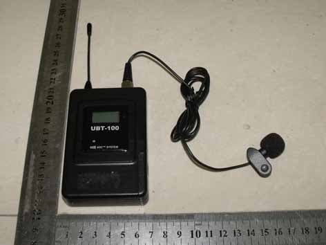
EUT PHOTOGRAPHS Chassis - Front View Chassis - Rear View
ID Label/Location Info
FCC ID LABELING AND LOCATION Proposed FCC ID Labeling Proposed FCC ID Location Front Side of EUT/Proposed FCC ID Location FCC ID: BEK9E3UB16
Internal Photos
APPENDIX C - EUT PHOTOGRAPHS Main Board - Component View Main Board - Solder View Transmitter - Component View
Operational Description
UHF-16 Circuit Description A. TX Part 1. low freq Amplify Part: MIC change tone signal through U9A amplify enter U9B lowpass amplify to ‘VD2 be FM modulate. U2, R39, C5 combine to be an automatic level control (ALC). 2. Select guide freq Part: From CPU transmit signal through U10B, U10C, U6A, U6B network change to U6D, then enter FM modulate. 3. VCO Part: ‘Q4, ‘VD1, “VD2 become VCO, frequency change through PLL control transfiguration diode ‘VD2, VD1 change, Q5 represent MIC signal change,VCO signal transmit signal TX amplify, another signal through back U1 inspection from U1 10 PIN transmit tolerant voltage to give VD2, VD1 control VCO voltage to have a result of control the voltage. 4. Efficiency Amplify Part: ‘Q3 is amortize Amp, ‘Q2 is drive Amp ‘Q1 is power Amp, the signal through ‘Q1 amplify through antenna transmit. B. RX Part 1. RF Part: Antenna receive signal through ‘C83, ‘;C84, D1, R33, L1, C39 combine to LPF network, ‘Q3 amplify, enter BPF, after choose-frequency enter frequency conversion ‘Q4. 2. VCO and frequency conversion Part: ‘Q4 is frequency conversion VCO made by monofier of the machine , and frequency control by PLL, after ‘CF2, transmit 45.36 MHZ, 3. IF Part: ‘CF3 is 10.7 MHZ BPF‘Q9 is the first intermediare freq Amplify, the second intermediare freq is 10.7 MHZ, U5 respond freq conversion, monfier of the machine, intetmediare freq Amp,denodulation, MUTE control etc. 4. MUTE Part: Through DU5 7 PIN transmit, RC LPF, U10 (LM339) U10A 4pin and U10B7 transmit compare, 14pin transmit and Q11 C transmit. 5. Lowfreq Amplify Part: U11 make HPF (don’tguide inter) circuit, . 6. Tone Partl Signal through U11A, Front b amplify enter U8 33179 power Amp, Q14, Q15 become MC33179 signal control trode 7. Guide Part: X6, X5 combine to be LPF (Don’t tone inter) circuit, after transfer to U9B send to CPU decode C. Other Part 1. PLL Part: PLL from ‘U1 (LMX1601) respond, ‘X4 is timer crystal, ‘Vc1 is adjust capacitor, make the monofier frequency stay on 12.8MHZ, ‘U1 10pin transmit steady current control VCO monofier frequency; make decision from the internal procedure of CPU. 2. LCD Part: LCD display is responded from HT-4631, the work under the adjust format, frequency is 32.768KHZ and 4 MHZ, the display content is make decision from the internal procedure of CPU. 3. CPU Part: RX W742E81A is 4-bit and TX PIC16C6C621A PC is the core part of the full circuit, the function would operate from each function key.
Parts List/Tune Up Info
TUNING PROCEDURE UB16 Body Pack Transmitter UB16 Transmitter: 1: The following items are adjusted and measured according to scheme 1 a) RF Power Typical result = 13 dBm b) RF Frequency Typical result, CH 1 = 726.00 MHz, CH 16 = 745.90 MHz Adjustment = VC1 for correct frequency c) Drain Current Typical result = 120 mA d) Harmonics Typical result, Fx2 <-40 dBm, Fx3 <-45 dBm, others <-65 dBm e) Spurious Typical result = <-40 dBm f) Low Battery on Typical result = 2.2V g) VCO Voltage Typical result, CH 1=0.8V, CH 16=2.22V Adjustment = VC2 to center VCO control voltage range. (Scheme 1) 50 Ω Coaxial Cable Power mA Meter VDD TP2 TX Board ANT Spectrum Analyzer Voltage Meter 2: The following items are measured according to scheme 2 a) Pilot Tone Frequency Typical result, Tone 1= 32.768 KHz Tone 2= 30.720 KHz b) Pilot Tone Modulation Deviation Typical result = 6 KHz c) 1 kHz Audio Tone Modulation Distortion Typical result = <1 % (Scheme 2) 50Ω Coaxial Cable 3: The following items are adjusted and measured according to scheme 3 a) Normal Deviation Typical result = 25 KHz for UHT-16 = 24 mV RMS At 400 Hz UB-16 = 225 mV RMS Adjustment = VR1 for microphone level b) Maximum Deviation Typical result = 200 KHz Power VDD MIC TX Board ANT Radio Communication Analyzer Sinewave Oscillator Oscilloscope Frequency Counter Distortion Meter (Scheme 3) 50 Ω Coaxial Cable Power VDD MIC TX Board ANT Sinewave Oscillator Modulation Meter Oscilloscope
Test Report
Note: This test report is specially limited to the above client company and the product model only. It may not be duplicated without prior written consent of Bay Area Compliance Laboratory Corporation. This report must not be used by the client to claim product endorsement by NVLAP or any agency of the U.S. Government. FCC PART 74 EMI MEASUREMENT AND TEST REPORT For Nady Systems, Inc. 6701 Shellmond Street Emeryville, CA 94608 USA FCC ID: BEK9E3UB16 March 26, 2002 This Report Concerns: Original Report Equipment Type: Transmitter Test Engineer: Benjamin Jing Report No.: R0201189 Test Date: February 5, 2002 Reviewed By: Jeff Lee Prepared By: Bay Area Compliance Laboratory Corporation 230 Commercial Street Sunnyvale, CA 94085 Tel: (408) 732-9162 Fax: (408) 732 9164 Nady Systems, Inc. FCC ID: BEK9E3UB16 Report # R0201189Rpt FCC Part 74 Test Report Page 2 of 19 TABLE OF CONTENTS 1 - GENERAL INFORMATION..................................................................................................................................3 1.1 PRODUCT DESCRIPTION FOR EQUIPMENT UNDER TEST (EUT) ..............................................................................3 1.2 OBJECTIVE.............................................................................................................................................................3 1.3 TEST METHODOLOGY............................................................................................................................................3 1.4 TEST FACILITY.......................................................................................................................................................3 1.5 TEST EQUIPMENT LIST...........................................................................................................................................4 2 - REQUIREMENTS OF PROVISIONS ...................................................................................................................5 2.1 DEFINITION............................................................................................................................................................5 2.2 FREQUENCIES AVAILABLE.....................................................................................................................................5 2.3 REQUIREMENTS AND TEST SUMMARY...................................................................................................................6 2.4 LABELING REQUIREMENT......................................................................................................................................6 3 - OUTPUT POWER MEASUREMENT ..................................................................................................................7 3.1 PROVISION APPLICABLE.........................................................................................................................................7 3.2 TEST PROCEDURE..................................................................................................................................................7 3.3 TEST EQUIPMENT...................................................................................................................................................7 3.4 TEST RESULTS.......................................................................................................................................................7 4 - MODULATION CHARACTERISTICS ................................................................................................................9 4.1 PROVISION APPLICABLE.........................................................................................................................................9 4.2 TEST PROCEDURE..................................................................................................................................................9 4.3 TEST EQUIPMENT...................................................................................................................................................9 4.4 TEST RESULTS.......................................................................................................................................................9 5 - OCCUPIED BANDWIDTH OF EMISSION.......................................................................................................11 5.1 PROVISION APPLICABLE.......................................................................................................................................11 5.2 TEST PROCEDURE................................................................................................................................................11 5.3 TEST EQUIPMENT.................................................................................................................................................11 5.4 TEST RESULTS.....................................................................................................................................................11 5.4 EMISSION DESIGNATOR........................................................................................................................................11 6 - FIELD STRENGTH OF EMISSION ...................................................................................................................14 6.1 PROVISION APPLICABLE.......................................................................................................................................14 6.2 TEST PROCEDURE................................................................................................................................................14 6.3 TEST EQUIPMENT.................................................................................................................................................15 6.4 TEST RESULTS............................................................................................................................…
Text truncated - open the document above for the full version.
Contact Information
Applicant
Kenneth Orlando(President)
Test Firm
Bay Area Compliance LaboratoryJohn Chan
Technical Specifications
| # | Rule Parts | Frequency Range | Power Output | Emission | Tolerance |
|---|---|---|---|---|---|
| 1 | 74.861 | 726 MHz - 745.9 MHz | 17.00 mW | 83K0F3E | 50.0000000000 ppm |
Other Applications from Promark International, Inc.
BEK9E3UBT
Sep 12, 2010Wireless Microphone
Equipment Class
TBT - Licensed Broadcast Transmitter Worn on BodyBEK9E3UHT
Sep 09, 2010Wireless Microphone
Equipment Class
TBF - Licensed Broadcast Transmitter Held to Face
BEK9E3UB-42
Dec 30, 2009WIRELESS MICROPHONE
Equipment Class
DXX - Part 15 Low Power Communication Device Transmitter
BEK9E3UH-42
Dec 30, 2009WIRELESS MICROPHONE
Equipment Class
DXX - Part 15 Low Power Communication Device Transmitter
BEK9E3UH4
Jan 17, 2005Wireless Microphone
Equipment Class
TNF - Licensed Non-Broadcast Transmitter Held to Face