BEK9E3WHTWireless microphone
Promark International, Inc.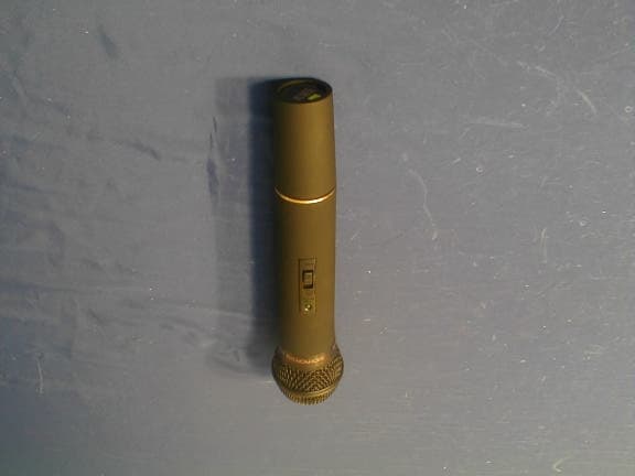
Click to zoom
Application Details
- Equipment Class
- TBC - Licensed Broadcast Station Transmitter
- Date of Grant
- Jul 25, 2001
- Application Purpose
- Original Equipment
- Date of Application
- Jul 25, 2001
- Equipment Note
- Wireless microphone
- Frequency Range
- 174.70000000 - 196.50000000
- Company
- Promark International, Inc.
- Country
- United States
Documents & Files
Document Text
Text extracted from the exhibit documents filed with the FCC. Open a document above to read the original.
Users Manual
User Manual Congratulations on your purchase. The NADY WHT-15 is the perfect entry level professional wireless, and delivers clear, transparent audio for a variety of singing and speech applications. Although offered at a breakthrough new low price for a professional wireless, this system is loaded with features: • High-band VHF (174.71 MHz~ 196.51 MHz) operation for interference-free performance. • Companding circuitry for a wide dynamic range (no overloading for loud inputs or background his s during quiet use) • Full frequency response from 40-20, 000 Hz • 250 ft. typical, up to 500 ft. line-of-sight operating range WHT-15 Handheld MIC transmitter 1. Unscrew the BATTERY COMPARTMENT COVER (1) and remove, exposing the BATTERY HOLDER (2). Insert a fresh 9V BATTERY (5), observing correct polarity as marked, and screw the cover back on to the microphone. To ensure proper battery contact, the cover must be screwed on completely. 2. Turn on the WHT-15 by sliding the OFF/STANDBY/ON SWITCH (3) to the STANDBY position (transmitter on, audio muted) or the ON position (transmitter and audio both on). The BATTERY INDICATOR LED (4) will give a single quick flash, indication usable battery strength. In the case of a dead or low battery, the LED will either not go on at all or will stay on continuously, indicating that the battery should be replaced with a fresh one. 3. The microphone is now ready to use. When ready to speak, slide the transmitter switch to the ON position and adjust the mixing board volume level as needed. FCC Part 74 Rules The equipment user is required by radio service rules to obtain a license before operating the equipment. The equipment is only for broadcast use. 1 3 4 2 5
Cover Letter(s)
Nady System, Inc. FCC ID: BEK9E3WHT Report # Test Report FCC Part 74 Test Report Page 22 of 22
External Photos
EUT Overall View
ID Label/Location Info
Proposed FCC ID Proposed FCC ID Label Location FCC ID: BEK9E3WHT Proposed FCC ID Location
Internal Photos
EUT – Main Board Component View EUT – Main Board Solder View
Parts List/Tune Up Info
Tuning Procedure 1. Tune C48, C46, C42, T3, T2, T1 to maximize the main wave output and syntony wave minimize. 2. The frequency is determined and stabilized by the crystal. Ranged from 174.71 MHz ~ 196.51 MHz is met and fixed by the proper crystal frequency. As the cartridge doesn’t have high sensitivity so there is no such kind a circuit for suppression of spurious radiation, and limiting modulation. 3. As the output power is usually less than 15 dBm, there is no circuit for limiting power. If it is necessary to lower the power then please change L4 to be a resistor or get the R37’s value higher.
Test Report
Note: This report may not be duplicated without prior written consent of Bay Area Compliance Laboratory Corporation. This report must not be used by the client to claim product endorsement by NVLAP or any agency of the U.S. Government. FCC PART 74 EMI MEASUREMENT AND TEST REPORT For Nady Systems, Inc. 6701 Shellmond Street Emeryville, CA 94608 USA FCC ID: BEK9E3WHT May 31, 2001 This Report Concerns: Original Report Equipment Type: Wireless Microphone – Household Appliance Test Engineer: Victor Liu / Jeff Lee Test Date: May 15, 2001 Reviewed By: John Y. Chan – Engineering Manager Prepared By: Bay Area Compliance Laboratory Corporation 230 Commercial Street, Suite 2 Sunnyvale, CA 94085 Tel: (408) 732-9162 Fax: (408) 732 9164 Nady System, Inc. FCC ID: BEK9E3WHT Report # Test Report FCC Part 74 Test Report Page 2 of 22 TABLE OF CONTENTS 1 - GENERAL INFORMATION.................................................................................................................................................3 1.1 PRODUCT DESCRIPTION FOR EQUIPMENT UNDER TEST (EUT)........................................................................................3 1.2 OBJECTIVE................................................................................................................................................................................3 1.3 TEST METHODOLOGY..............................................................................................................................................................3 1.4 TEST FACILITY.........................................................................................................................................................................3 1.5 TEST EQUIPMENT LIST............................................................................................................................................................4 1.6 EQUIPMENT UNDER TEST (EUT)...........................................................................................................................................4 2 – REQUIREMENTS OF PROVISIONS...............................................................................................................................5 2.1 DEFINITION...............................................................................................................................................................................5 2.2 FREQUENCIES AVAILABLE......................................................................................................................................................5 2.3 REQUIREMENTS AND TEST SUMMARY..................................................................................................................................5 2.4 LABELING REQUIREMENT.......................................................................................................................................................5 3 – OUTPUT POWER MEASUREMENT...............................................................................................................................6 3.1 PROVISION APPLICABLE.........................................................................................................................................................6 3.2 TEST PROCEDURE....................................................................................................................................................................6 3.3 TEST EQUIPMENT......................................................................................................................................................................6 3.4 TEST RESULTS..........................................................................................................................................................................6 4 - MODULATION CHARACTERISTICS...........................................................................................................................10 4.1 PROVISION APPLICABLE.......................................................................................................................................................10 4.2 TEST PROCEDURE..................................................................................................................................................................10 4.3 TEST EQUIPMENT...................................................................................................................................................................10 4.4 TEST RESULTS........................................................................................................................................................................11 5 - OCCUPIED BANDWIDTH OF EMISSION...................................................................................................................12 5.1 PROVISION APPLICABLE.......................................................................................................................................................12 5.2 TEST PROCEDURE..................................................................................................................................................................12 5.3 TEST EQUIPMENT...................................................................................................................................................................12 5.4 TEST RESULTS........................................................................................................................................................................12 6 - FIELD STRENGTH OF EMISSION.................................................................................................................................16 6.1 PROVISION APPLICABLE.......................................................................................................................................................16 6.2 TEST PROCEDURE.....................................…
Text truncated - open the document above for the full version.
Test Setup Photos
Radiated Emission Setup – Front View Radiated Emission Setup – Rear View
Contact Information
Applicant
Kenneth Orlando(President)
Technical Contact
Bay Area Compliance Laboratory Corp.John Chan
[email protected]408-732-9162
230 Commercial St. · Sunnyvale,, California · United States
Non-Technical Contact
Bay Area Compliance Laboratory Corp.Rita Cai
[email protected]408-732-9162
Test Firm
Bay Area Compliance LaboratoryJohn Chan
Technical Specifications
| # | Rule Parts | Frequency Range | Power Output | Emission | Tolerance |
|---|---|---|---|---|---|
| 1 | 74 | 174.7 MHz - 196.5 MHz | 400.00 µW | 50K0F3E | 0.0030000000 % |
Other Applications from Promark International, Inc.
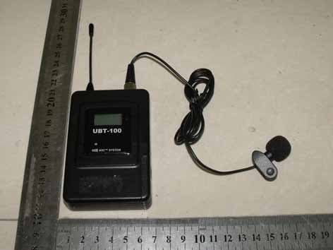
BEK9E3UBT
Sep 12, 2010Wireless Microphone
Equipment Class
TBT - Licensed Broadcast Transmitter Worn on BodyBEK9E3UHT
Sep 09, 2010Wireless Microphone
Equipment Class
TBF - Licensed Broadcast Transmitter Held to Face
BEK9E3UB-42
Dec 30, 2009WIRELESS MICROPHONE
Equipment Class
DXX - Part 15 Low Power Communication Device Transmitter
BEK9E3UH-42
Dec 30, 2009WIRELESS MICROPHONE
Equipment Class
DXX - Part 15 Low Power Communication Device Transmitter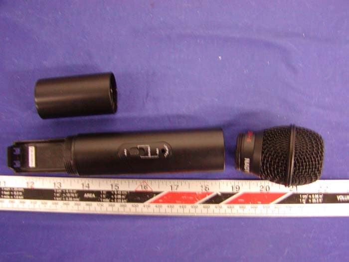
BEK9E3UH4
Jan 17, 2005Wireless Microphone
Equipment Class
TNF - Licensed Non-Broadcast Transmitter Held to Face