BOUAD905WWIRELESS SPEAKER SYSTEM
Philips Consumer Lifestyle
Click to zoom
Application Details
- Equipment Class
- DXX - Part 15 Low Power Communication Device Transmitter
- Date of Grant
- Feb 23, 2004
- Application Purpose
- Original Equipment
- Date of Application
- Feb 23, 2004
- Equipment Note
- WIRELESS SPEAKER SYSTEM
- Frequency Range
- 914.10000000 - 915.30000000
- Company
- Philips Consumer Lifestyle
- Country
- Hong Kong
Documents & Files
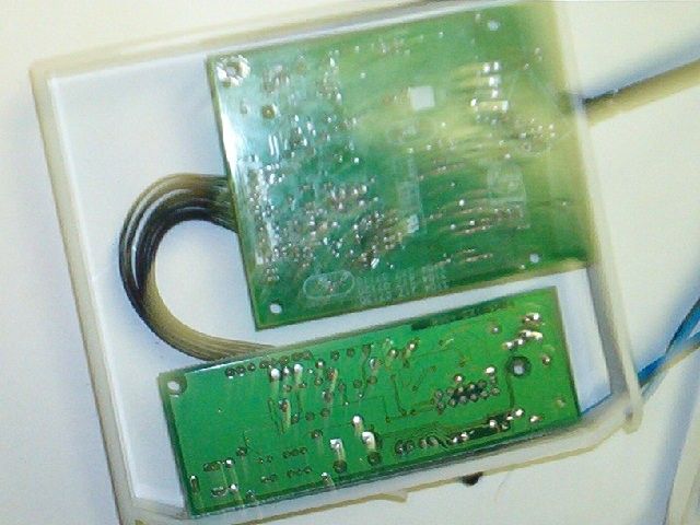
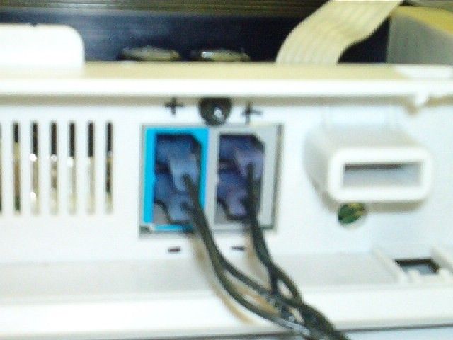
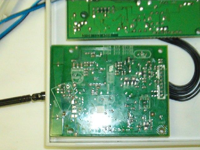
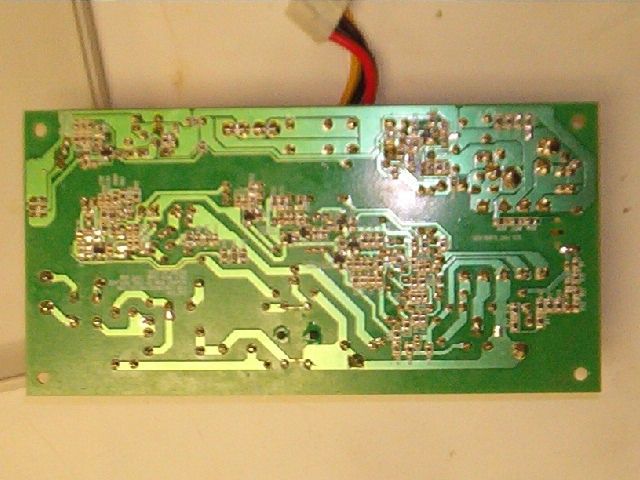
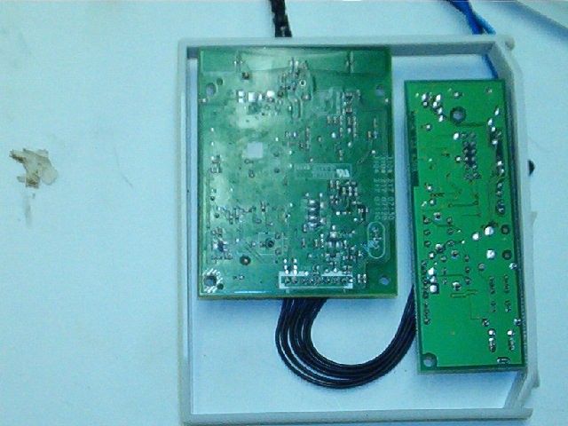
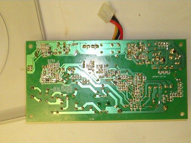
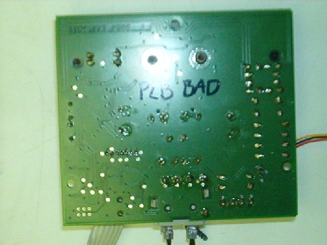
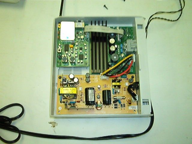
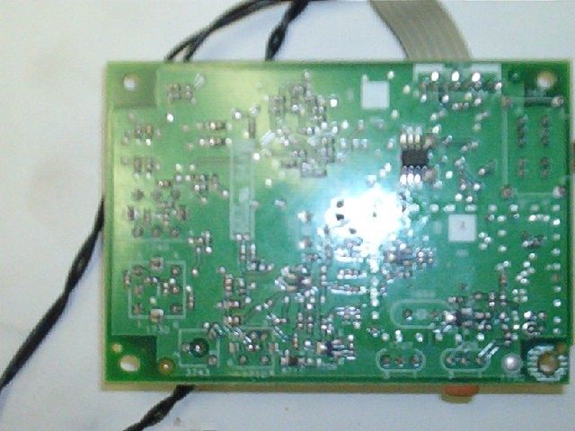

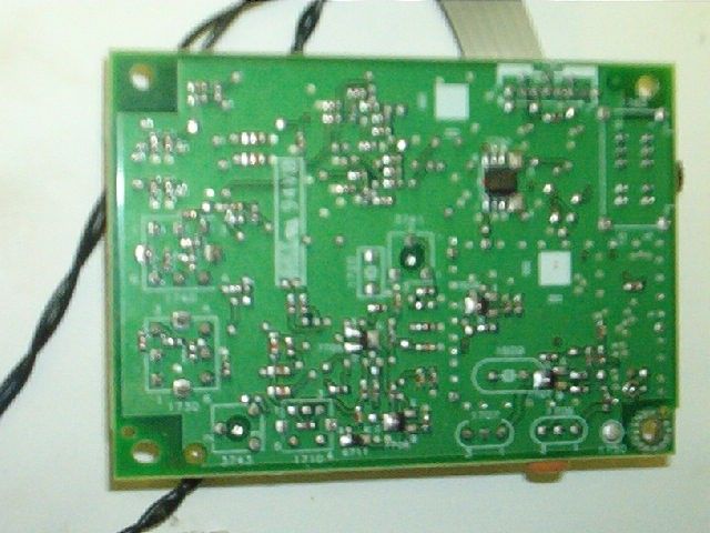
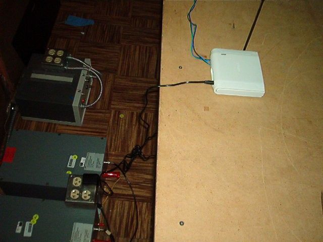
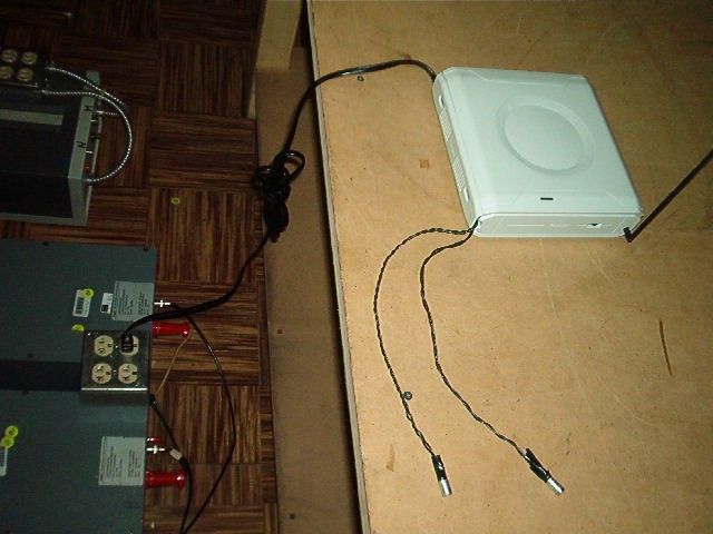
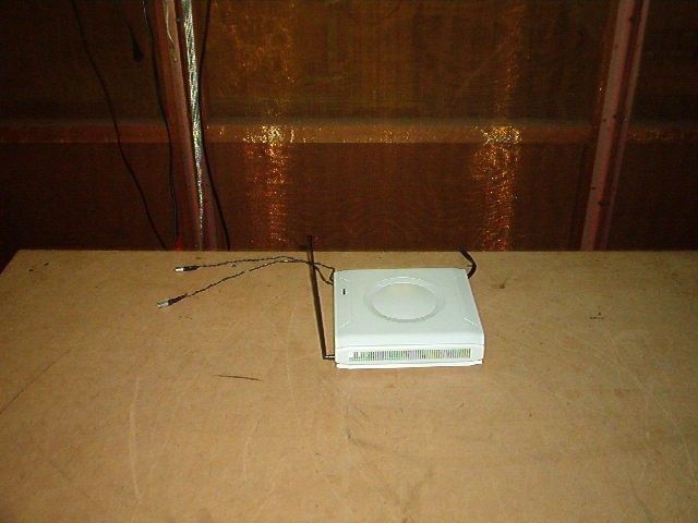
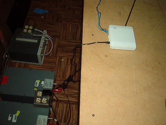
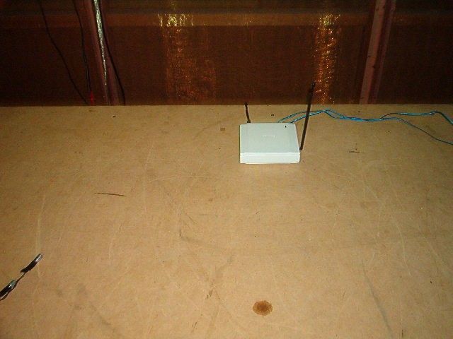
Document Text
Text extracted from the exhibit documents filed with the FCC. Open a document above to read the original.
Users Manual
IFU AD905W Author: JDR/EDN Date: 30/11/2002 Instruction For Use (IFU) for Wireless Audio set AD905W a) Unpack all parts: transmitter, receiver/amplifier, 14V adapter, table stand b) Connect the rear speakers terminals to the appropriate connector sockets of the receiver/amplifier. c) Place the receiver/amplifier unit at a minimum of 30cm above ground to avoid bad wave propagation; use the table stand as shown in the picture d) Connect receiver/amplifier to mains by use of power cord. e) Green led receiver/amplifier should light f) If led is not lighting, shift small power switch next to the connectors to the ON position. Green led should light now. g) Place the transmitter unit at a minimum of 30cm above ground to avoid bad wave propagation. Make sure transmitter and receiver are not closer than 2m from each other. h) Connect the 14V power adapter to the transmitter i) Connect transmitter-inputs to DVD surround – output. Be sure to connect right input to right output connector of DVD, idem for left channel? Mach the Blue and Grey colour. j) Power up the transmitter. Red led of transmitter unit should light now. k) Make sure that transmitter and Receiver/amplifier are using same audio transmitting/receiving channel. Please select same channel by use of the 4-position switch on both units. l) Start the audio source, be sure that surround - mode is enabled. Set volume to position 5; surround sound should be audible in the rear speakers. m) Rotate antenna of both receiver/amplifier and transmitter into vertical position for good reception n) Red led on transmitter is on for at least 4 minutes. After switching off the DVD player, the transmitter goes automatically to standby mode after 4 minutes= red led off; when there is an incoming audio-signal from the DVD, the transmitter starts automatically. The transmitter is also enabled at power – up for at least 4 minutes. o) Receiver-amplifier combination is always on for at least 10 minutes = green led on. When the transmitter stops (red led off), the receiver-amplifier will mute, green led stays on, and after ten minutes the amplifier-receiver goes into sleep-mode = red led on p) When distorted audio is noticed, please select different channel as the interference could be caused by other equipment in your house using same freq. channel or even by one of your neighbours. q) The metal table stand can be used for slightly upright position of the receiver/amplifier unit. If used, make sure you rotate the antenna towards vertical position. NOTE: THE MANUFACTURER IS NOT RESPONSIBLE FOR ANY RADIO OR TV INTERFERENCE CAUSED BY UNAUTHORIZED MODIFICATIONS TO THIS EQUIP- MENT. SUCH MODIFICATIONS COULD VOID THE USER’S AUTHORITY TO OPERATE THE EQUIPMENT. 1. GENERAL The Mark-3 transmitter is designed specifically for use with a TV set as a surround signal (Digital Dolby or ProLogic) transmitter towards wireless surround speakers. As such the transmitter can be connected via a cable assy. towards the TV set. Audio, supply and I²C signals can be extracted out of the TV chassis. The transmitter is designed for high quality stereo audio from 20Hz to 20kHz and has a compander to enable high S/N ratios. The basic version is intended for the European freq. band of 863-865 MHz. Derived versons are available for 433 and 914 MHz. The pilot and subcarrier frequency have been set to 23.4375 kHz and 46.875 kHz. (3th harmonic related to 15.625 kHz). This way interference whistling in TV sets with 15625 Hz is avoided. Further the translitter has improved pulling behaviour which results in additional immunity to picking up stray EM-fields from the TV hardware. The Mark-3 module needs proper I²C signals from the host controller at hex C6 to properly set the synthesiser and other functions on board of the Tx. For details on I 2 C commands to send refer to our document " I 2 C commands for Mark-3 Transmitter" archived under 3104 217 07110 sheet 112. 2. USED TECHNOLOGIES AND DIMENSIONS The design platform is MentorGraphics with CE design rules acc. UAND1829 & UAND1833. The pb technology used is class 5 on FR4 1.6mm thickness, 2 layers Component management system : LSDB Archiving system : PALS / CORDIS Stuffing technologies : SMD in 0603/0805 size and SMD elcaps manual for some remaining components The pb is set up as 1/6 of a 141 by 240 mm workboard . The exact dimensioning is 80mm by 62.5mm per unit. See last sheet for sketch drawing. 3. INPUTS / OUTPUTS The connectable transmitter has to be connected to the driving set by a shielded 8 fold flatcable . Connector type at transmitter side : 8-fold jst type EH vertical Wire function Jst on pcb , pin no R input 1 Signal ground 2 L input 3 Supply input +12V 4 Power ground + shield wire 5 Power ground 6 SCL of I2C 7 SDA of I2C 8 Note : drain wire of shield connected to pin 5 (as wiring of MG98 cable) Input sensitivity for max deviation (50 kHz) : 0.42 Vrms Input impedance : typ. 12 kohm Driving impedance (from TV source) : < 100 ohm 3XX000 0 2002-02-04 1 0 2002-02-22 2 0 2002-03-05 3 Mark 3 Wireless Transmitter version 0.3 3104 217 0711 Name: Felix Elsen PDSL_L 5 190 - 1 10 A4 PL Or. date 2002-01-12 Koninklijk PHILIPS Electronics N.V. All rights reserved 4. FEATURING The following main features are installed : -no spurious RF power output when applying DC power to the Mark-3 module. -pilot mute possibility to mute the speaker remotely -pilot mute at power-down (TV set switch off or mains cord pull) -on board printed aerial that supports 864 and 926 MHz . There is a backup solution with a telescopic aerial (17cm) for 433 MHz versions. (all vertical polarisation) -build in audio limiter to limit the emitted RF bandwidth to the ETSI requirements . - 4 RF channels avilable on a 400 kHz grid (all versions) -the local osc. and power amplifier can be switched off by I²C commands. -a mono-stereo switch to switch out the DSB spectrum around the subcarrier freq. -improved load-pull behaviour Note : -the host microcontroller needs to send deta…
Text truncated - open the document above for the full version.
Block Diagram
PHILIPS TESTING SERVICE Our Commitment To Excellence Is Total Customer Satisfaction A Division of Philips Consumer Electronics Mainstream One Philips Drive P.O. Box 14810 Knoxville, TN 37914-1810 Tel: (865) 521-1630 FCC ID: BOU AD905W
Cover Letter(s)
PHILIPS TESTING SERVICE Our Commitment To Excellence Is Total Customer Satisfaction A Division of Philips Consumer Electronics Mainstream One Philips Drive P.O. Box 14810 Knoxville, TN 37914-1810 Tel: (865) 521-1630 February 25, 2004 Federal Communications Commission Authorization and Evaluation Division Confidentiality Request regarding application for certification of FCC ID: BOUAD905W. Pursuant to Sections 0.457 and 0.459 of the Commission’s Rules, we hereby request confidential treatment of information accompanying this application as outlined below: electrical schematic drawings The above materials contain trade secrets and proprietary information not customarily released to the public. The public disclosure of these materials may be harmful to the applicant and provide unjustified benefits to its competitors. The applicant understands that pursuant to Section 0.457 of the Rules, disclosure of this application and all accompanying documentation will not be made before the date of the Grant for this application. Sincerely, Fred Fisher Engineer/ Marketing Coordinator .
ID Label/Location Info
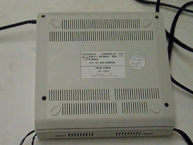
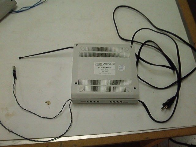
Model AD905WT/22 14V 130mA 864MHz Serial number Manufactured Made in China transmitter label EUROPE black box label EUROPE Pz1 + s 0682 ! Model AD905WA/22 230V 864MHz Serial number Manufactured Made in China Pz1 + s 0682 ! 50Hz 20W Model AD905WT/25 14V 130mA 864MHz Serial number Manufactured Made in China transmitter label UK black box label UK 0682 ! Model AD905WA/25 230V 864MHz Serial number Manufactured Made in China 0682 ! 50Hz 20W LISTED AUDIO EQUIPMENT 22F8 EQUIPEMENT AUDIO Model AD905WT/37 14V 130mA 914MHz FCC ID: BOU AD905W CAN Serial number Manufactured c The device complies with part 15 of the FCC Rules. Operation is subject to the following two conditions: (1) this device may not cause harmful interference and (2) this device must accept any interference received including interference that may cause undesired operation. Philips Consumer Electronics Company, Knoxville, Tennessee 37914 - 1810 U.S.A. Made in China transmitter label USA LISTED AUDIO EQUIPMENT 22F8 EQUIPEMENT AUDIO Model AD905WA/37 120V 914MHz FCC ID: BOU AD905W CAN Serial number Manufactured c The device complies with part 15 of the FCC Rules. Operation is subject to the following two conditions: (1) this device may not cause harmful interference and (2) this device must accept any interference received including interference that may cause undesired operation. Philips Consumer Electronics Company, Knoxville, Tennessee 37914 - 1810 U.S.A. Made in China black box label USA 50-60Hz 20W
ID Label/Location Info
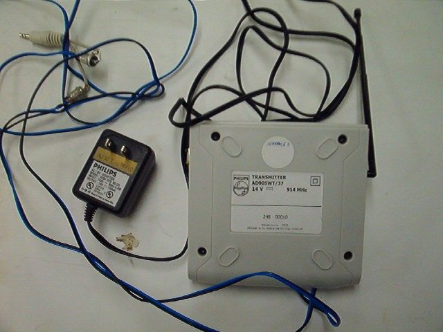
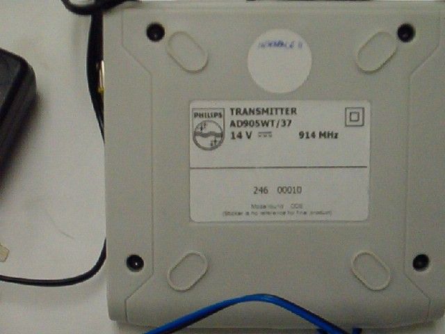
PHILIPS TESTING SERVICE Our Commitment To Excellence Is Total Customer Satisfaction A Division of Philips Consumer Electronics Mainstream One Philips Drive P.O. Box 14810 Knoxville, TN 37914-1810 Tel: (865) 521-1630 The model number label is located on the bottom of the Transmitter as pictured here. Philips Wireless Speaker Transmitter Model AD905WT/37 FCC ID: BOU AD905W
Operational Description
1. GENERAL The Mark-3 transmitter is designed specifically for use with a TV set as a surround signal (Digital Dolby or ProLogic) transmitter towards wireless surround speakers. As such the transmitter can be connected via a cable assy. towards the TV set. Audio, supply and I²C signals can be extracted out of the TV chassis. The transmitter is designed for high quality stereo audio from 20Hz to 20kHz and has a compander to enable high S/N ratios. The basic version is intended for the European freq. band of 863-865 MHz. Derived versons are available for 433 and 914 MHz. The pilot and subcarrier frequency have been set to 23.4375 kHz and 46.875 kHz. (3th harmonic related to 15.625 kHz). This way interference whistling in TV sets with 15625 Hz is avoided. Further the translitter has improved pulling behaviour which results in additional immunity to picking up stray EM-fields from the TV hardware. The Mark-3 module needs proper I²C signals from the host controller at hex C6 to properly set the synthesiser and other functions on board of the Tx. For details on I 2 C commands to send refer to our document " I 2 C commands for Mark-3 Transmitter" archived under 3104 217 07110 sheet 112. 2. USED TECHNOLOGIES AND DIMENSIONS The design platform is MentorGraphics with CE design rules acc. UAND1829 & UAND1833. The pb technology used is class 5 on FR4 1.6mm thickness, 2 layers Component management system : LSDB Archiving system : PALS / CORDIS Stuffing technologies : SMD in 0603/0805 size and SMD elcaps manual for some remaining components The pb is set up as 1/6 of a 141 by 240 mm workboard . The exact dimensioning is 80mm by 62.5mm per unit. See last sheet for sketch drawing. 3. INPUTS / OUTPUTS The connectable transmitter has to be connected to the driving set by a shielded 8 fold flatcable . Connector type at transmitter side : 8-fold jst type EH vertical Wire function Jst on pcb , pin no R input 1 Signal ground 2 L input 3 Supply input +12V 4 Power ground + shield wire 5 Power ground 6 SCL of I2C 7 SDA of I2C 8 Note : drain wire of shield connected to pin 5 (as wiring of MG98 cable) Input sensitivity for max deviation (50 kHz) : 0.42 Vrms Input impedance : typ. 12 kohm Driving impedance (from TV source) : < 100 ohm 3XX000 0 2002-02-04 1 0 2002-02-22 2 0 2002-03-05 3 Mark 3 Wireless Transmitter version 0.3 3104 217 0711 Name: Felix Elsen PDSL_L 5 190 - 1 10 A4 PL Or. date 2002-01-12 Koninklijk PHILIPS Electronics N.V. All rights reserved 4. FEATURING The following main features are installed : -no spurious RF power output when applying DC power to the Mark-3 module. -pilot mute possibility to mute the speaker remotely -pilot mute at power-down (TV set switch off or mains cord pull) -on board printed aerial that supports 864 and 926 MHz . There is a backup solution with a telescopic aerial (17cm) for 433 MHz versions. (all vertical polarisation) -build in audio limiter to limit the emitted RF bandwidth to the ETSI requirements . - 4 RF channels avilable on a 400 kHz grid (all versions) -the local osc. and power amplifier can be switched off by I²C commands. -a mono-stereo switch to switch out the DSB spectrum around the subcarrier freq. -improved load-pull behaviour Note : -the host microcontroller needs to send detailed I²C commands to the module because there is no local uP on board for cost saving reasons. For full details on I²C codes to send refer to the Software interface manual sheet 112 of 3104 217 07110. -there is no audio trigger circuit foreseen in the basic module for BGTV application because the competent body considers the 5min timeout period in the ETSI EN 301 357-1 requirements to be fulfilled when the TV is switched to standby or to off. 5. ENVIRONMENTAL AND EMC The design meets the technical and legal requirements for the different frequency band executions : -EN 301 357 : Technical requirements for wireless audio at 25 MHz – 2GHz. -EN 301 489-9 : EMC for cordless audio and radiomicrophones -FCC part 15 , subpart C (US 926 MHz version) -Safety requirements : acc. CE and BGTV requirements. 6. USED KEY COMPONENTS -compander function : SA572D (Philips) and NJM4565M (JRC) -pilot / subcarrier generator 74HC4060D / 74HC00 (Philips) -MPX filter : NJM 4565M (JRC) -synthesiser TSA5060ATS (Philips) 7. FREQUENCY AND CHANNEL INFORMATION The frequency allocations differ from the previous wireless families. Channel no 864 MHz 914 MHz 433 MHz 1 863.300 914.100 433.300 2 863.700 914.500 433.700 3 864.100 914.900 434.100 4 864.500 915.300 434.500 3XX000 0 2002-02-04 1 0 2002-02-22 2 0 2002-03-05 3 Mark 3 Wireless Transmitter version 0.3 3104 217 0711 Name: Felix Elsen PDSL_L 5 190 - 2 10 A4 PL Or. date 2002-01-12 Koninklijk PHILIPS Electronics N.V. All rights reserved 8. BLOCKDIAGRAM OF THE MARK-3 TRANSMITTER 3XX000 0 2002-02-04 1 0 2002-02-22 2 0 2002-03-05 3 Mark 3 Wireless Transmitter version 0.3 3104 217 0711 Left in data clock Right in 12V supply synthesiser TSA5060 osc com pan der PA osc 12 MHz switch sum amp +filter amp + filter square to sine stereo coder supply powerdown P0 : stereo-mono P1 : PA enable P3 : LO enable P2 : pilot disable 46.875 kHz subcar 23.4375 kHz pilot multiplexed MPX dc loop voltage PD I2C address select version select ASADC drive subc pil x2 Name: Felix Elsen PDSL_L 5 190 - 3 10 A4 PL Or. date 2002-01-12 Koninklijk PHILIPS Electronics N.V. All rights reserved 9. SPECIFICATIONS -specs are valid on all 4 channels. -Full signal to noise measurements must be done with the accompanying Mark-3 receiver, equipped with an expander circuit Common specification points Subject Minimum Typical Maximum Power supply voltage range -15% 12.0 V +10% Supply current at typical voltage - 110 mA 120 mA Power supply ripple rejection (50-300Hz) 65 dB 75 dB - Nominal modulation deviation at nom input 45 kHz 50 kHz 55 kHz Nominal AF input (L&R) for 50 kHz dev 0.41 Vrms Loading at input I2C bus (data/clock) without cable With standard cable length tbf pF tbf pF I²C address C6 (hex) Spec…
Text truncated - open the document above for the full version.
Test Report
RADIATED EMISSIONS Equipment Used During Testing Cal Due Device Model S/N Date Date Spectrum Analyzer HP 8566B 6612 7/22/02 7/22/03 Quasi-Peak Adapter HP 85650A 1850 7/17/02 7/17/03 RF Pre-selector HP 85685A 0627 9/24/02 9/24/03 Bicon Antenna EMCO 3110 1679 9/9/02 9/9/03 Log-Periodic Antenna EMCO 3146 1549 9/8/02 9/8/03 Horn Antenna EMCO 3115 3459 12/8/02 12/8/03 CONDUCTED EMISSIONS Equipment Used During Testing Cal Due Device Model S/N Date Date Spectrum Analyzer HP 8566B 3915 8/30/02 8/30/03 Quasi-Peak Adapter HP 85650A 1001 7/29/02 7/29/03 RF Pre-selector HP 85685A 0595 9/25/02 9/25/03 LISN Fischer 50/250 6 & 7 10/15/02 10/15/03 PHILIPS TESTING SERVICE Our Commitment To Excellence Is Total Customer Satisfaction A Division of Philips Consumer Electronics Mainstream One Philips Drive P.O. Box 14810 Knoxville, TN 37914-1810 Tel: (865) 521-1630 APPLICANT: Philips Consumer Electronics Company FCC ID: BOU AD905W MEASUREMENTS REPORT ( EUT on Channel #1 of 4 ) NAME OF TEST : THREE METER OPEN FIELD RADIATED EMMISSIONS FCC RULES: PART 15.249 Operation in the 902 – 928 Mhz Band MEASUREMENT DISTANCE: 3 – METERS EUT Height above Ground Plain : 80 cm REQUIREMENTS: Fundamental Frequency Fundamental Freq. MAX Field strength Harmonic MAX Field strength ( MHZ ) (dBuv/meter) (dBuv/meter) 914.1 94 dBuv/meter 54 dBuv/meter TEST DATA: Emission Meter Antenna correction (antenna+cable) Field Frequency Reading Polarity factor Strength (MHZ) (dBuv) (dB) (dBuv/meter) 914.12 65.7 V 28.2 93.9 1828.24 15.2 H 37.1 52.3 2742.36 10.9 V 42.1 53.0 3656.48 7.2 V 46.1 53.3 • Measurements were conducted from 30 Mhz to 10 Ghz and only those frequencies reported above were detectable on the 3-meter test site. • Measurements reported below 1 Ghz are reported as Quasi Peak Measurements. (RBW=100Khz and VBW 100Khz) • Measurements reported above 1 Ghz are reported as Average measurements. (RBW=1Mhz) • Measurements were made in accordance with ANSI C63.4 –2000 (section # 13) • RF Spectrum Analyzer used was HP8566B w/ QP Adapter HP85650 • TEST RESULTS: The transmitter does meet FCC Part 15.249 and IC RSS-210 requirements. TESTED BY: Steve Vann TEST DATE: 2/11/2003 Tested at the Philips Consumer Electronics Company test facility located in Knoxville, Tennessee. PHILIPS TESTING SERVICE Our Commitment To Excellence Is Total Customer Satisfaction A Division of Philips Consumer Electronics Mainstream One Philips Drive P.O. Box 14810 Knoxville, TN 37914-1810 Tel: (865) 521-1630 APPLICANT: Philips Consumer Electronics Company FCC ID: BOU AD905W MEASUREMENTS REPORT ( EUT on Channel # 2 of 4 ) NAME OF TEST : THREE METER OPEN FIELD RADIATED EMMISSIONS FCC RULES: PART 15.249 Operation in the 902 – 928 Mhz Band MEASUREMENT DISTANCE: 3 - METERS EUT Height above Ground Plain : 80 cm REQUIREMENTS: Fundamental Frequency Fundamental Freq. MAX Field strength Harmonic MAX Field strength ( MHZ ) (dBuv/meter) (dBuv/meter) 914.54 94 dBuv/meter 54 dBuv/meter TEST DATA: Emission Meter Antenna correction (antenna+cable) Field Frequency Reading Polarity factor Strength (MHZ) (dBuv) (dB) (dBuv/meter) 914.54 65.6 V 28.3 93.9 1829.08 15.0 H 37.1 52.1 2743.62 11.1 V 42.1 53.2 3658.16 7.1 V 46.1 53.2 • Measurements were conducted from 30 Mhz to 10 Ghz and only those frequencies reported above were detectable on the 3-meter test site. • Measurements reported below 1 Ghz are reported as Quasi Peak Measurements. (RBW=100Khz and VBW 100Khz) • Measurements reported above 1 Ghz are reported as Average measurements. (RBW=1Mhz) • Measurements were made in accordance with ANSI C63.4 –2000 (section # 13) • RF Spectrum Analyzer used was HP8566B w/ QP Adapter HP85650 TEST RESULTS: The transmitter does meet FCC Part 15.249 and IC RSS-210 requirements. TESTED BY: Steve Vann TEST DATE: 2/11/2003 Tested at the Philips Consumer Electronics Company test facility located in Knoxville, Tennessee. PHILIPS TESTING SERVICE Our Commitment To Excellence Is Total Customer Satisfaction A Division of Philips Consumer Electronics Mainstream One Philips Drive P.O. Box 14810 Knoxville, TN 37914-1810 Tel: (865) 521-1630 APPLICANT: Philips Consumer Electronics Company FCC ID: BOU AD905W MEASUREMENTS REPORT ( EUT on Channel # 3 of 4 ) NAME OF TEST : THREE METER OPEN FIELD RADIATED EMMISSIONS FCC RULES: PART 15.249 Operation in the 902 – 928 Mhz Band MEASUREMENT DISTANCE: 3 - METERS EUT Height above Ground Plain : 80 cm REQUIREMENTS: Fundamental Frequency Fundamental Freq. MAX Field strength Harmonic MAX Field strength ( MHZ ) (dBuv/meter) (dBuv/meter) 914.92 94 dBuv/meter 54 dBuv/meter TEST DATA: Emission Meter Antenna correction (antenna+cable) Field Frequency Reading Polarity factor Strength (MHZ) (dBuv) (dB) (dBuv/meter) 914.92 65.4 V 28.3 93.7 1829.84 15.7 H 37.1 52.8 2744.76 11.2 H 42.1 53.3 3659.68 7.1 V 46.1 53.2 • Measurements were conducted from 30 Mhz to 10 Ghz and only those frequencies reported above were detectable on the 3-meter test site. • Measurements reported below 1 Ghz are reported as Quasi Peak Measurements. (RBW=100Khz and VBW 100Khz) • Measurements reported above 1 Ghz are reported as Average measurements. (RBW=1Mhz) • Measurements were made in accordance with ANSI C63.4 –2000 (section # 13) • RF Spectrum Analyzer used was HP8566B w/ QP Adapter HP85650 TEST RESULTS: The transmitter does meet FCC Part 15.249 and IC RSS-210 requirements. TESTED BY: Steve Vann TEST DATE: 2/11/2003 Tested at the Philips Consumer Electronics Company test facility located in Knoxville, Tennessee. PHILIPS TESTING SERVICE Our Commitment To Excellence Is Total Customer Satisfaction A Division of Philips Consumer Electronics Mainstream One Philips Drive P.O. Box 14810 Knoxville, TN 37914-1810 Tel: (865) 521-1630 APPLICANT: Philips Consumer Electronics Company FCC ID: BOU AD905W MEASUREMENTS REPORT ( EUT on Channel # 4 of 4 ) NAME OF TEST : THREE METER OPEN FIELD RADIATED EMMISSIONS FCC RULES: PART 15.249 Operation in the 902 – 928 Mhz Band MEASUREMENT DISTANCE: 3 - METERS EUT Height above Ground P…
Text truncated - open the document above for the full version.
Contact Information
Applicant
Tee Wee Jaw(Director, Project Management)
Test Firm
Global Testing Laboratory, LLCCaile Gonzalez
Technical Specifications
| # | Rule Parts | Frequency Range | Power Output |
|---|---|---|---|
| 1 | 15C | 914.1 MHz - 915.3 MHz | - |
Other Applications from Philips Consumer Lifestyle
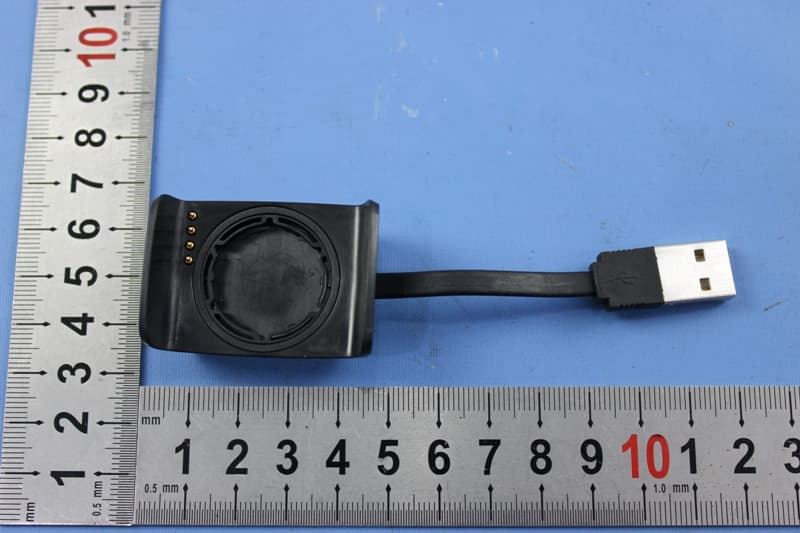
BOUDL8775
May 21, 2015BLE Activity Monitor with OHR
Equipment Class
DTS - Digital Transmission System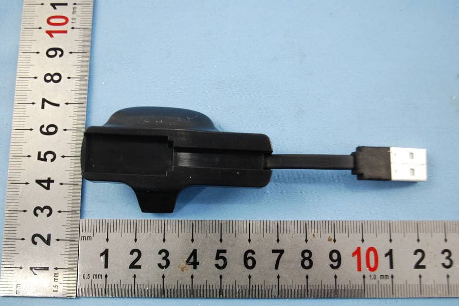
BOUDL8770
Sep 17, 2014Activity Monitor with OHR
Equipment Class
JBP - Part 15 Class B Computing Device Peripheral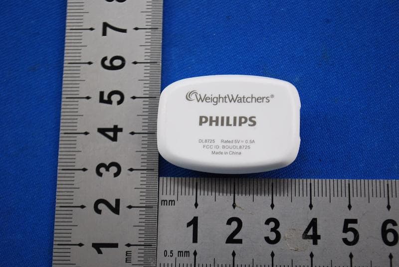
BOUDL8725
Jul 10, 2014Personal Activity Monitor with Bluetooth Function
Equipment Class
JBP - Part 15 Class B Computing Device Peripheral
BOUSCD501
May 28, 20141.9GHz DECT Baby Monitor - Baby Unit
Equipment Class
PUB - Part 15 Unlicensed PCS Base Station
BOUSCD501H
May 28, 20141.9GHz DECT Baby Monitor - Parent Unit
Equipment Class
PUT - Part 15 Unlicensed PCS portable Tx worn on body