BOUSCD5251.9GHz BABY MONITOR - BABY UNIT
Philips Consumer Lifestyle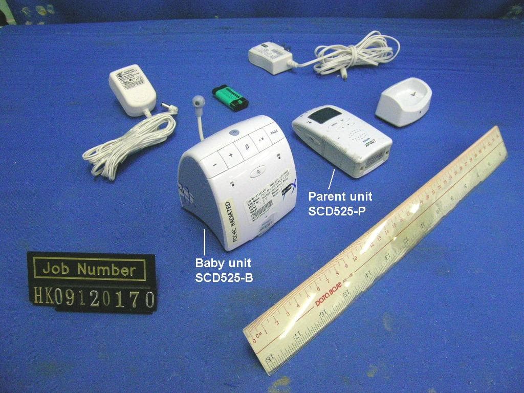
Click to zoom
Application Details
- Equipment Class
- PUB - Part 15 Unlicensed PCS Base Station
- Date of Grant
- Apr 15, 2010
- Application Purpose
- Original Equipment
- Date of Application
- Apr 14, 2010
- Equipment Note
- 1.9GHz BABY MONITOR - BABY UNIT
- Frequency Range
- 1921.53600000 - 1928.44800000
- Company
- Philips Consumer Lifestyle
- Country
- Hong Kong
Documents & Files
Document Text
Text extracted from the exhibit documents filed with the FCC. Open a document above to read the original.
Users Manual
SCD525 4222.005.0010.1.indd 131-03-10 14:29 2 4222.005.0010.1.indd 231-03-10 14:29 3 1 2 5 3 4 6 8 7 15 16 9 7 10 1 2 3 4 5 6 9 12 20 13 19 17 11 12 11 8 18 14 1 5 4 7 6 3 2 22 10 15 16 17 21 13 14 3 4222.005.0010.1.indd 331-03-10 14:29 4 4222.005.0010.1.indd 431-03-10 14:29 SCD525 EngliSh 6 FrançaiS (CanaDa) 22 SpaniSh 41 4222.005.0010.1.indd 531-03-10 14:29 6 iMpOr TanT SaFETY inSTr UCTiOnS Some of the following information may not apply to your particular product; however, when using baby monitor equipment, basic safety precautions should always be followed to reduce the risk of fire, electric shock and injury to persons, including the following: 1 Read these instructions. 2 Keep these instructions. 3 Heed all warnings. 4 Follow all instructions. 5 Do not use this apparatus near water. 6 Clean only with dry cloth. 7 Do not block any ventilation openings. Install in accordance with the manufacturer’s instructions. 8 Do not install near any heat sources such as radiators, heat registers, stoves or other apparatus (including amplifiers) that produce heat. 9 Do not defeat the safety purpose of the polarized or grounding-type plug. A polarized plug has two blades with one wider than the other. A grounding-type plug has two blades and a third grounding prong. The wide blade or the third prong are provided for your safety. If the provided plug does not fit into your outlet, consult an electrician for replacement of the obsolete outlet. 10 Protect the power cord from being walked on or pinched particularly at plugs, convenience receptacles, and the point where they exit from the apparatus. 11 Only use attachments/accessories specified by the manufacturer. 12 Unplug this appliance during lightning storms or when not used for long periods of time. 13 Refer all servicing to qualified service personnel. Servicing is required when the apparatus has been damaged in any way, such as power-supply cord or plug is damaged, liquid has been spilled or objects have fallen into the apparatus, the apparatus has been exposed to rain or moisture, does not operate normally, or has been dropped. For assistance visit our website www.philips. com/AVENT or call 1-800-54-AVENT (1-800-542-8368). 14 This baby monitor is intended as an aid. It is not a substitute for responsible and proper adult supervision and should not be used as such. 15 Use this appliance only for its intended use as described in this manual. 16 Unplug this product from the wall outlet before cleaning. Do not use liquid cleaners or aerosol cleaners. 17 Products should not be used while you are in a bathtub, shower or pool. Immersion of the product in water could cause an electrical shock. 18 This product should be operated only from the type of power source indicated on the type plate of the adapters (A13,B10). If you are not sure of the type of power supply to your home, consult your dealer or local power company. 19 The apparatus shall not be exposed to dripping or splashing and no objects filled with liquids, such as vases, shall be placed on the apparatus. 20 Do not overload wall outlets and extension cords as this can result in the risk of fire or electric shock. 21 Never push objects of any kind into this product through casing slots as they may touch dangerous voltage points or short out parts that could result in a risk of fire or electric shock. Never spill liquid of any kind on the product. 22 To reduce the risk of electric shock, do not disassemble this product, but visit our website www. philips.com/AVENT or call 1-800-54-AVENT (1-800-542-8368) for assistance. Opening or removing covers (except battery compartment lids) may expose you to dangerous voltage or other risks. Incorrect reassembly can cause electric shock when the appliance is subsequently used. EngliSh 4222.005.0010.1.indd 631-03-10 14:29 23 To prevent strangulation with power cord, never place monitor within reach of child. Do not use with extension cords. 24 Do not place any sources of danger on the apparatus (like liquid-filled objects, lighted candles etc.). if your product utilizes batteries, the following additional precautions should be observed: 1 Use only the type and size of batteries specified in the user manual. 2 Do not dispose of batteries in fire. They may explode. Check with local regulations for possible special disposal instructions. 3 Exercise care in handling batteries in order not to short out the batteries with conducting materials such as rings, bracelets and keys. Overcharging, short circuiting, reverse charging, mutilation, or incineration of batteries must be avoided to prevent one or more of the following occurrences: release of toxic materials, release of hydrogen and/or oxygen gas, rise in surface temperature. 4 Do not attempt to recharge batteries provided with or identified for use with this product that are not intended to be charged. The batteries may leak corrosive electrolyte or explode. 5 Do not attempt to rejuvenate the batteries provided with or identified for use with this product by heating them. Sudden release of battery electrolyte may occur, causing burns or irritation to eyes or skin. 6 If and when necessary, the batteries must be replaced with identical new ones from the same manufacturer. If a battery to be replaced is connected with other batteries in series, it is recommended that the other batteries be replaced with new ones at the same time. 7 Reverse polarity installation of the batteries in the end product must be avoided. Reverse insertion of batteries can cause charging, and that may result in leakage or explosion. 8 Remove batteries from this product if you store the product over 30 days because the batteries could leak and damage the product. 9 Discard ‘dead’ batteries as soon as possible since ‘dead’ batteries are more likely to leak in a product. If a battery has leaked or vented, it should be replaced immediately using protective gloves. 10 Do not store this product, or the batteries provided with or identified for…
Text truncated - open the document above for the full version.
Cover Letter(s)
[BOUSCD525_circuit.pdf, BOUSCD525H_circuit.pdf] [BOUSCD525_block.pdf, BOUSCD525H_block.pdf] [BOUSCD525_descri.pdf, BOUSCD525H_descri.pdf]
External Photos
INTERTEK TESTING SERVICES External Photos FCC ID: BOUSCD525 IC: 135M-SCD525external photos - 1 of 2 INTERTEK TESTING SERVICES External Photos FCC ID: BOUSCD525 IC: 135M-SCD525external photos - 2 of 2
ID Label/Location Info
SCD525US CSA LABEL(Update on Jan 25,10) HS LABEL SIZE:27L*12Hmm SCD525-C MADE IN CHINA CHG LABEL SIZE:21L*12Hmm Color:Light Grey/Black Color:Light Grey/Black BS LABEL SIZE:16L*11Hmm Color:Purple cloud/Black SCD525-P FCC ID : BOUSCD525H IC : 135M-SCD525H MADE IN CHINA SCD525-B FCC ID : BOUSCD525 IC : 135M-SCD525 MADE IN CHINA BS LABEL SIZE:18L*12Hmm Color:White/Black SCD525-B/SCD525-P Label location Baby unit Parent unit SCD510E US CSA LABEL(Update on Jan 25,10) HS LABEL SIZE:27L*12Hmm CSA LABEL SIZE:16L*11Hmm Color:Purple cloud/Black Color:Purple cloud/Black SCD510-P FCC ID : BOUSCD525H IC : 135M-SCD525H MADE IN CHINA SCD510-B FCC ID : BOUSCD525 IC : 135M-SCD525 MADE IN CHINA BS LABEL SIZE:18L*12Hmm Color:White/Black 92-012655-010-100 SCD510-B/SCD510-P Label location Baby unit Parent unit
Internal Photos
INTERTEK TESTING SERVICES Internal photos - Model: SCD525-B FCC ID: BOUSCD525 IC: 135M-SCD525internal photos - 1 of 14 Baby Unit assembly (View 1) Baby Unit assembly (View 2) INTERTEK TESTING SERVICES Internal photos - Model: SCD525-B FCC ID: BOUSCD525 IC: 135M-SCD525internal photos - 2 of 14 Baby Unit Speaker PCB Baby Unit Main PCB comp side (View 1) INTERTEK TESTING SERVICES Internal photos - Model: SCD525-B FCC ID: BOUSCD525 IC: 135M-SCD525internal photos - 3 of 14 Baby Unit Main PCB comp side (View 2) Baby Unit Main PCB solder side INTERTEK TESTING SERVICES Internal photos - Model: SCD525-B FCC ID: BOUSCD525 IC: 135M-SCD525internal photos - 4 of 14 Baby Unit Power Supply PCB front side Baby Unit Power Supply PCB rear side INTERTEK TESTING SERVICES Internal photos - Model: SCD525-B FCC ID: BOUSCD525 IC: 135M-SCD525internal photos - 5 of 14 Baby Unit Battery Contact PCB front side Baby Unit Battery Contact PCB rear side INTERTEK TESTING SERVICES Internal photos - Model: SCD525-B FCC ID: BOUSCD525 IC: 135M-SCD525internal photos - 6 of 14 Baby Unit Power Button PCB front side Baby Unit Power Button PCB rear side INTERTEK TESTING SERVICES Internal photos - Model: SCD525-B FCC ID: BOUSCD525 IC: 135M-SCD525internal photos - 7 of 14 Baby Unit DECT RF Module comp side Baby Unit DECT RF Module solder side INTERTEK TESTING SERVICES Internal photos - Model: SCD510-B FCC ID: BOUSCD525 IC: 135M-SCD525internal photos - 8 of 14 Baby Unit assembly Baby Unit Speaker PCB INTERTEK TESTING SERVICES Internal photos - Model: SCD510-B FCC ID: BOUSCD525 IC: 135M-SCD525internal photos - 9 of 14 Baby Unit Main PCB comp side (View 1) Baby Unit Main PCB comp side (View 2) INTERTEK TESTING SERVICES Internal photos - Model: SCD510-B FCC ID: BOUSCD525 IC: 135M-SCD525internal photos - 10 of 14 Baby Unit Main PCB comp side (View 3) Baby Unit Main PCB solder side INTERTEK TESTING SERVICES Internal photos - Model: SCD510-B FCC ID: BOUSCD525 IC: 135M-SCD525internal photos - 11 of 14 Baby Unit Power Supply PCB front side Baby Unit Power Supply PCB rear side INTERTEK TESTING SERVICES Internal photos - Model: SCD510-B FCC ID: BOUSCD525 IC: 135M-SCD525internal photos - 12 of 14 Baby Unit Battery Contact PCB front side Baby Unit Battery Contact PCB rear side INTERTEK TESTING SERVICES Internal photos - Model: SCD510-B FCC ID: BOUSCD525 IC: 135M-SCD525internal photos - 13 of 14 Baby Unit Power Button PCB front side Baby Unit Power Button PCB rear side INTERTEK TESTING SERVICES Internal photos - Model: SCD510-B FCC ID: BOUSCD525 IC: 135M-SCD525internal photos - 14 of 14 Baby Unit DECT RF Module comp side Baby Unit DECT RF Module solder side
RF Exposure Info
INTERTEK TESTING SERVICES FCC ID: BOUSCD525 RF exposure - 1 of 2 For Maximum Permissible Exposure (MPE) evaluation of the baby unit, the maximum power density at 20 cm from this mobile transmitter shall be less than the General Population / Uncontrolled MPE limit in OET Bulletin 65. For the baby unit of tested model of SCD525-B, the maximum field strength measured (FS) was 118.2 dBμV/m. The distance (D) between the antenna and the equipment under test (EUT) was 3 meters. And the maximum source-based time- averaging duty factor in talking with one parent unit is 8.33%. From these data, the exposed power density at a distance (R) of 20cm from the center of radiation of the antenna can be calculated according to OET Bulletin 65 as follow: The radiated power = (FS*D) 2 / 30 = 198.21 mW The radiated (EIRP) source-based time-averaging output power = (198.21 * 0.083) mW = 16.51 mW The power density at 20 cm from the antenna = EIRP / 4πR 2 = 0.0033 mW cm -2 In the frequency range of 1,500 - 100,000MHz, the MPE limit is 1.0 mWcm -2 for general population and uncontrolled exposure. As the measured power density at 20cm from the transmitter is lower than the MPE limit, the compliance to the MPE limit can be ensured by indicating the minimum 20cm separation between the transmitter's radiating structures and body of the user or nearby persons. The following RF exposure statement is proposed to be included in the user manual: “ FCC RF Radiation Exposure Statement Caution: To maintain compliance with the FCC’s RF exposure guidelines, place the baby unit at least 20cm from nearby persons.” INTERTEK TESTING SERVICES FCC ID: BOUSCD525 RF exposure - 2 of 2 For Maximum Permissible Exposure (MPE) evaluation of the baby unit, the maximum power density at 20 cm from this mobile transmitter shall be less than the General Population / Uncontrolled MPE limit in OET Bulletin 65. For the baby unit of tested model of SCD510-B, the maximum field strength measured (FS) was 115.4 dBμV/m. The distance (D) between the antenna and the equipment under test (EUT) was 3 meters. And the maximum source-based time- averaging duty factor in talking with one parent unit is 8.33%. From these data, the exposed power density at a distance (R) of 20cm from the center of radiation of the antenna can be calculated according to OET Bulletin 65 as follow: The radiated power = (FS*D) 2 / 30 = 104.02 mW The radiated (EIRP) source-based time-averaging output power = (104.02 * 0.083) mW = 8.66 mW The power density at 20 cm from the antenna = EIRP / 4πR 2 = 0.0017 mW cm -2 In the frequency range of 1,500 - 100,000MHz, the MPE limit is 1.0 mWcm -2 for general population and uncontrolled exposure. As the measured power density at 20cm from the transmitter is lower than the MPE limit, the compliance to the MPE limit can be ensured by indicating the minimum 20cm separation between the transmitter's radiating structures and body of the user or nearby persons. The following RF exposure statement is proposed to be included in the user manual: “ FCC RF Radiation Exposure Statement Caution: To maintain compliance with the FCC’s RF exposure guidelines, place the baby unit at least 20cm from nearby persons.”
Test Report
Report no.: HK09120170-1 Model no.: SCD525-B Talk Mode w/charging w/lamp & Lullaby Playback AC Mains “L” Ctrl No.: N/A PAGE 1 Report No.:HK09120170-1 Scan Settings (1 Range) |--------- Frequencies -----------||----------- Receiver Settings ------------| Start Stop Step IF BW Detector M-Time Atten Preamp OpRge 150k 30M 4.5k 10k PK+AV 10ms AUTO LN OFF 60dB Final Measurement: x QP / + AV Meas Time: 1 s Subranges: 16 Acc Margin: 20dB Transducer No. Start Stop Name 1 1 9k 30M 2454 2 9k 30M 0700 3 9k 30M 0090 0 10 20 30 40 50 60 70 80 90 dBuV 100 0.15 MHz 30 110 F15Q F15A Report no.: HK09120170-1 Model no.: SCD525-B Talk Mode w/charging w/lamp & Lullaby Playback AC Mains “L” Ctrl No.: N/A Report No.:HK09120170-1 Scan Settings (1 Range) |--------- Frequencies -----------||----------- Receiver Settings ------------| Start Stop Step IF BW Detector M-Time Atten Preamp OpRge 150k 30M 4.5k 10k PK+AV 10ms AUTO LN OFF 60dB Final Measurement Results: Frequency QP Level QP Limit Delta MHz dB dB dB no Results Frequency AV Level AV Limit Delta MHz dB dB dB 0.31200 35.8 49.9 -14.1 * limit exceeded Report no.: HK09120170-1 Model no.: SCD525-B Talk Mode w/charging w/lamp & Lullaby Playback AC Mains “N” Ctrl No.: N/A PAGE 1 Report No.:HK09120170-1 Scan Settings (1 Range) |--------- Frequencies -----------||----------- Receiver Settings ------------| Start Stop Step IF BW Detector M-Time Atten Preamp OpRge 150k 30M 4.5k 10k PK+AV 10ms AUTO LN OFF 60dB Final Measurement: x QP / + AV Meas Time: 1 s Subranges: 16 Acc Margin: 20dB Transducer No. Start Stop Name 1 1 9k 30M 2454 2 9k 30M 0700 3 9k 30M 0090 0 10 20 30 40 50 60 70 80 90 dBuV 100 0.15 MHz 30 110 F15Q F15A Report no.: HK09120170-1 Model no.: SCD525-B Talk Mode w/charging w/lamp & Lullaby Playback AC Mains “N” Ctrl No.: N/A Report No.:HK09120170-1 Scan Settings (1 Range) |--------- Frequencies -----------||----------- Receiver Settings ------------| Start Stop Step IF BW Detector M-Time Atten Preamp OpRge 150k 30M 4.5k 10k PK+AV 10ms AUTO LN OFF 60dB Final Measurement Results: Frequency QP Level QP Limit Delta MHz dBuV dBuV dB 1.61250 30.1 56.0 -25.9 Frequency AV Level AV Limit Delta MHz dBuV dBuV dB 0.30750 30.2 50.0 -19.8 * limit exceeded Report no.: HK09120170-1 Model no.: SCD510-B Talk Mode w/charging w/lamp AC Mains “L” Ctrl No.: N/A PAGE 1 Report No.:HK09120170-1 Scan Settings (1 Range) |--------- Frequencies -----------||----------- Receiver Settings ------------| Start Stop Step IF BW Detector M-Time Atten Preamp OpRge 150k 30M 4.5k 10k PK+AV 10ms AUTO LN OFF 60dB Final Measurement: x QP / + AV Meas Time: 1 s Subranges: 16 Acc Margin: 20dB Transducer No. Start Stop Name 1 1 9k 30M 2454 2 9k 30M 0700 3 9k 30M 0090 0 10 20 30 40 50 60 70 80 90 dBuV 100 0.15 MHz 30 110 F15Q F15A Report no.: HK09120170-1 Model no.: SCD510-B Talk Mode w/charging w/lamp AC Mains “L” Ctrl No.: N/A Report No.:HK09120170-1 Scan Settings (1 Range) |--------- Frequencies -----------||----------- Receiver Settings ------------| Start Stop Step IF BW Detector M-Time Atten Preamp OpRge 150k 30M 4.5k 10k PK+AV 10ms AUTO LN OFF 60dB Final Measurement Results: Frequency QP Level QP Limit Delta MHz dBuV dBuV dB 1.54500 23.3 56.0 -32.7 Frequency AV Level AV Limit Delta MHz dBuV dBuV dB no Results * limit exceed Report no.: HK09120170-1 Model no.: SCD510-B Talk Mode w/charging w/lamp AC Mains “N” Ctrl No.: N/A PAGE 1 Report No.:HK09120170-1 Scan Settings (1 Range) |--------- Frequencies -----------||----------- Receiver Settings ------------| Start Stop Step IF BW Detector M-Time Atten Preamp OpRge 150k 30M 4.5k 10k PK+AV 10ms AUTO LN OFF 60dB Final Measurement: x QP / + AV Meas Time: 1 s Subranges: 16 Acc Margin: 20dB Transducer No. Start Stop Name 1 1 9k 30M 2454 2 9k 30M 0700 3 9k 30M 0090 0 10 20 30 40 50 60 70 80 90 dBuV 100 0.15 MHz 30 110 F15Q F15A Report no.: HK09120170-1 Model no.: SCD510-B Talk Mode w/charging w/lamp AC Mains “N” Ctrl No.: N/A Report No.:HK09120170-1 Scan Settings (1 Range) |--------- Frequencies -----------||----------- Receiver Settings ------------| Start Stop Step IF BW Detector M-Time Atten Preamp OpRge 150k 30M 4.5k 10k PK+AV 10ms AUTO LN OFF 60dB Final Measurement Results: no Results
Test Report
INTERTEK TESTING SERVICES Unwanted Emission Inside The Sub-Band Plots FCC ID: BOUSCD525 inband - 1 of 2 A0 Baby unit, Lowest channel, Traffic carrier Baby unit, Highest channel, Traffic carrier INTERTEK TESTING SERVICES Unwanted Emission Inside The Sub-Band Plots FCC ID: BOUSCD525 inband - 2 of 2 A0 Baby unit, Lowest channel, Dummy carrier Baby unit, Highest channel, Dummy carrier
Test Report
INTERTEK TESTING SERVICES Peak Transmit Power Plots FCC: BOUSCD525 IC: 135M-SCD525 peaktp - 1 of 3 A0 Baby unit, Lowest channel, Traffic carrier Baby unit, Middle channel, Traffic carrier INTERTEK TESTING SERVICES Peak Transmit Power Plots FCC: BOUSCD525 IC: 135M-SCD525 peaktp - 2 of 3 A0 Baby unit, Highest channel, Traffic carrier Baby unit, Lowest channel, Dummy carrier INTERTEK TESTING SERVICES Peak Transmit Power Plots FCC: BOUSCD525 IC: 135M-SCD525 peaktp - 3 of 3 A0 Baby unit, Middle channel, Dummy carrier Baby unit, Highest channel, Dummy carrier
Test Report
INTERTEK TESTING SERVICES Power Spectral Density Plots FCC ID: BOUSCD525 psd - 1 of 2 A0 Baby unit, Lowest channel, Traffic carrier Baby unit, Highest channel, Traffic carrier INTERTEK TESTING SERVICES Power Spectral Density Plots FCC ID: BOUSCD525 psd - 2 of 2 A0 Baby unit, Lowest channel, Dummy carrier Baby unit, Highest channel, Dummy carrier
Test Report
- The test report only allows to be revised within the retention period unless further standard or the requirement was noticed. - This report is for the exclusive use of Intertek's Client and is provided pursuant to the agreement between Intertek and its Client. Intertek's responsibility and liability are limited to the terms and conditions of the agreement. Intertek assumes no liability to any party, other than to the Client in accordance with the agreement, for any loss, expense or damage occasioned by the use of this report. Only the Client is authorized to permit copying or distribution of this report and then only in its entirety. Any use of the Intertek name or one of its marks for the sale or advertisement of the tested material, product or service must first be approved in writing by Intertek. The observations and test results in this report are relevant only to the sample tested. This report by itself does not imply that the material, product, or service is or has ever been under an Intertek certification program. Intertek Testing Services Hong Kong Ltd. 2/F., Garment Centre, 576 Castle Peak Road, Kowloon, Hong Kong. Tel: (852) 2173 8888 Fax: (852) 2785 5487 Website: www.hk.intertek-etlsemko.com Philips Consumer Lifestyle B.V. Application For 47 CFR Part 15 Certification RSS-213 Issue 2 Equipment Certification Unlicensed Personal Communication Service Devices/ 2 GHz License-exempt Personal Communications Service Devices (Baby Unit) FCC ID: BOUSCD525 Model: SCD525-B, SCD510-B IC: 135M-SCD525 Model: SCD525-B, SCD510-B Test Report Number: HK09120170-1 Issue Date: March 23, 2010 KS/ cl INTERTEK TESTING SERVICES Test Report Number: HK09120170-1 Page 1 of 60 FCC ID: BOUSCD525 IC: 135M-SCD525 MEASUREMENT/TECHNICAL REPORT Philips Consumer Lifestyle B.V. - Model: SCD525-B, SCD510-B FCC ID: BOUSCD525 This report concerns (check one:) Original Grant X Class II Change Equipment Type : PUB - Part 15 Unlicensed PCS Base Station Deferred grant requested per 47 CFR 0.457(d)(1)(ii)? Yes No X If yes, defer until : __________________ Date Company Name agrees to notify the Commission by: Date of the intended date of announcement of the product so that the grant can be issued on that date. Transition Rules Request per 15.37? Yes No X If no, assumed Part 15, Subpart D for Unlicensed Personal Communication Service Device - the new 47 CFR [10-01-08 Edition] Provision. Report prepared by: Sit Kim Wai, Ken Intertek Testing Services Hong Kong Ltd. 2/F., Garment Centre, 576 Castle Peak Road, Kowloon, Hong Kong. Phone : 852-2173-8538 Fax: 852-2741-1693 INTERTEK TESTING SERVICES Test Report Number: HK09120170-1 Page 2 of 60 FCC ID: BOUSCD525 IC: 135M-SCD525 Table of Contents 1.0 Summary of Test Results........................................................................................ 5 2.0 General Description................................................................................................. 8 2.1 Product Description ................................................................................................. 8 2.2 Technical Description .............................................................................................. 8 2.3 Test Methodology.................................................................................................... 8 2.4 Test Facility............................................................................................................. 8 3.0 System Test Configuration.................................................................................... 10 3.1 Justification ........................................................................................................... 10 3.2 Conducted Emission Test Configuration ................................................................ 11 3.3 Conducted Monitoring and Operational Test Configuration.................................... 11 3.4 EUT Exercising Software....................................................................................... 11 3.5 Details of EUT and Description of Peripherals....................................................... 12 3.6 Measurement Uncertainty ..................................................................................... 13 3.7 Equipment Modification ......................................................................................... 13 4.0 Measurement Results............................................................................................ 15 4.1 Antenna Requirement........................................................................................... 15 4.2 Digital Modulation Techniques............................................................................... 15 4.3 Emission Bandwidth.............................................................................................. 16 4.4 Directional Gain of the Antenna ............................................................................. 17 4.5 Peak Transmit Power ............................................................................................ 18 4.6 Power Spectral Density ......................................................................................... 19 4.7 Automatic Discontinuation of Transmission............................................................ 20 4.8 Unwanted Emission Inside the Sub-Band .............................................................. 21 4.9 Emissions Outside the Sub-Band .......................................................................... 22 4.9.1 Radiated Emissions Configuration Photographs ................................................. 23 4.9.2 Radiated Emissions Data ................................................................................... 23 4.9.3 Field Strength Calculation................................................................................... 30 4.9.4 Average Factor Calculation and Transmitter ON Time Measurements ................ 31 4.10 Radiated Emissions from Receiver ...........…
Text truncated - open the document above for the full version.
Test Setup Photos
INTERTEK TESTING SERVICES The Worst Case Configuration Photographs – Mode: Transmission FCC ID: BOUSCD525 IC: 135M-SCD525 config photos (radiated emission – baby unit) - 1 of 1 Radiated Emission – Baby Unit - Model: SCD525-B Front View Rear View INTERTEK TESTING SERVICES The Worst Case Configuration Photographs – Mode: Receiving IC: 135M-SCD525 config photos (radiated emission – baby unit) - 1 of 1 Radiated Emission – Baby Unit - Model: SCD525-B Front View Rear View INTERTEK TESTING SERVICES The Worst Case Configuration Photographs – Mode: Talk w/ charging with lamp and lullaby playback FCC ID: BOUSCD525 IC: 135M-SCD525 config photos (conducted emission) - 1 of 2 Conducted Emission – Baby Unit - Model: SCD525-B Front View Right Side View INTERTEK TESTING SERVICES The Worst Case Configuration Photographs – Mode: Talk w/ charging with lamp and lullaby playback FCC ID: BOUSCD525 IC: 135M-SCD525 config photos (conducted emission) - 2 of 2 Conducted Emission – Baby Unit - Model: SCD525-B Left Side View INTERTEK TESTING SERVICES The Worst Case Configuration Photographs – Mode: Transmission FCC ID: BOUSCD525 IC: 135M-SCD525 config photos (radiated emission – baby unit) - 1 of 1 Radiated Emission – Baby Unit - Model: SCD510-B Front View Rear View INTERTEK TESTING SERVICES The Worst Case Configuration Photographs – Mode: Receiving IC: 135M-SCD525 config photos (radiated emission – baby unit) - 1 of 1 Radiated Emission – Baby Unit - Model: SCD510-B Front View Rear View INTERTEK TESTING SERVICES The Worst Case Configuration Photographs – Mode: Talk w/ charging with lamp FCC ID: BOUSCD525 IC: 135M-SCD525 config photos (conducted emission) - 1 of 2 Conducted Emission – Baby Unit - Model: SCD510-B Front View Right Side View INTERTEK TESTING SERVICES The Worst Case Configuration Photographs – Mode: Talk w/ charging with lamp FCC ID: BOUSCD525 IC: 135M-SCD525 config photos (conducted emission) - 2 of 2 Conducted Emission – Baby Unit - Model: SCD510-B Left Side View
Contact Information
Applicant
Tee Wee Jaw(Director, Project Management)
Test Firm
Intertek Testing Services Hong KongBilly Chow
Technical Specifications
| # | Rule Parts | Frequency Range | Power Output |
|---|---|---|---|
| 1 | 15D | 1.92 GHz - 1.93 GHz | 110.00 mW |
Other Applications from Philips Consumer Lifestyle
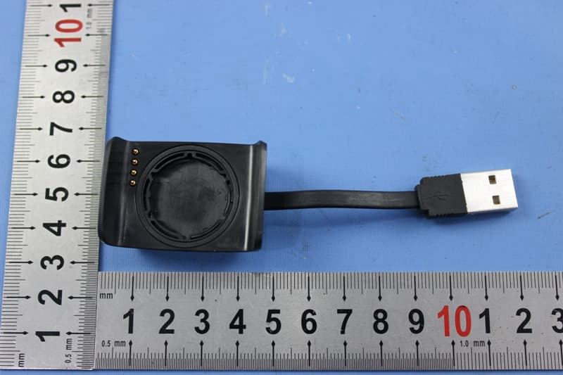
BOUDL8775
May 21, 2015BLE Activity Monitor with OHR
Equipment Class
DTS - Digital Transmission System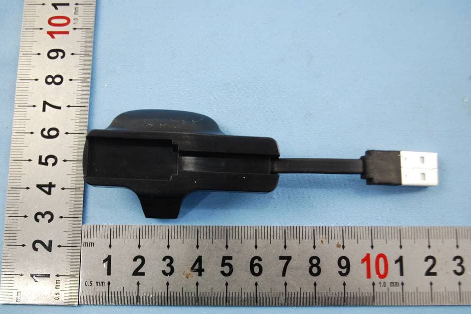
BOUDL8770
Sep 17, 2014Activity Monitor with OHR
Equipment Class
JBP - Part 15 Class B Computing Device Peripheral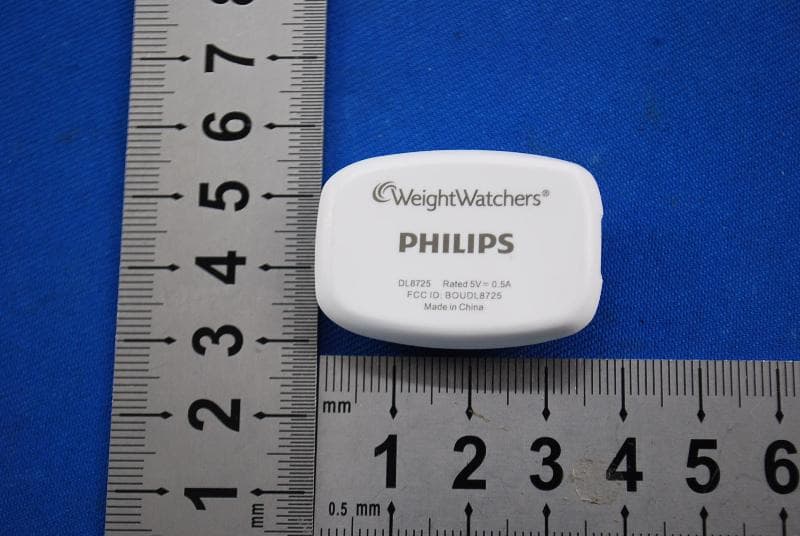
BOUDL8725
Jul 10, 2014Personal Activity Monitor with Bluetooth Function
Equipment Class
JBP - Part 15 Class B Computing Device Peripheral
BOUSCD501
May 28, 20141.9GHz DECT Baby Monitor - Baby Unit
Equipment Class
PUB - Part 15 Unlicensed PCS Base Station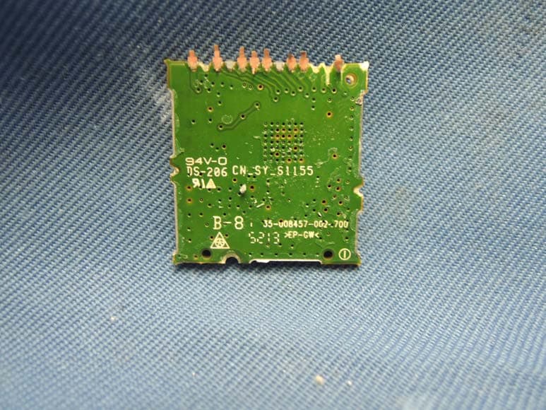
BOUSCD501H
May 28, 20141.9GHz DECT Baby Monitor - Parent Unit
Equipment Class
PUT - Part 15 Unlicensed PCS portable Tx worn on body