BOUTSU6000RF Remote Control
Philips Consumer Lifestyle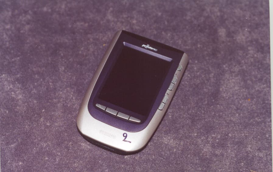
Click to zoom
Application Details
- Equipment Class
- DSC - Part 15 Security/Remote Control Transmitter
- Date of Grant
- May 02, 2001
- Application Purpose
- Original Equipment
- Date of Application
- May 02, 2001
- Equipment Note
- RF Remote Control
- Frequency Range
- 417.90000000 - 418.10000000
- Company
- Philips Consumer Lifestyle
- Country
- Hong Kong
Documents & Files
Document Text
Text extracted from the exhibit documents filed with the FCC. Open a document above to read the original.
Users Manual
User Guide 1 Taking a First Look2 Intelligent Remote Control2 Before You Start4 Getting Started6 Activating the Remote Control6 Defining the Brands of Your Devices7 Working with the Home Panel13 Operating a Device15 Adjusting the Settings18 Getting the Maximum out of it22 Introduction22 Redefining Brands24 Learning Commands25 Labeling Elements29 Adding and Moving31 Deleting and Restoring32 Recording Macros and Setting Timers35 Using the Remote Control with Radio Frequency39 ProntoPro Edit44 Troubleshooting46 General Problems46 Programming Problems47 Recharging Problems48 FAQ49 Maintaining the Remote Control51 Important notices51 Cleaning the Remote Control51 Overview of Symbols52 Specifications55 Index56 Table of Contents User Guide 2 Intelligent Remote Control The Intelligent Remote Control can be used for most devices that understand infrared (IR) remote control signals. Its easy-to-use touch screen with 256 colors and its intuitive interface makes it a perfect remote control for every user. The Remote Control (RC) is completely customizable. In the memory of the Remote Control, RC codes are stored to activate different brands for all kinds of video and audio devices. The Remote Control is set up by default to operate with Philips or Marantz devices. When you have other brands, you simply define the brands of your devices when you use the Remote Control for the first time. The Remote Control can also learn RC codes from existing remote controls. It is designed to add devices and functions, relabel buttons, record macros and set timers. With the ProntoPro Edit software you create your own control panels and define your personal look. If you want to operate devices from a distance or from an adjacent room, you can use the Remote Control with radio frequency (RF) signals and an RF Extender. The Appliance Direct-access buttons Sending eye 256 color LCD touch screen Learning eye Connection to the docking station Contrast dial Page Up button Serial port Taking a First Look Page Down button Action buttons Backlight button Reset button Battery compartment Battery cover Latch User Guide 3 Taking a First Look Remote Control icon: • Tap to enter the Mode menu and customize the Remote Control • Touch and hold to enter Setup mode Macro tab: To activate the Macro menu Device tab: To activate the Device menu Panel number: Shows active control panel The Touch Screen Control panel: To send commands to devices The Docking Station The docking station is used: • to charge the Remote Control; • to connect your Remote Control to your computer. The serial port on the docking station can be used as an alternative for the serial port on the Remote Control. Charging LEDAdapter connectorSerial port Connection for the Remote Control User Guide 4 Before You Start When you use the Remote Control for the first time, you will have to: • install the battery pack; • place the Remote Control in the docking station and charge the Remote Control. WarningUse the docking station only with the Philips NiMHrechargeable battery pack. We strongly advise you not to plug other appliances (like mobile phones, PDA’s, ...) into the docking station. This causes damage to the connector and the appliance. Installing the Battery Pack 1 Press the latch on the battery cover and remove the battery cover from the Remote Control. 2 Place the battery pack in the battery compartment. 3 Plug the cable of the battery pack in the connector as illustrated. Taking a First Look User Guide 5 4 Place the battery cover back on. NoteMake sure the cable of the battery pack does not get stuck between the mould and the battery cover. After a few seconds, the Remote Control starts up automatically and an Introduction screen appears. The Remote Control beeps twice to indicate that it has finished starting up. Because the battery pack of the Remote Control is not fully pre-charged, you will have to charge it as described below. Charging the Remote Control For charging the Remote Control you use the docking station. 1 Plug the power adapter into a wall outlet and connect it to the docking station. 2 Place the Remote Control in the docking station. Make sure you hold the Remote Control at an angle of 30° to 45° when you place the it in the docking station. Charging starts immediately. The green charging LED on the front of the docking station indicates charging takes place. When the Remote Control is fully charged, the LED goes off. NoteNormal charging time is 2 to 3 hours, depending on the condition of the battery pack. You can operate the Remote Control while it is being charged. The battery pack does not have to be entirely empty before recharging. You can place the Remote Control in the docking station at any time. When the battery pack is running low, the Low Battery icon flashes on the Remote Control icon . Recharge the Remote Control as soon as possible to ensure perfect performance. NoteThe Remote Control retains all settings when the battery pack has run out. You will only have to set the clock. See “Adjusting the Settings” on page 18. Taking a First Look 30° to 45° User Guide 6 Activating the Remote Control Turning on the Display and the Backlight The Remote Control’s display can be activated in three different ways: Tap the screen gently with your finger or a blunt, soft object like a pencil eraser. The display is activated. Tilt the Remote Control more than 50 degrees as illustrated. The display and the backlight of the direct-access buttons are activated. NoteIn the settings (p. 18) you can choose to deactivate the Pick Up sensor. Press the backlight button on the left side. The display and the backlight of the direct-access buttons are activated. When you turn on the display you see the Home panel. If another panel is displayed, tap the Home button . NoteIf the screen stays black or becomes blank, adjust the contrast using the contrast dial on the left side. The Remote Control has a switch-off feature: it automatically turns off to save power. In …
Text truncated - open the document above for the full version.
Cover Letter(s)
CONFIDENTIALITY REQUEST November 26, 2001 Federal Communications Commission Authorization and Evaluation Division 7435 Oakland Mills Road Columbia, MD 21046 Att: Richard Fabina Chief, Equipment Authorization Branch Re:FCC ID:BOUTSU6000 granted via Timco Engineering as a TCB grant on 5/03/01. Gentlemen: The subject FCC ID was issued a grant of certification by the referenced TCB, Timco Engineering, on May 3, 2001. There are items available on the FCC web site that Phillips Industrial Activities considers confidential that should not have been made available to the public, specifically the block diagram, operational description and schematics. This oversight or logistics error has resulted in an identical clone appearing in the marketplace which Phillips is certain could not have happened if the above information had not been accessible via the FCC web site. Notwithstanding any release of confidential information that has already occurred, Phillips is deeply concerned about the continued availability of this material on the FCC web site and wishes to have the above material marked confidential and withheld from routine examination by the public. What procedure must they follow in order to assure that the following material is marked confidential as expeditiously as possible? 1. Circuit diagrams submitted as Equipment Authorization electronic filing attachment: "Schematics". 2. Block diagram submitted as Equipment Authorization electronic filing attachment: "Block Diagram". 3. Technical description submitted as Equipment Authorization electronic filing attachment: "Operational Description". Specifically, these exhibits contain information relating to circuit function and complexity that could be of benefit to competitors. The material contains trade secrets and confidential information that Phillips Industrial Activities does not customarily release to the public and which is otherwise not generally available to the public. Please contact the undersigned by telephone at 410-531-3439, by fax at 410-531-0807, by email at [email protected], or by correspondence at the address below if there are any further questions or additional information needed concerning this filing. Rega rds, (signed) Phillip Inglis, TRP Inc. 14085 Howard Rd. Dayton, MD. 21036
ID Label/Location Info
NAME: J OB: PROGRAM: DAT E: F ONT S: P hilips IT C L Interleuv enla a n 74 • B -3001 L euv en T el. 32 16 390 884 CHANGE: 18/04/2001T O: REMARKS: REF. : 3104 200 0410. 2 L a bel T S 6000/01 Michiels F ra ns 20/09/2000 H elvetica C ondens ed fa mily/ Aria l cond.Adobe Illus tra tor 9. 0 R E MAR K : < outline artwork version T es ted to comply with F C C s ta nda rds for home a nd office us e TS6000/01 3104 207 11140 MADE IN B E L G IU M F AB R IQ U E E N B E L G IQ U E 6 V _____ _ _ _ 100 mA FCC ID : BOUTSU6000
ID Label/Location Info
FCC ID:BOUTSU6000 BOTTOM OF EUT
Operational Description
RF Explanation Specification RF transmitting module this page is intentionally left blank ISO 9000 certified © N.V. Philips Industrial Activities 2003 RF transmitting module RF Explanation Specification DocID: SD-0000-JWO23 Date: 2002-05-14 Version: 2.0 Status: Approved Author: JWO Remote Control Systems RF Explanation Specification RF transmitting module SD-0000-JWO23 2/11 2.0, Approved This document is published by: N.V. Philips Industrial Activities LoB Remote Control Systems Leuven, Belgium Please communicate any comments to: N.V. Philips Industrial Activities Remote Control Systems Interleuvenlaan 74 - 76 B-3001 LEUVEN Belgium Tel.: +32-16-390 911 Fax: +32-16-394 942 Remote Control Systems RF Explanation Specification RF transmitting module SD-0000-JWO23 3/11 2.0, Approved Table of contents 1. Introduction 4 1.1 Purpose of this document 4 1.2 Edition history 4 1.3 Definitions, acronyms and abbreviations 4 1.4 Reference documents 5 2. General product description 6 2.1 Product perspective 6 2.2 Product functions 6 2.3 User characteristics 6 2.4 General technical constraints 6 2.5 Assumptions and dependencies 6 3. Functional requirements 8 3.1 Description of processes 8 4. Non-functional requirements 10 5. Design constraints 11 5.1 Hardware compliance 11 Remote Control Systems RF Explanation Specification RF transmitting module SD-0000-JWO23 4/11 2.0, Approved 1. Introduction 1.1 Purpose of this document The purpose of this document is to define and identity the requirements for the RF transmitter module. All people with sufficient knowledge of the application domain should understand this document. 1.2 Edition history Version Status Date Author Modification(s) 0.1 Draft 2000-11-06 PGP Initial revision 0.2 Draft 2000-11-22 PGP Changes after review 1.0 Approved 2000-11-29 PGP Changes after review 2.0 Approved 2002-05-14 JWO Update for IR/RF RCMM code sequence, adapted for 36 kHz carrier only 1.3 Definitions, acronyms and abbreviations RCS Remote Control Systems IR Infra Red RF Radio Frequency OTP One Time Programmable ROM Read Only Memory RS232 Serial communication protocol RAM Random Access Memory uP Micro processor MSG Code Remote Control Systems RF Explanation Specification RF transmitting module SD-0000-JWO23 5/11 2.0, Approved 1.4 Reference documents [FEAS_FLASH] Title Feasibility Flash codes for Blaster Document ID SD-xxxx Author Peter Griep Publisher RCS Version 0.1 Date 2000-10-23 [RF_IR_EXT] Title Software Requirement Specification RF/IR Extender Document ID SD-7519-JWO02 Author Wouters, Johan Publisher RCS Version 0.2 Date 1999-07-13 Remote Control Systems RF Explanation Specification RF transmitting module SD-0000-JWO23 6/11 2.0, Approved 2. General product description 2.1 Product perspective The product, hereafter referred to as RF transmitter, comprises of a HW module including SW. The RF transmitter transmits RF control signals. The module can be built in as such or be integrated on a PWB of a control device (e.g. remote control). It will be used in conjunction with a receiving device that does a conversion of the transmitted RF control signal into IR control signals for controlling legacy IR reception devices (e.g. VCR, TV, STB, PreAmp,... ). 2.2 Product functions The function of the RF transmitter is to provide user control over devices that are not in line of sight, as is needed by legacy IR devices (VCR, TV, ...). Dedicated RF codes are transmitted and converted to any of the legacy IR protocols that are known by the RF receiving device. The receiver converts it back into the original IR codes and transmits those to the legacy IR reception devices. The RF transmitter is designed to carry IR codes over RF to RF receiving devices. The HW- SW combination used in the RF transmitter does not support any other type of transmission such as data transfer. 2.3 User characteristics The product will be used in the house. Users of the RF transmitter can be adults or kids. They have no particular technical expertise. 2.4 General technical constraints The product uses a fixed RF frequency that is in the license-free ISM band. No physical RF channels are provided so interference may occur with neighbouring devices that are transmitting at the same RF frequency. To limit susceptibility to neighbouring devices the RF codes must have a device ID and home ID where the product will check on at reception. The chosen ISM band frequency is subject to the RF emission standards, which may be different for different countries. Therefore the product hardware is configured specifically for use in a particularly country. Due to the limitations of the hardware, some specific IR codes cannot be transmitted correctly by the product. The specific IR codes are flash codes with a pulse totaltime of less than 286 μs, see also [FEAS_FLASH]. 2.5 Assumptions and dependencies Remote Control Systems RF Explanation Specification RF transmitting module SD-0000-JWO23 7/11 2.0, Approved Assumed is that the RF transmitter is able to handle all IR codes from the RCS universal codeset lookup table, with exception of some IR codes, see paragraph: general constraints. Next to that the RF transmitter should be able to handle any IR code that is learned by the user and stored on the transmitting device. Remote Control Systems RF Explanation Specification RF transmitting module SD-0000-JWO23 8/11 2.0, Approved 3. Functional requirements 3.1 Description of processes The RF transmitter generates two different RF codes parts to specify 1 legacy IR code to be generated by an RF/IR extender. The first RF codes part consists of a set of recognition codes that uses the RCMM IR-RF format (specified below) modulated at 36kHz to describe the carrier period of the legacy IR code. The second RF codes part consists of IR control codes (modulated over RF). These codes are hereafter referred to as the control envelope. The control envelope comprises of the envelope of legacy IR control code modulated at 36kHz. 3.1.1 Recognition code fo…
Text truncated - open the document above for the full version.
Test Report
REPORT# 11011-2 DATE OF TEST: 4-12-01 PHILIPS CONSUMER ELECTRONICS COMPANY EMI LAB P.O. 14810 KNOXVILLE, TN 37914-1810 RADIATED RF LEVEL MANUFACTURER: Philips MODEL: Pronto Remote Control SUPPORT EQUIPMENT: Unit in Charger FREQUENCYDbuV/MDbuV/MDbuV/MDbuV/M (Mhz)HORIZ.VERT.LIMITDELTA 418.072.7 72.180.3-7.3 836.052.748.761.9-9.2 1254.043.4 44.361.9-17.6 1672.046.649.953.9-4.0 2090.058.256.561.9 -3.7 2508.0 NO EMISSIONSFOUND 2926.0NO EMISSIONSFOUND 3344.0NO EMISSIONSFOUND 3762.0NO EMISSIONSFOUND 4182.0 NO EMISSIONSFOUND 4598.0 NO EMISSIONSFOUND FOR MEASUREMENTS BELOW 1000 MHZ, THE READINGS ARE REPORTED IN QUASI-PEAK. ALL OTHER READINGS ARE REPORTED AS AVERAGE READINGS. DELTA REFERS TO THE DB DIFFERENCE BETWEEN THE HIGHER OF THE HORIZONTAL AND THE VERTICAL READINGS AND THE DB LIMIT AT THAT FREQUENCY. TEST DISTANCE BETWEEN DEVICE UNDER TEST AND RECEIVING ANTENNA WAS 3 METERS. REPORT# 11011-2 DATE OF TEST: 4-12-01 PHILIPS CONSUMER ELECTRONICS COMPANY EMI LAB P.O. 14810 KNOXVILLE, TN 37914-1810 RADIATED RF LEVEL MANUFACTURER: Philips MODEL: Pronto Remote Control SUPPORT EQUIPMENT: Unit on Side FREQUENCYDbuV/MDbuV/MDbuV/MDbuV/M (Mhz) HORIZ.VERT.LIMITDELTA 418.077.0 70.480.3-3.3 836.053.253.061.9-8.7 1254.046.0 42.761.9-15.9 1672.052.051.153.9-1.9 2090.059.056.261.9 -2.9 2508.0 NO EMISSIONSFOUND 2926.0NO EMISSIONSFOUND 3344.0NO EMISSIONSFOUND 3762.0NO EMISSIONSFOUND 4182.0 NO EMISSIONSFOUND 4598.0 NO EMISSIONSFOUND FOR MEASUREMENTS BELOW 1000 MHZ, THE READINGS ARE REPORTED IN QUASI-PEAK. ALL OTHER READINGS ARE REPORTED AS AVERAGE READINGS. DELTA REFERS TO THE DB DIFFERENCE BETWEEN THE HIGHER OF THE HORIZONTAL AND THE VERTICAL READINGS AND THE DB LIMIT AT THAT FREQUENCY. TEST DISTANCE BETWEEN DEVICE UNDER TEST AND RECEIVING ANTENNA WAS 3 METERS. REPORT# 11011-2 DATE OF TEST: 4-12-01 PHILIPS CONSUMER ELECTRONICS COMPANY EMI LAB P.O. 14810 KNOXVILLE, TN 37914-1810 RADIATED RF LEVEL MANUFACTURER: Philips MODEL: Pronto Remote Control SUPPORT EQUIPMENT: Unit on End FREQUENCYDbuV/MDbuV/MDbuV/MDbuV/M (Mhz) HORIZ.VERT.LIMITDELTA 418.072.5 76.380.3-4.0 836.051.249.861.9-10.7 1254.041.8 41.061.9-20.0 1672.051.349.953.9-2.6 2090.057.354.961.9 -4.6 2508.0 NO EMISSIONSFOUND 2926.0NO EMISSIONSFOUND 3344.0NO EMISSIONSFOUND 3762.0NO EMISSIONSFOUND 4182.0 NO EMISSIONSFOUND 4598.0 NO EMISSIONSFOUND FOR MEASUREMENTS BELOW 1000 MHZ, THE READINGS ARE REPORTED IN QUASI-PEAK. ALL OTHER READINGS ARE REPORTED AS AVERAGE READINGS. DELTA REFERS TO THE DB DIFFERENCE BETWEEN THE HIGHER OF THE HORIZONTAL AND THE VERTICAL READINGS AND THE DB LIMIT AT THAT FREQUENCY. TEST DISTANCE BETWEEN DEVICE UNDER TEST AND RECEIVING ANTENNA WAS 3 METERS. REPORT# 11011-2 DATE OF TEST: 4-12-01 PHILIPS CONSUMER ELECTRONICS COMPANY EMI LAB P.O. 14810 KNOXVILLE, TN 37914-1810 RADIATED RF LEVEL MANUFACTURER: Philips MODEL: Pronto Remote Control SUPPORT EQUIPMENT: Unit Flat FREQUENCYDbuV/MDbuV/MDbuV/MDbuV/M (Mhz) HORIZ.VERT.LIMITDELTA 418.073.9 67.980.3-6.4 836.053.345.361.9-8.6 1254.041.7 46.761.9-15.2 1672.048.750.053.9-12.0 2090.058.757.161.9 -3.2 2508.0 NO EMISSIONSFOUND 2926.0NO EMISSIONSFOUND 3344.0NO EMISSIONSFOUND 3762.0NO EMISSIONSFOUND 4182.0 NO EMISSIONSFOUND 4598.0 NO EMISSIONSFOUND FOR MEASUREMENTS BELOW 1000 MHZ, THE READINGS ARE REPORTED IN QUASI-PEAK. ALL OTHER READINGS ARE REPORTED AS AVERAGE READINGS. DELTA REFERS TO THE DB DIFFERENCE BETWEEN THE HIGHER OF THE HORIZONTAL AND THE VERTICAL READINGS AND THE DB LIMIT AT THAT FREQUENCY. TEST DISTANCE BETWEEN DEVICE UNDER TEST AND RECEIVING ANTENNA WAS 3 METERS.
Test Report
1Thu 12/Apr/2001 15:39:52 Ready MARKER AMPLITUDE IN dBuV 31dBuV Specefication FCC Class B ATTEN 10 MARKER FREQ. 9970k MARKER AMPLITUDE 36uV RES BW 10k VID BW 10k SWEEP TIME 50 Comments REPORT #11011-2 PEAK READING Ref Level 0.5m Date Display Thu 12/Apr/2001 15:30:58 Model Number PRONTO REMOTE CONTROL Manufacture PHILIPS Limit tested to Q.P. Phase X FCC Class B 450k30M1000k10M 0.25m 0 50u 0.1m 0.15m 0.2m Frequency Magnitude Trace A Trace B Peak Limit Line Auto Scale 3697k1.5ux:y: Main
Test Report
Functional description TSU6000 1) General description of device The TSU6000 is a color LCD touch screen universal remote control. It is intended to operated a large variety of TV’s, VCR’s, hi-fi combinations,... To minimize the number of hard buttons, an LCD is used to display the buttons and a touch screen will sense whether a button is pressed. It also offers an intuitive user interface. In order to accommodate a wide range of brands, a database is include to pick the right code set for a particular device. To be future proof, the user has the possibility to update the database and/or software in the device by connecting the TSU6000 via a cable to the serial com port of a PC. With the included software (Pronto Edit), the user can customize his device. Next to having a database, the device is also capable of learning IR (infrared) codes via an infrared receiver. The received code is stored aboard the flash memory. While the larger part of the controlled devices by the TSU6000 are controlled by infrared, the TSU6000 is also capable of sending out codes via RF. This operates in combination with a remote control extender, which is sold separately. The power source for this device is a rechargable battery pack (4 x AAA NiMH pack with temperature sensor and poly fuse). The TSU6000 is combined with the DS6000, which is the battery charger for this device. 2) Main use This device is a standalone remote control device, for indoor use only. When upgrading the software or user interface, it has to be linked via the included cable to the com port of a PC. When the battery is empty, it must be recharged with the included docking device. 3) Circuit description The function of the device is build around the Motorola Dragonball uP (IC 7001). Via its build in memory controller, it uses 512KB SRAM (IC 7006) and 8 MB of flash memory (IC 7059). The Flash is used as storage for the database, programs and learned IR codes. The SRAM is used to run the programs from and to hold copies of the flash blocks. An additional footprint to add memory is provided, but not used in this device (IC7005). IC 7067 is the glue logic between uP and memory. In stead of using the on board LCD controller, there is chosen to use an external LCD controller: this is IC 7060. It is attached on the memory and data bus of the uP. An image is build in a particular address space of the uP and translated by the LCD controller in order to display a bitmap on the color LCD. The color LCD is attached to the pwb via connector 1002. The clock needed to operate the LCD controller comes from the uP and is 8MHz. The clock frequency to operate the uP is derived from a low frequency crystal: 32.768 kHz. Via the internal PLL from the uP, this is multiplied to 16.6 MHz. This clock does NOT leaves the uP. The hardware round components 7066 and 3125 are to power down the LCD when the device is in the sleep mode and also regulate the contrast of the LCD. IC 7004 is a touch screen controller: it has 4 connections to the LCD via connector 1002. It provides x and y coordinates to the uP via the SPI port of the uP. Via the auxiliary input of ic 7004, the battery voltage is measured to estimate the remained capacity of the battery. ESD protection of the touch screen is provides via diodes 6001...6004. The generation of IR signals is proved by combining the PWM output of the uP with some glue logic (ic’s 7011, 7012, 7007, 7009): for an example of what the wave form looks likes: see next page. The carrier frequency is generated by the PWM of the uP. This is a square wave with a frequency between 36kHz and 455 kHz, dependent on the format of the IR code. Different brands use different carrier frequencies. Because the generated square wave can also be an audible signal, which goes to the piezo driver, a demultiplexer is used (IC 7007-A and –C). The output of the PWM goes via the multiplexer (IC 7009) to IRQ7 and TIN1. Each carrier pulse is counted and when the amount of carrier pulses equals the value of the compare register of the counter (which is in the uP), IC 7012 ( is commanded via TOUT of the uP) will stop the carrier from being transferred past IC 7007-B. Now the compare value in the counter register is set to the amount of pulses that are not allowed to be send out. Those pulses are count and when this value is reached, IC 7012 will command IC 7007B to let the pulses true again. In this way, any pulse train can be obtained which forms a command. The IC’s 7012 and 7071 forms a switch that direct the pulse train to the IR driver (transistors 7064 and 7013), or to the RF transmitter. There are two infrared receivers: 6010 and 6028. The 6010 is used to learn IR codes that are send out by other remotes on a short distance (typical 1 – 10 cm), while the 6028 is intended in two way infrared communication up to 10 meter. In order to attach the device to a communication port of a PC, it is necessary to convert the signal of the UART (in uP) that has a level between 0 and +3.3V, to an RS232 compatible level. The RS232 spec requires for a logic “1” a level between –15 and –3.3V, for a logic “0” a level between +3.3 and +15V. The transistors 7016, 7017 and 7018 will provide an output level between Vbat ( minimum + 4.2 V) and the voltage supplied by the TX of the PC. Additional components are used to guaranty ESD protection and to detect if the device is hooked up to a PC. A key matrix provides the device with some frequently used buttons such as volume up & down, channel up & down, page up & down,.. Some of the buttons are backlighted by LED’s (6042 to 6046). Example of IR protocol: The circuit around 7035 is the reset circuit for the uP. The tilt switches 1020 and 1026 will wake up the device if tilted under an angle of 40 º. The power management block has 3 main blocks: the voltage monitor IC 7028, The 3.3V LDO and the enable switch (7047 or 7024, 7029 and 7030). When the battery voltage is lower than 4.2V, IC 7028 will shut down the LDO (IC 7023) by opening th…
Text truncated - open the document above for the full version.
Contact Information
Applicant
Tee Wee Jaw(Director, Project Management)
Test Firm
Global Testing Laboratory, LLCCaile Gonzalez
Technical Specifications
| # | Rule Parts | Frequency Range | Power Output |
|---|---|---|---|
| 1 | 15.231 | 417.9 MHz - 418.1 MHz | - |
Other Applications from Philips Consumer Lifestyle
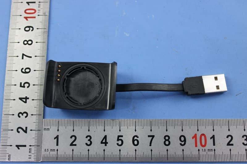
BOUDL8775
May 21, 2015BLE Activity Monitor with OHR
Equipment Class
DTS - Digital Transmission System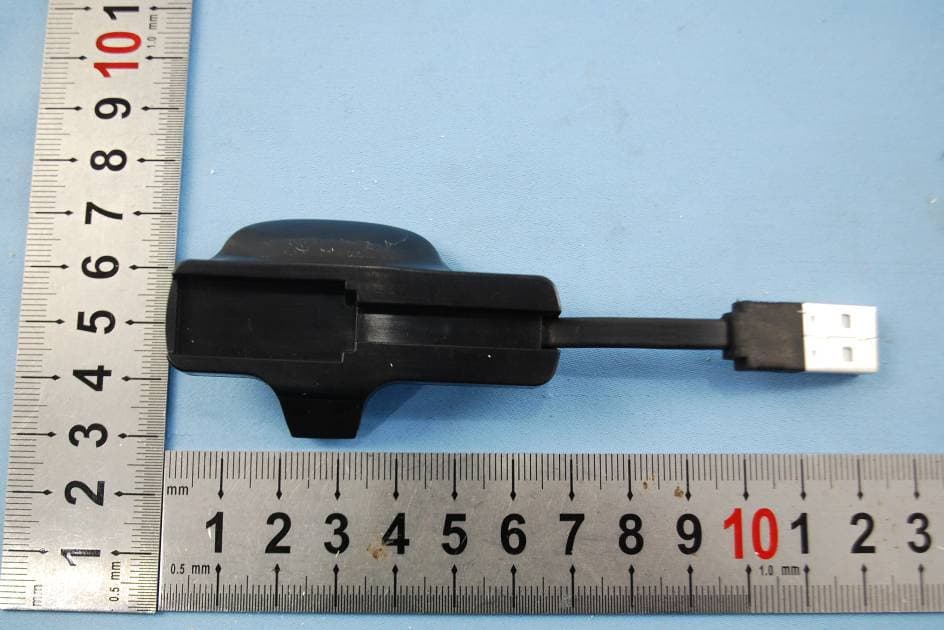
BOUDL8770
Sep 17, 2014Activity Monitor with OHR
Equipment Class
JBP - Part 15 Class B Computing Device Peripheral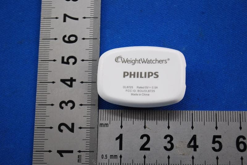
BOUDL8725
Jul 10, 2014Personal Activity Monitor with Bluetooth Function
Equipment Class
JBP - Part 15 Class B Computing Device Peripheral
BOUSCD501
May 28, 20141.9GHz DECT Baby Monitor - Baby Unit
Equipment Class
PUB - Part 15 Unlicensed PCS Base Station
BOUSCD501H
May 28, 20141.9GHz DECT Baby Monitor - Parent Unit
Equipment Class
PUT - Part 15 Unlicensed PCS portable Tx worn on body