BQI00DT-7000DT-7000 Instrument Transceiver
Data Critical Corporation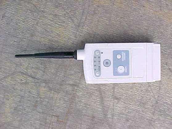
Click to zoom
Application Details
- Equipment Class
- DXX - Part 15 Low Power Communication Device Transmitter
- Date of Grant
- Aug 13, 2002
- Application Purpose
- Original Equipment
- Date of Application
- Dec 11, 2000
- Equipment Note
- DT-7000 Instrument Transceiver
- Frequency Range
- 608.70000000 - 612.96000000
- Company
- Data Critical Corporation
- Country
- United States
Documents & Files
Document Text
Text extracted from the exhibit documents filed with the FCC. Open a document above to read the original.
Users Manual
DT-7000 Operator’s Manual, Revision A i DT-7000 OPERATOR’S MANUAL Software Version 1.01 15222 Del Amo Ave. Tustin, California 92780 714.546.0147 Fax 714.571.3945 Toll-free Telephone 800.888.0077 www.vitalcom.com ii DT-7000 Operator’s Manual, Revision A Copyright ©2000 VitalCom Inc. All rights reserved. 15222 Del Amo Avenue, Tustin, California 92780 Limited Software License and Equipment Use All software licensed by VitalCom to Customers is licensed under a limited, non- transferable license and VitalCom reserves all rights not expressly granted. The soft- ware license permits the customer to use the software only on equipment purchased from VitalCom. The customer may not copy, modify, loan, rent, lease or otherwise transfer the software or assign, transfer or sub-license the software to any other party without VitalCom’s prior written consent, and any attempt to do so will render the software license null and void. The customer may not sublet the equipment sold to it by VitalCom and will not permit it to be used by anyone other than the customer’s qualified personnel. Modification or hooking up of other equipment to the VitalCom equipment, including software and related instruments cannot be made without Vital- Com’s written authorization. Manuals or other written documentation may not be copied or distributed without VitalCom’s authorization. Mobile-PatientViewer, OpenNet, PatientBrowser, SiteLink, and VitalCom PatientNet are trademarks of VitalCom Inc. DINAMAP is a registered trademark of Critikon Company LLC. Propaq and Encore are trademarks of Protocol Systems, Inc. Passport is a registered trademark of Datascope Corp. Microsoft and Windows are registered trademarks, and Windows NT is a trademark of Microsoft Corporation in the United States of America and other countries. While we have endeavored to supply as complete and accurate a list as possible, Vital- Com makes no warranties, express or implied, as to the completeness and accuracy of this list. This list does not constitute an endorsement of any particular manufacturer. DT-7000 Operator’s Manual, Revision A iii All information contained herein is subject to the rights and restrictions on the title page. TABLE OF CONTENTS Introduction ........................................................................................................................................ 5 System Overview ...................................................................................................................... 5 Equipment Site Selection/Location........................................................................................... 5 Clinical Use and Responsibility ................................................................................................ 6 User Warnings, Cautions, and Notes ........................................................................................ 7 Definitions of International Symbols ........................................................................................ 9 Use and Maintenance ...................................................................................................................... 12 Specifications .................................................................................................................................. 19 Statement of Compliance................................................................................................................ 20 iv DT-7000 Operator’s Manual, Revision A All information contained herein is subject to the rights and restrictions on the title page. This page is intentionally left blank. INTRODUCTION DT-7000 Operator’s Manual, Revision A 5 All information contained herein is subject to the rights and restrictions on the title page. INTRODUCTION System Overview Wireless Medical Telemetry Services (WMTS) Remote Transceivers provide the link between the patient and the Central Station through the newly approved 608 - 614 MHz Medical Telemetry frequency band. The ambulatory and bedside device trans- ceivers communicate data to the Central Station through the Access Point transceiver. In addition, the transceivers are capable of receiving control commands for self-use or connection transfer. The PatientNet ambulatory transceiver is the DT-4500. This transceiver is worn by the patient and usually carried in a gown pocket or paper pouch, and used with a 6-wire leadset connected to the electrodes on the patient. The DT-7000 and 7001 are the PatientNet bedside-device transceivers and are physi- cally connected to bedside monitors (other manufacturers’ bedside monitors and ven- tilators). The DR-10000 Access Point transceiver collects data from the ambulatory and bed- side transceivers, sends that data to the Central Station, and transmits control data to the transceiver devices. Equipment Site Selection/Location The DT-7000 transceiver is attached to a bedside device through the use of the adhe- sive strip or screws. INTRODUCTION 6 DT-7000 Operator’s Manual, Revision A All information contained herein is subject to the rights and restrictions on the title page. Clinical Use and Responsibility CAUTION: United States Federal law restricts this device to sale by, or on the order of, a physician or properly licensed practitioner. The PatientNet System provides the technology to monitor cardiac rhythms, vital signs, and equipment alarms for patients with various levels of acuity in multiple patient care settings. The monitoring system does not replace physicians, caregivers or system operators. We recognize that machines are not capable of replacing human judgment, and emphasizes the importance of the human element in the determination of any patient care interventions. Implementation of clearly documented and communicated patient care guidelines and protocols accepted by the healthcare team is essential to the optimal use of the PatientNet System. The following list is intended to provide guidance in determining potential high r…
Text truncated - open the document above for the full version.
Attestation Statements
1 Worst Case Transmit Duty Cycle for WIT608 The duty cycle derating factor used in the calculation of average radiated limits (per 15.209 for frequencies above 1GHz) is described below. This factor was calculated by first determining the worst case scenario for system operation - worst case being defined as the scenario when the WIT608 would be transmitting the longest period during a dwell. This worst case operating scenario is as follows: 1) data flow is almost completely unidirectional (that is, one radio is relaying a large amount of data to the other radio with only synchronization data being passed back the other direction) 2) The amount of data being fed to the sending radio is exactly portioned out to fit the maximum packet size allowable (252 bytes). The radio cannot send more than 252 bytes on a single channel – additional data must be sent on the next hop. For this example, a remote unit is transferring monitoring data to a base unit. Maximum transmit time by Remote on a single channel: = 252 bytes * 8 bits/byte * (1/230.4Kbps) = 8.75ms Hop duration (dwell time) for this scenario is 35.28ms. Given that we have 32 channels in our hop set, it takes 1.12896 seconds to go through the entire hop table and repeat a transmission on the same channel. Therefore, only 8.75 milliseconds worth of data can be transmitted on a single channel in any 100 milliseconds time period. The transmission duty cycle correction factor is then calculated as: 20 * Log 10 (8.75ms/100ms) = -21.2 dB A 35% duty cycle was assumed during the testing, which is the hop duration.
ID Label/Location Info
Label, Rear, DT-700X DSKimball 20000922 VITALCOM INCORPORATED PROPRIETARY RIGHTS ARE INCLU- DED IN THE INFORMATION DISCLOSED HEREIN. NEITHER THIS DOC- UMENT NOR THE INFORMATION DISCLOSED HEREIN SHALL BE RE- PRODUCED OR TRANSFERRED TO OTHER DOCUMENTS OR USED OR DISCLOSED TO OTHERS FOR MANUFACTURING OR FOR ANY OTHER PURPOSE EXCEPT AS SPECIFICALLY AUTHORIZED IN WRITING BY VITALCOM INCORPORATED. NOTES: UNLESS OTHERWISE SPECIFIED 1 of 1 SolidWorks 1:1 ARTWORK REV CHECKED BY ENGINEERING DRAWN DOCUMENT CONTROL RELEASE .XXX ± .010 .XX ± .03 DECIMALS DO NOT SCALE DRAWING DIMENSIONS ARE IN INCHES UNLESS OTHERWISE SPECIFIED FRACTIONS ± 1/8 MATERIAL FINISH TOLERANCES ARE: ANGLES ± 5° APPROVALS SIGNATURESDATE B PGM SIZE 12111102 SHEET (714) 546-0147 15222 Del Amo Avenue, Tustin, CA 92780 DWG. NO. FILE SCALE REV B DESCRIPTION REVISION HISTORY REVDCR # REVISED BY/DATE FOR INFORMATION ONLY NEXT ASSYUSED ON APPLICATION I T A LVCO M <material> <finish> FAX (714) 546-0084 1. Interpret dimensions and tolerances per ASME Y14.5M-1994. 2. Material: Polyester, Autotex 2V8 0.008 thick. 3. Adhesive: 3M 468 MP 4. Artwork per table. Use VitalCom artwork for colors, graphics, and fonts. 5. Background color: Match Bayer Makroblend EL700, color #3735 6. This drawing to be used in conjunction with supplied 3D data file. -002 DT-7001 12111102-202.ai -001 DT-7000 12111102-201.ai - # Version Artwork B Add dimensions and notes 1 and 6 00-402A B 1.855 2.055 1.445 3.968 R .120 2.940 R 5.115 1.070 R .260 R .600 .010
ID Label/Location Info
-201 SHOWN THIS FILE FOR INTERNAL USE ONLY. THE FONTS IN THIS FILE HAVE NOT BEEN CHANGED TO OUTLINES DO NOT SHOW BORDER A Component of the PATENT PENDING PatientNet Suite of Products TM DT-7000 THIS DEVICE COMPLIES WITH FCC RULES PART 15. OPERATION IS SUBJECT TO THE FOLLOWING CONDITIONS: (1) THIS DEVICE MAY NOT CAUSE HARMFUL INTERFERENCE AND (2) THIS DEVICE MUST ACCEPT ANY INTERFERENCE THAT MAY BE RECEIVED, INCLUDING INTERFERENCE THAT MAY CAUSE UNDESIRED OPERATION. BQIOODT-7000 FCC ID: Federal law restricts this device to sale by or on the order of a Physician or other licensed Practitioner CAUTION: FREQUENCY: 608MHz - 614MHz Instrument Transceiver UL 2601-1/CAN/CSA C22.2 NO.601.1 79VK Instrument Transceiver MANUFACTURED IN USA BY VITALCOM TUSTIN, CA 92780 12111102-001 Rev.C IPX1 12111102 CC 12111102_C_3.AI AI 3 OF 5 VITALCOM
Test Report
FCC ID: BQI00DT-7000 Report No.: B01211D1 114 OLINDA DRIVE, BREA, CALIFORNIA 92823 PHONE: (714) 579-0500 FAX: (714) 579-1850 Page 1 of 16 FCC PART 15, SUBPART B AND C TEST REPORT for TRANSCEIVER Model: DT-7000 Prepared for VITALCOM 15222 DEL AMO AVENUE TUSTIN, CALIFORNIA 92780 COMPATIBLE ELECTRONICS INC. 114 OLINDA DRIVE BREA, CALIFORNIA 92823 (714) 579-0500 DATE: DECEMBER 12, 2000 REPORT APPENDICES TOTAL BODY A B C D PAGES 16 2 2 15 23 58 This report shall not be reproduced except in full, without the written approval of Compatible Electronics. FCC ID: BQI00DT-7000 Report No.: B01211D1 114 OLINDA DRIVE, BREA, CALIFORNIA 92823 PHONE: (714) 579-0500 FAX: (714) 579-1850 Page 2 of 16 TABLE OF CONTENTS Section / Title PAGE GENERAL REPORT SUMMARY 4 SUMMARY OF TEST RESULTS 4 1. PURPOSE 5 2. ADMINISTRATIVE DATA 6 2.1 Location of Testing 6 2.2 Traceability Statement 6 2.3 Cognizant Personnel 6 2.4 Date Test Sample was Received 6 2.5 Disposition of the Test Sample 6 2.6 Abbreviations and Acronyms 6 3. APPLICABLE DOCUMENTS 7 4. Description of Test Configuration 8 4.1 Description of Test Configuration - EMI 8 4.1.1 Cable Construction and Termination 9 5. LISTS OF EUT, ACCESSORIES AND TEST EQUIPMENT 10 5.1 EUT and Accessory List 10 5.2 EMI Test Equipment 11 6. TEST SITE DESCRIPTION 12 6.1 Test Facility Description 12 6.2 EUT Mounting, Bonding and Grounding 12 7. Test Procedures 13 7.1 Conducted Emissions Test 13 7.2 Radiated Emissions (Spurious and Harmonics) Test 14 7.3 RF Band Edges 15 8. CONCLUSIONS 16 FCC ID: BQI00DT-7000 Report No.: B01211D1 114 OLINDA DRIVE, BREA, CALIFORNIA 92823 PHONE: (714) 579-0500 FAX: (714) 579-1850 Page 3 of 16 LIST OF APPENDICES APPENDIX TITLE A Modifications to the EUT B Additional Models Covered Under This Report C Diagrams, Charts and Photos • Test Setup Diagrams • Radiated Emissions Photos • Antenna and Effective Gain Factors D Data Sheets LIST OF FIGURES FIGURE TITLE 1 Conducted Emissions Test Setup 2 Plot Map And Layout of Test Site FCC ID: BQI00DT-7000 Report No.: B01211D1 114 OLINDA DRIVE, BREA, CALIFORNIA 92823 PHONE: (714) 579-0500 FAX: (714) 579-1850 Page 4 of 16 GENERAL REPORT SUMMARY This electromagnetic emission test report is generated by Compatible Electronics Inc., which is an independent testing and consulting firm. The test report is based on testing performed by Compatible Electronics personnel according to the measurement procedures described in the test specifications given below and in the "Test Procedures" section of this report. The measurement data and conclusions appearing herein relate only to the sample tested and this report may not be reproduced in any form unless done so in full with the written permission of Compatible Electronics. This report must not be used to claim product endorsement by NVLAP or any other agency of the U.S. Government. Device Tested: Transceiver Model: DT-7000 S/N: N/A Product Description: See Expository Statement. Modifications: The EUT was not modified during the testing. Manufacturer: Vitalcom 15222 Del Amo Avenue Tustin, California 92780 Test Date: December 11, 2000 Test Specifications : EMI requirements Limits: EN 55022: 1998 Class B and CFR Title 47, Part 15 Subpart C, Sections 15.205, 15.209, and 15.242 Test Procedure: ANSI C63.4: 1992 Test Deviations: The test procedure was not deviated from during the testing. SUMMARY OF TEST RESULTS TEST DESCRIPTION RESULTS 1 Conducted RF Emissions, 450 kHz - 30 MHz Complies with the Class B limits of EN 55022: 1998 2 Radiated RF Emissions, 10 kHz – 6140 MHz Complies with the Class B limits of EN 55022: 1998; CFR Title 47, Part 15, Subpart C, sections 15.205, 15.209 and 15.242 FCC ID: BQI00DT-7000 Report No.: B01211D1 114 OLINDA DRIVE, BREA, CALIFORNIA 92823 PHONE: (714) 579-0500 FAX: (714) 579-1850 Page 5 of 16 1. PURPOSE This document is a qualification test report based on the Electromagnetic Interference (EMI) tests performed on the Transceiver Model: DT-7000. The EMI measurements were performed according to the measurement procedure described in ANSI C63.4: 1992. The tests were performed in order to determine whether the electromagnetic emissions from the equipment under test, referred to as EUT hereafter, are within the Class B specification limits defined by C.I.S.P.R. Publication 22 for Information Technology Equipment; and CFR Title 47, Part 15, Subpart C, sections 15.205, 15.209, and 15.242. Under paragraph E of section 15.107 and paragraph G of section 15.109 of the Code of Federal Regulations Title 47, Part 15 of the FCC rules, FCC accepts the international standards set forth in C.I.S.P.R. Publication 22. FCC ID: BQI00DT-7000 Report No.: B01211D1 114 OLINDA DRIVE, BREA, CALIFORNIA 92823 PHONE: (714) 579-0500 FAX: (714) 579-1850 Page 6 of 16 2. ADMINISTRATIVE DATA 2.1 Location of Testing The EMI tests described herein were performed at the test facility of Compatible Electronics, 114 Olinda Drive, Brea, California 92823. 2.2 Traceability Statement The calibration certificates of all test equipment used during the test are on file at the location of the test. The calibration is traceable to the National Institute of Standards and Technology (NIST) . 2.3 Cognizant Personnel Vitalcom Gus Testa RF Engineer Compatible Electronics Inc. Kyle Fujimoto Test Engineer Scott McCutchan Lab Manager 2.4 Date Test Sample was Received The test sample was received on December 11, 2000. 2.5 Disposition of the Test Sample The test sample was returned to Vitalcom on December 12, 2000. 2.6 Abbreviations and Acronyms The following abbreviations and acronyms may be used in this document. RF Radio Frequency EMI Electromagnetic Interference EUT Equipment Under Test P/N Part Number S/N Serial Number HP Hewlett Packard ITE Information Technology Equipment CML Corrected Meter Limit LISN Line Impedance Stabilization Network CFR Code of Federal Regulations FCC ID: BQI00DT-7000 Report No.: B01211D1 114 OLINDA DRIVE, BREA, CALIFORNIA 92823 PHONE: (714) 579-0500 FAX: (714) 579-1850 Page 7 of 1…
Text truncated - open the document above for the full version.
Test Report
FCC ID: BQI00DT-7000 Report No.: B01211D1 114 OLINDA DRIVE, BREA, CALIFORNIA 92823 PHONE: (714) 579-0500 FAX: (714) 579-1850 Page 1 of 16 FCC PART 15, SUBPART B AND C TEST REPORT for TRANSCEIVER Model: DT-7000 Prepared for VITALCOM 15222 DEL AMO AVENUE TUSTIN, CALIFORNIA 92780 COMPATIBLE ELECTRONICS INC. 114 OLINDA DRIVE BREA, CALIFORNIA 92823 (714) 579-0500 DATE: DECEMBER 12, 2000 REPORT APPENDICES TOTAL BODY A B C D PAGES 16 2 2 15 23 58 This report shall not be reproduced except in full, without the written approval of Compatible Electronics. FCC ID: BQI00DT-7000 Report No.: B01211D1 114 OLINDA DRIVE, BREA, CALIFORNIA 92823 PHONE: (714) 579-0500 FAX: (714) 579-1850 Page 2 of 16 TABLE OF CONTENTS Section / Title PAGE GENERAL REPORT SUMMARY 4 SUMMARY OF TEST RESULTS 4 1. PURPOSE 5 2. ADMINISTRATIVE DATA 6 2.1 Location of Testing 6 2.2 Traceability Statement 6 2.3 Cognizant Personnel 6 2.4 Date Test Sample was Received 6 2.5 Disposition of the Test Sample 6 2.6 Abbreviations and Acronyms 6 3. APPLICABLE DOCUMENTS 7 4. Description of Test Configuration 8 4.1 Description of Test Configuration - EMI 8 4.1.1 Cable Construction and Termination 9 5. LISTS OF EUT, ACCESSORIES AND TEST EQUIPMENT 10 5.1 EUT and Accessory List 10 5.2 EMI Test Equipment 11 6. TEST SITE DESCRIPTION 12 6.1 Test Facility Description 12 6.2 EUT Mounting, Bonding and Grounding 12 7. Test Procedures 13 7.1 Conducted Emissions Test 13 7.2 Radiated Emissions (Spurious and Harmonics) Test 14 7.3 RF Band Edges 15 8. CONCLUSIONS 16 FCC ID: BQI00DT-7000 Report No.: B01211D1 114 OLINDA DRIVE, BREA, CALIFORNIA 92823 PHONE: (714) 579-0500 FAX: (714) 579-1850 Page 3 of 16 LIST OF APPENDICES APPENDIX TITLE A Modifications to the EUT B Additional Models Covered Under This Report C Diagrams, Charts and Photos • Test Setup Diagrams • Radiated Emissions Photos • Antenna and Effective Gain Factors D Data Sheets LIST OF FIGURES FIGURE TITLE 1 Conducted Emissions Test Setup 2 Plot Map And Layout of Test Site FCC ID: BQI00DT-7000 Report No.: B01211D1 114 OLINDA DRIVE, BREA, CALIFORNIA 92823 PHONE: (714) 579-0500 FAX: (714) 579-1850 Page 4 of 16 GENERAL REPORT SUMMARY This electromagnetic emission test report is generated by Compatible Electronics Inc., which is an independent testing and consulting firm. The test report is based on testing performed by Compatible Electronics personnel according to the measurement procedures described in the test specifications given below and in the "Test Procedures" section of this report. The measurement data and conclusions appearing herein relate only to the sample tested and this report may not be reproduced in any form unless done so in full with the written permission of Compatible Electronics. This report must not be used to claim product endorsement by NVLAP or any other agency of the U.S. Government. Device Tested: Transceiver Model: DT-7000 S/N: N/A Product Description: See Expository Statement. Modifications: The EUT was not modified during the testing. Manufacturer: Vitalcom 15222 Del Amo Avenue Tustin, California 92780 Test Date: December 11, 2000 Test Specifications : EMI requirements Limits: EN 55022: 1998 Class B and CFR Title 47, Part 15 Subpart C, Sections 15.205, 15.209, and 15.242 Test Procedure: ANSI C63.4: 1992 Test Deviations: The test procedure was not deviated from during the testing. SUMMARY OF TEST RESULTS TEST DESCRIPTION RESULTS 1 Conducted RF Emissions, 450 kHz - 30 MHz Complies with the Class B limits of EN 55022: 1998 2 Radiated RF Emissions, 10 kHz – 6140 MHz Complies with the Class B limits of EN 55022: 1998; CFR Title 47, Part 15, Subpart C, sections 15.205, 15.209 and 15.242 FCC ID: BQI00DT-7000 Report No.: B01211D1 114 OLINDA DRIVE, BREA, CALIFORNIA 92823 PHONE: (714) 579-0500 FAX: (714) 579-1850 Page 5 of 16 1. PURPOSE This document is a qualification test report based on the Electromagnetic Interference (EMI) tests performed on the Transceiver Model: DT-7000. The EMI measurements were performed according to the measurement procedure described in ANSI C63.4: 1992. The tests were performed in order to determine whether the electromagnetic emissions from the equipment under test, referred to as EUT hereafter, are within the Class B specification limits defined by C.I.S.P.R. Publication 22 for Information Technology Equipment; and CFR Title 47, Part 15, Subpart C, sections 15.205, 15.209, and 15.242. Under paragraph E of section 15.107 and paragraph G of section 15.109 of the Code of Federal Regulations Title 47, Part 15 of the FCC rules, FCC accepts the international standards set forth in C.I.S.P.R. Publication 22. FCC ID: BQI00DT-7000 Report No.: B01211D1 114 OLINDA DRIVE, BREA, CALIFORNIA 92823 PHONE: (714) 579-0500 FAX: (714) 579-1850 Page 6 of 16 2. ADMINISTRATIVE DATA 2.1 Location of Testing The EMI tests described herein were performed at the test facility of Compatible Electronics, 114 Olinda Drive, Brea, California 92823. 2.2 Traceability Statement The calibration certificates of all test equipment used during the test are on file at the location of the test. The calibration is traceable to the National Institute of Standards and Technology (NIST) . 2.3 Cognizant Personnel Vitalcom Gus Testa RF Engineer Compatible Electronics Inc. Kyle Fujimoto Test Engineer Scott McCutchan Lab Manager 2.4 Date Test Sample was Received The test sample was received on December 11, 2000. 2.5 Disposition of the Test Sample The test sample was returned to Vitalcom on December 12, 2000. 2.6 Abbreviations and Acronyms The following abbreviations and acronyms may be used in this document. RF Radio Frequency EMI Electromagnetic Interference EUT Equipment Under Test P/N Part Number S/N Serial Number HP Hewlett Packard ITE Information Technology Equipment CML Corrected Meter Limit LISN Line Impedance Stabilization Network CFR Code of Federal Regulations FCC ID: BQI00DT-7000 Report No.: B01211D1 114 OLINDA DRIVE, BREA, CALIFORNIA 92823 PHONE: (714) 579-0500 FAX: (714) 579-1850 Page 7 of 1…
Text truncated - open the document above for the full version.
Contact Information
Applicant
Sharon Untz
Test Firm
Compatible ElectronicsScott McCutchan
714-579-0500Fax: 714-579-1850
Technical Specifications
| # | Rule Parts | Frequency Range | Power Output |
|---|---|---|---|
| 1 | 15C | 608.7 MHz - 612.96 MHz | - |
Other Applications from Data Critical Corporation

BQI02DR-10110
Mar 23, 2003WMTS OPENNET LAN
Equipment Class
TNB - Licensed Non-Broadcast Station Transmitter
BQI02DR-10100
Dec 12, 2002WMTS OPENNET LAN
Equipment Class
TNB - Licensed Non-Broadcast Station Transmitter
BQI02DT-7000
Dec 08, 2002PATIENTNET
Equipment Class
TNB - Licensed Non-Broadcast Station Transmitter
BQI01DT-4500
Sep 04, 2002Ambulatory Tranceiver, DT-4500
Equipment Class
TNT - Licensed Non-Broadcast Transmitter Worn on Body
BQI99DT-5100
Sep 03, 2002V-Link II (one way wireless communication)
Equipment Class
DXX - Part 15 Low Power Communication Device Transmitter