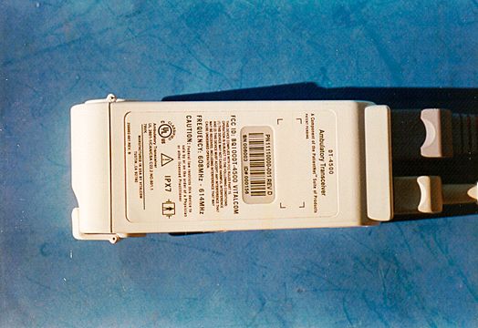
BQI01DT-4500Ambulatory Tranceiver, DT-4500
Data Critical Corporation
Click to zoom
Application Details
- Equipment Class
- TNT - Licensed Non-Broadcast Transmitter Worn on Body
- Date of Grant
- Sep 04, 2002
- Application Purpose
- Original Equipment
- Date of Application
- Jun 04, 2001
- Equipment Note
- Ambulatory Tranceiver, DT-4500
- Frequency Range
- 608.00000000 - 614.00000000
- Company
- Data Critical Corporation
- Country
- United States
Documents & Files
Document Text
Text extracted from the exhibit documents filed with the FCC. Open a document above to read the original.
Users Manual
DT-4500 Operator’s Manual 1 OPERATOR’S MANUAL FOR DT- 4500 CAUTION This instrume nt is intended for use in a hospital or clinical setting by trained and authorized personnel who are acting on the orders of a physician. Its purpose is the real-time monitoring of patients over an extended period of time. The operator should be thoroughly familiar with the information in this manual before using the inst rume nt. As wit h a ll mo nitors, t he syste m cannot re place skille d nursing ca re and pro pe r s urve illa nce . The trans mitte r po we r is limite d as re quire d by t he Fe de ral Co mmunicat io ns Co mmi ssio n a nd t hus has li mite d ra nge . To i ns ure conti nuo us mo nito ri ng, instruct the patient to remain within the area covered by the antenna system. WA RN ING DO NOT USE THE OUTPUT O F THIS DEVICE AS A SYNCHONIZATION SOURCE FOR CARDIAC DEFIBRILLATION. DELAYS IN PRESENTATION O F THE R- WAVE MAY BE AS MUCH AS 40 MILLISECONDS. DT-4500 Operator’s Manual 2 Information to User WA RN ING This equipme nt has been tested and found to comply with the limits for a CLASS B digital device, pursuant to Part 15 of the FCC Rules. These limits are designed to provide reasonable protection against harmful interference in a residential installation. This equipment generates, uses, and can radiate radio frequency energy, and, if not installed and used in accordance with the instructions contained in this manual, may cause harmful interference to radio and television communications. However, there is no guarantee that inte rfe re nce will not occ ur in a pa rtic ula r installat io n. If this equipme nt does cause harmful interference to radio or television reception, which can be determined by turning the equipment off and on, then the user is encouraged to try to correct the interference by one or more of the following measures: • Reorient or relocate the receiving antenna • Increase the separation between the equipment and the receiver • Connect the equipme nt into an outlet on a circuit different from that of the receiver • Consult the dealer or an experienced audio television technician NOTE: Connecting this device to peripheral devices that do not comply with the CLASS B requirement or using an unshielded peripheral data cable could also result in harmful interference to radio or television reception. Any changes or modifications to the device that are not expressly approved by the party responsible for compliance could void the user’s authority to operate this equipme nt. To ensure that the use of this product does not contribute to interference, it is necessary to use shielded I/O cables. Overview The DT-4500 Ambulatory Transceiver provides two-way wireless communication between analog ECG circuitry and the hospital’s data distribution network. The DT- 4500 is connected to the patient through the ECG lead circuitry and is carried on the patient in a gown or disposable paper pouch. The ambulatory transceiver converts the analog ECG patient parameters to a digital format, which is then transmitted to an Access Point transceiver. The Access Point transceiver distributes the digital data to the hospital’s data distribution network. The transceiver system includes 6 ECG leads, accurate waveform notification, data port activity, notification of radio frequency (RF) link to Access Point, battery status, attendant present switch, nurse call switch, and two I/O ports for attachment to external medical devices. Equipment Site Selection/Location The transceiver is worn by the patient and is carried either in a gown pocket or disposable paper pouch. The typical orientation is against the chest with the front facing out, which minimizes body attenuation losses. DT-4500 Operator’s Manual 3 The DT-4500 is IPX7 compliant and can be submerged in 1m of water for 30 minutes without seepage, while remaining in operating condition Operating Instructions The DT-4500 ambulatory transceiver is attached to the patient through the ECG lead system. The ECG circuitry, based on the previous DT-4000 front-end circuitry, consists of 6 lead wires and 2 I/O interfaces for external medical devices. The battery-powered transceiver enclosure is carried in a gown pocket or disposable paper pouch. The digital ECG patient parameters are transmitted to the Access Point Transceiver, which then transmits the data via Ethernet network system (cable and hub) to the hospital’s data distribution network. The 9V replaceable battery, or rechargeable battery, should last at least 48 hours. Antenna Installation The DT-4500 transmits in the 608-614 MHz frequency range. The omnidirectional antenna is a part of the lead set system, with each lead wire paired with an antenna wire. Transceiver output power and system operation requirements are defined by the FCC. The refore, it is essent ial t hat the antenna provided not be modif ied o r alte red in any way by t he end use r.
RF Exposure Info
15222 Del Amo Ave Tustin, CA 92780 (714) 546-0147 FAX (714) 546-0084 Part 95.1125 RF Safety The DT-4500 complied with the FCC requirements defined in this section. Test were conducted by Aprel Laboratories (http://www.aprel.com) under the following conditions: • Input power to the radiating leadset: 21.5dBm producing a field strength of 370mV/m at 3m • Limit to comply with: 1.6 W/Kg as averaged over any 1 gram of tissue (as stated in 2.1093 of the FCC r ules) • Max SAR reading: 0.40- 0.45 W/Kg ! within limits Note: The actual production unit has further reduced field strength of less than 200mV/m at 3 m
Test Report
Page 1 of 84 Report No.: FC01-035A VITALCOM, INC. ADDENDUM TO FC01-035 FOR THE AMBULATORY TRANSCEIVER, DT-4500 FCC PART 95 SUBPART H & FCC PART 15 SUBPART C SECTION 15.209 COMPLIANCE DATE OF ISSUE: JUNE 5, 2001 PREPARED FOR: VitalCom, Inc. 15222 Del Amo Avenue Tustin, CA 92780 PREPARED BY: Joyce Walker CKC Laboratories, Inc. 5473A Clouds Rest Mariposa, CA 95338 P.O. No.: 3008 W.O. No.: 76248 Date of test: April 18-May 11, 2001 Report No.: FC01-035A This report contains a total of 84 pages and may be reproduced in full only. Partial reproduction may only be done with the written consent of CKC Laboratories, Inc. Page 2 of 84 Report No.: FC01-035A TABLE OF CONTENTS Administrative Information ............................................................................................. 4 Summary of Results......................................................................................................... 5 Modifications Required for Compliance ......................................................................... 5 Approvals......................................................................................................................... 5 Equipment Under Test..................................................................................................... 6 Peripheral Devices ........................................................................................................... 6 Temperature and Humidity During Testing .................................................................... 6 Frequency Range Tested ................................................................................................. 6 Radiated Emissions ............................................................................................. 6 2.1033(c)(4) Type of Emission........................................................................................ 6 2.1033(c)(5) Frequency Range ........................................................................................ 6 2.1033(c)(6) Operating Power ......................................................................................... 7 2.1033(c)(7) Maximum Power Rating............................................................................. 7 2.1033(c)(8) DC Voltages ............................................................................................... 7 2.1033(c)(9) Tune-Up Procedure .................................................................................... 7 2.1046/95.115(a)(1) RF Power Output............................................................................ 8 Test Equipment Used – RF Power Output .......................................................... 8 Analyzer Bandwidth Settings During 2.1046/95.1115(a)(1) Testing.................. 9 Test Setup Photographs – RF Power Output ....................................................... 10 2.1047 Modulation Characteristics.................................................................................. 11 2.1049/95.1115(d)(2) Channel Use 608-614 MHz.......................................................... 12 95.1115(d)(2) 3 dB Bandwidth Plot .................................................................... 12 95.1115(d)(2) 20 dB Bandwidth Plot .................................................................. 12 95.1115(d)(2) 3 dB Occupied Bandwidth Plot .................................................... 13 95.1115(d)(2) 20 dB Occupied Bandwidth Plot .................................................. 13 Test Conditions – Occupied Bandwidth .............................................................. 14 Test Equipment Used – Channel Use 608-614 MHz .......................................... 14 Analyzer Bandwidth Settings During 2.1049/95.1115(d)(2) Testing ................. 14 Test Setup Photographs – Channel Use 608-614 MHz ....................................... 15 2.1051/95.1115(b)(1) & (2) Spurious Emissions at Antenna Terminal .......................... 16 Test Equipment Used - Spurious Emissions at Antenna Terminal ..................... 23 Analyzer Bandwidth Settings During 2.1051/95.1115(b)(1) & (2)Testing......... 23 Test Setup Photograph – Spurious Emissions at Antenna Terminal ................... 24 2.1053/95.1115(b)(1) Field Strength of Spurious Radiation < 960 MHz ....................... 25 Low Channel – 7-30 MHz – X Axis ................................................................... 25 Low Channel – 7-30 MHz – Y Axis ................................................................... 26 Low Channel – 7-30 MHz – Z Axis .................................................................... 27 Low Channel – 30-1000 MHz – X Axis ............................................................. 28 Low Channel – 30-1000 MHz – Y Axis ............................................................. 30 Low Channel – 30-1000 MHz – Z Axis .............................................................. 32 Mid Channel – 7-30 MHz – X Axis .................................................................... 34 Page 3 of 84 Report No.: FC01-035A Mid Channel – 7-30 MHz – Y Axis .................................................................... 35 Mid Channel – 7-30 MHz – Z Axis..................................................................... 36 Mid Channel – 30-1000 MHz – X Axis .............................................................. 37 Mid Channel – 30-1000 MHz – Y Axis .............................................................. 39 Mid Channel – 30-1000 MHz – Z Axis............................................................... 41 High Channel – 7-30 MHz – X Axis................................................................... 43 High Channel – 7-30 MHz – Y Axis................................................................... 44 High Channel – 7-30 MHz – Z Axis ................................................................... 45 High Channel – 30-1000 MHz – X Axis............................................................. 4…
Text truncated - open the document above for the full version.
Test Setup Photos
Front View Back View Direct Connect
Contact Information
Applicant
Sharon Untz
Non-Technical Contact
CKC Laboratories, Inc.Joyce Walker
[email protected]1-800-500-4362
Technical Specifications
| # | Rule Parts | Frequency Range | Power Output | Emission | Tolerance |
|---|---|---|---|---|---|
| 1 | 95H | 608 MHz - 614 MHz | 3.54 mW | 230KF7D | 50.0000000000 ppm |
Other Applications from Data Critical Corporation

BQI02DR-10110
Mar 23, 2003WMTS OPENNET LAN
Equipment Class
TNB - Licensed Non-Broadcast Station Transmitter
BQI02DR-10100
Dec 12, 2002WMTS OPENNET LAN
Equipment Class
TNB - Licensed Non-Broadcast Station Transmitter
BQI02DT-7000
Dec 08, 2002PATIENTNET
Equipment Class
TNB - Licensed Non-Broadcast Station Transmitter
BQI99DT-5100
Sep 03, 2002V-Link II (one way wireless communication)
Equipment Class
DXX - Part 15 Low Power Communication Device Transmitter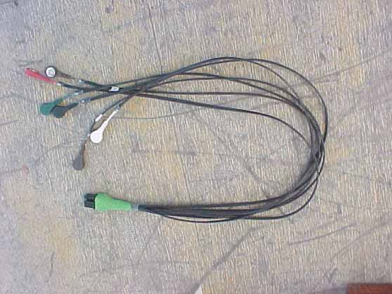
BQIOODT-4500
Aug 13, 2002OpenNet Transceiver
Equipment Class
DXX - Part 15 Low Power Communication Device Transmitter