BQIOODT-4500OpenNet Transceiver
Data Critical Corporation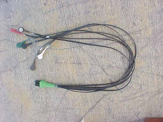
Click to zoom
Application Details
- Equipment Class
- DXX - Part 15 Low Power Communication Device Transmitter
- Date of Grant
- Aug 13, 2002
- Application Purpose
- Original Equipment
- Date of Application
- Jun 06, 2000
- Equipment Note
- OpenNet Transceiver
- Frequency Range
- 608.70000000 - 612.96500000
- Company
- Data Critical Corporation
- Country
- United States
Documents & Files
Document Text
Text extracted from the exhibit documents filed with the FCC. Open a document above to read the original.
Users Manual
DT-4500 Operator’s Manual 1 OPERATOR’S MANUAL FOR DT- 4500 CAUTION This instrument is intended for use in a hospital or clinical setting by trained and authorized personnel who are acting on the orders of a physician. Its purpose is the real-time monitoring of patients over an extended period of time. The operator should be thoroughly familiar with the information in this manual before using the instrument. As with all monitors, the system cannot replace skilled nursing care and proper surveillance. The transmitter power is limited as required by the Federal Communications Commission and thus has limited range. To insure continuous monitoring, instruct the patient to remain within the area covered by the antenna system. WARNING DO NOT USE THE OUTPUT OF THIS DEVICE AS A SYNCHONIZATION SOURCE FOR CARDIAC DEFIBRILLATION. DELAYS IN PRESENTATION OF THE R-WAVE MAY BE AS MUCH AS 40 MILLISECONDS. DT-4500 Operator’s Manual 2 Information to User WARNING This equipment has been tested and found to comply with the limits for a CLASS B digital device, pursuant to Part 15 of the FCC Rules. These limits are designed to provide reasonable protection against harmful interference in a residential installation. This equipment generates, uses, and can radiate radio frequency energy, and, if not installed and used in accordance with the instructions contained in this manual, may cause harmful interference to radio and television communications. However, there is no guarantee that interference will not occur in a particular installation. If this equipment does cause harmful interference to radio or television reception, which can be determined by turning the equipment off and on, then the user is encouraged to try to correct the interference by one or more of the following measures: • Reorient or relocate the receiving antenna • Increase the separation between the equipment and the receiver • Connect the equipment into an outlet on a circuit different from that of the receiver • Consult the dealer or an experienced audio television technician NOTE: Connecting this device to peripheral devices that do not comply with the CLASS B requirement or using an unshielded peripheral data cable could also result in harmful interference to radio or television reception. Any changes or modifications to the device that are not expressly approved by the party responsible for compliance could void the user’s authority to operate this equipment. To ensure that the use of this product does not contribute to interference, it is necessary to use shielded I/O cables. Overview The DT-4500 Ambulatory Transceiver provides two-way wireless communication between analog ECG circuitry and the hospital’s data distribution network. The DT- 4500 is connected to the patient through the ECG lead circuitry and is carried on the patient in a gown or disposable paper pouch. The ambulatory transceiver converts the analog ECG patient parameters to a digital format, which is then transmitted to an Access Point transceiver. The Access Point transceiver distributes the digital data to the hospital’s data distribution network. The transceiver system includes 6 ECG leads, accurate waveform notification, data port activity, notification of radio frequency (RF) link to Access Point, battery status, attendant present switch, nurse call switch, and two I/O ports for attachment to external medical devices. Equipment Site Selection/Location The transceiver is worn by the patient and is carried either in a gown pocket or disposable paper pouch. The typical orientation is against the chest with the front facing out, which minimizes body attenuation losses. DT-4500 Operator’s Manual 3 The DT-4500 is IPX7 compliant and can be submerged in 1m of water for 30 minutes without seepage, while remaining in operating condition Operating Instructions The DT-4500 ambulatory transceiver is attached to the patient through the ECG lead system. The ECG circuitry, based on the previous DT-4000 front-end circuitry, consists of 6 lead wires and 2 I/O interfaces for external medical devices. The battery-powered transceiver enclosure is carried in a gown pocket or disposable paper pouch. The digital ECG patient parameters are transmitted to the Access Point Transceiver, which then transmits the data via Ethernet network system (cable and hub) to the hospital’s data distribution network. The 9V replaceable battery, or rechargeable battery, should last at least 48 hours. Antenna Installation The DT-4500 transmits in the 608-614 MHz frequency range. The omnidirectional antenna is a part of the lead set system, with each lead wire paired with an antenna wire. Transceiver output power and system operation requirements are defined by the FCC. Therefore, it is essential that the antenna provided not be modified or altered in any way by the end user.
Attestation Statements
1 Worst Case Transmit Duty Cycle for WIT608 The duty cycle derating factor used in the calculation of average radiated limits (per 15.209 for frequencies above 1GHz) is described below. This factor was calculated by first determining the worst case scenario for system operation - worst case being defined as the scenario when the WIT608 would be transmitting the longest period during a dwell. This worst case operating scenario is as follows: 1) data flow is almost completely unidirectional (that is, one radio is relaying a large amount of data to the other radio with only synchronization data being passed back the other direction) 2) The amount of data being fed to the sending radio is exactly portioned out to fit the maximum packet size allowable (252 bytes). The radio cannot send more than 252 bytes on a single channel – additional data must be sent on the next hop. For this example, a remote unit is transferring monitoring data to a base unit. Maximum transmit time by Remote on a single channel: = 252 bytes * 8 bits/byte * (1/230.4Kbps) = 8.75ms Hop duration (dwell time) for this scenario is 35.28ms. Given that we have 32 channels in our hop set, it takes 1.12896 seconds to go through the entire hop table and repeat a transmission on the same channel. Therefore, only 8.75 milliseconds worth of data can be transmitted on a single channel in any 100 milliseconds time period. The transmission duty cycle correction factor is then calculated as: 20 * Log 10 (8.75ms/100ms) = -21.2 dB A 35% duty cycle was assumed during the testing, which is the hop duration.
ID Label/Location Info
15222 Del Amo Ave Tustin, CA 92780 (714) 546-0147 FAX (714) 546-0084
Test Report
FCC ID: BQIOODT-4500 Report No.: B00518D1 114 OLINDA DRIVE, BREA, CALIFORNIA 92823 PHONE: (714) 579-0500 FAX: (714) 579-1850 Page 2 of 15 TABLE OF CONTENTS Section / Title PAGE GENERAL REPORT SUMMARY 4 SUMMARY OF TEST RESULTS 4 1. PURPOSE 5 2. ADMINISTRATIVE DATA 6 2.1 Location of Testing 6 2.2 Traceability Statement 6 2.3 Cognizant Personnel 6 2.4 Date Test Sample was Received 6 2.5 Disposition of the Test Sample 6 2.6 Abbreviations and Acronyms 6 3. APPLICABLE DOCUMENTS 7 4. Description of Test Configuration 8 4.1 Description of Test Configuration - EMI 8 4.1.1 Cable Construction and Termination 9 5. LISTS OF EUT, ACCESSORIES AND TEST EQUIPMENT 10 5.1 EUT and Accessory List 10 5.2 EMI Test Equipment 11 6. TEST SITE DESCRIPTION 12 6.1 Test Facility Description 12 6.2 EUT Mounting, Bonding and Grounding 12 7. Test Procedures 13 7.1 Radiated Emissions (Spurious and Harmonics) Test 13 7.3 RF Band Edges 14 8. CONCLUSIONS 15 FCC ID: BQIOODT-4500 Report No.: B00518D1 114 OLINDA DRIVE, BREA, CALIFORNIA 92823 PHONE: (714) 579-0500 FAX: (714) 579-1850 Page 3 of 15 LIST OF APPENDICES APPENDIX TITLE A Modifications to the EUT B Additional Models Covered Under This Report C Diagrams, Charts and Photos • Test Setup Diagrams • Radiated Emissions Photos • Antenna and Effective Gain Factors D Data Sheets LIST OF FIGURES FIGURE TITLE 1 Conducted Emissions Test Setup 2 Plot Map And Layout of Test Site FCC ID: BQIOODT-4500 Report No.: B00518D1 114 OLINDA DRIVE, BREA, CALIFORNIA 92823 PHONE: (714) 579-0500 FAX: (714) 579-1850 Page 4 of 15 GENERAL REPORT SUMMARY This electromagnetic emission test report is generated by Compatible Electronics Inc., which is an independent testing and consulting firm. The test report is based on testing performed by Compatible Electronics personnel according to the measurement procedures described in the test specifications given below and in the "Test Procedures" section of this report. The measurement data and conclusions appearing herein relate only to the sample tested and this report may not be reproduced in any form unless done so in full with the written permission of Compatible Electronics. This report must not be used to claim product endorsement by NVLAP or any other agency of the U.S. Government. Device Tested: Medical Transceiver Model: DT4500 S/N: N/A Product Description: See Expository Statement. Modifications: The EUT was not modified during the testing. Manufacturer: Vitalcom 15222 Del Amo Avenue Tustin, California 92780 Test Dates: May 18 and 26, 2000 Test Specifications: EMI requirements CFR Title 47, Part 15 Subpart C, Sections 15.205, 15.209, and 15.242 Test Procedure: ANSI C63.4: 1992 Test Deviations: The test procedure was not deviated from during the testing. SUMMARY OF TEST RESULTS TEST DESCRIPTION RESULTS 1 Conducted RF Emissions, 450 kHz - 30 MHz This test was not performed because the EUT is powered by a nine volt battery. 2 Radiated RF Emissions, 10 kHz – 6130 MHz Complies with the limits of CFR Title 47, Part 15, Subpart C, sections 15.205, 15.209 and 15.242 FCC ID: BQIOODT-4500 Report No.: B00518D1 114 OLINDA DRIVE, BREA, CALIFORNIA 92823 PHONE: (714) 579-0500 FAX: (714) 579-1850 Page 5 of 15 1. PURPOSE This document is a qualification test report based on the Electromagnetic Interference (EMI) tests performed on the Medical Transceiver Model: DT4500. The EMI measurements were performed according to the measurement procedure described in ANSI C63.4: 1992. The tests were performed in order to determine whether the electromagnetic emissions from the equipment under test, referred to as EUT hereafter, are within the specification limits defined by CFR Title 47, Part 15, Subpart C, sections 15.205, 15.209, and 15.242. FCC ID: BQIOODT-4500 Report No.: B00518D1 114 OLINDA DRIVE, BREA, CALIFORNIA 92823 PHONE: (714) 579-0500 FAX: (714) 579-1850 Page 6 of 15 2. ADMINISTRATIVE DATA 2.1 Location of Testing The EMI tests described herein were performed at the test facility of Compatible Electronics, 114 Olinda Drive, Brea, California 92823. 2.2 Traceability Statement The calibration certificates of all test equipment used during the test are on file at the location of the test. The calibration is traceable to the National Institute of Standards and Technology (NIST). 2.3 Cognizant Personnel Vitalcom Gus Testa RF Engineer Compatible Electronics Inc. Kyle Fujimoto Test Engineer Scott McCutchan Lab Manager 2.4 Date Test Sample was Received The test sample was received on May 18, 2000. 2.5 Disposition of the Test Sample The test sample was returned to Vitalcom on May 18, 2000. 2.6 Abbreviations and Acronyms The following abbreviations and acronyms may be used in this document. RF Radio Frequency EMI Electromagnetic Interference EUT Equipment Under Test P/N Part Number S/N Serial Number HP Hewlett Packard ITE Information Technology Equipment CML Corrected Meter Limit LISN Line Impedance Stabilization Network FCC ID: BQIOODT-4500 Report No.: B00518D1 114 OLINDA DRIVE, BREA, CALIFORNIA 92823 PHONE: (714) 579-0500 FAX: (714) 579-1850 Page 7 of 15 3. APPLICABLE DOCUMENTS The following documents are referenced or used in the preparation of this EMI Test Report. SPEC TITLE CFR Title 47, Subpart C. FCC Rules – Radio frequency devices (including digital devices) – Intentional Radiators ANSI C63.4 1992 Methods of measurement of radio-noise emissions from low-voltage electrical and electronic equipment in the range of 9 kHz to 40 GHz. FCC ID: BQIOODT-4500 Report No.: B00518D1 114 OLINDA DRIVE, BREA, CALIFORNIA 92823 PHONE: (714) 579-0500 FAX: (714) 579-1850 Page 8 of 15 4. DESCRIPTION OF TEST CONFIGURATION 4.1 Description of Test Configuration - EMI Specifics of the EUT and Peripherals Tested The Medical Transceiver Model: DT4500 (EUT) was connected to a laptop and six ECG leads via its serial and ECG ports, respectively.. The EUT is powered by a nine volt battery. The EUT was tested in three orthogonal axis with the low, middle, and high channels tested. The EUT was conti…
Text truncated - open the document above for the full version.
Contact Information
Applicant
Sharon Untz
Test Firm
Compatible ElectronicsScott McCutchan
714-579-0500Fax: 714-579-1850
Technical Specifications
| # | Rule Parts | Frequency Range | Power Output |
|---|---|---|---|
| 1 | 15C | 608.7 MHz - 612.965 MHz | - |
Other Applications from Data Critical Corporation

BQI02DR-10110
Mar 23, 2003WMTS OPENNET LAN
Equipment Class
TNB - Licensed Non-Broadcast Station Transmitter
BQI02DR-10100
Dec 12, 2002WMTS OPENNET LAN
Equipment Class
TNB - Licensed Non-Broadcast Station Transmitter
BQI02DT-7000
Dec 08, 2002PATIENTNET
Equipment Class
TNB - Licensed Non-Broadcast Station Transmitter
BQI01DT-4500
Sep 04, 2002Ambulatory Tranceiver, DT-4500
Equipment Class
TNT - Licensed Non-Broadcast Transmitter Worn on Body
BQI99DT-5100
Sep 03, 2002V-Link II (one way wireless communication)
Equipment Class
DXX - Part 15 Low Power Communication Device Transmitter