BQM22802332Broadcast Television Transmitter
Acrodyne Industries, Inc.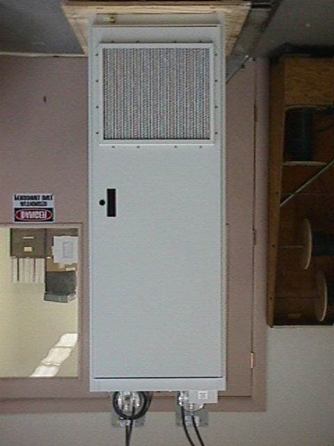
Click to zoom
Application Details
- Equipment Class
- TBC - Licensed Broadcast Station Transmitter
- Date of Grant
- Sep 23, 1999
- Application Purpose
- Original Equipment
- Date of Application
- Jun 01, 1999
- Equipment Note
- Broadcast Television Transmitter
- Frequency Range
- 174.00000000 - 216.00000000
- Company
- Acrodyne Industries, Inc.
- Country
- United States
Documents & Files
Document Text
Text extracted from the exhibit documents filed with the FCC. Open a document above to read the original.
Users Manual
TRH1KE_3.doc3.28-Jul-99 i NOTICE EQUIPMENT LOST OR DAMAGED IN TRANSIT When delivering the equipment to you , the driver or carrier’s agent will present a receipt for your signature. Do not sign it until you have (a) inspected the containers for visible signs of damage and (b) counted the containers and compared with the amount shown on the shipping papers. If a shortage or evidence of damage is noted , insist that notation to that effect be made on the shipping papers before you sign them. After receiving the equipment, unpack it and inspect thoroughly for concealed damage. If concealed damage is discovered, immediately notify the carrier, confirming the notification in writing, and secure an inspection report. Loss or damage in transit is not covered by Acrodyne. You must file a claim with the carrier. All shortages should be reported to: ACRODYNE INDUSTRIES, INC. FIELD SERVICE DEPARTMENT 516 TOWNSHIP LINE ROAD BLUE BELL, PA 19422 USA TELEPHONE: (215) 542-7000 OR (800) 523- 2596 (OUTSIDE PA) FAX NO: (215) 540-5837 E-MAIL: [email protected] INTERNET: ACRODYNE.COM SAFETY CONSIDERATIONS Through out Acrodyne instruction manuals the following terms designate hazards and special considerations for proper equipment operation. WARNING “WARNING” designates a personnel hazard. Personal injury may result if good operating practice and the operators manual are not followed. CAUTION “CAUTION” designates a hazard which may damage or destroy the equipment if good operating practice and the operators manual are not followed. NOTE “NOTE” designates instructions which must be followed to assure operation as specified WARNING Hazardous and lethal voltages are present in this equipment when connected to AC mains voltages. Do not attempt any adjustments of this equipment that requires opening covers or panels without first removing and locking-out AC mains feeds and using the grounding sticks provided to discharge the power supply capacitors. Never disable interlocks for access panels to areas containing high voltage. The interlocks are there for your protection. Do not perform maintenance or service this equipment when alone. Observe safety procedures at all times. Read this equipment manual before attempting operation of this equipment; know your equipment. High pressure blowers may be used in this equipment. Such blowers produce high sound levels. Long term exposure to these levels may adversely affect hearing. Always use hearing protection when working around operating equipment. Keep all blowers intake guards, filters, etc. in place. The rotating impeller will suck in lose clothing, long hair with potentially fatal results. The transmitter produces RF radiation that may be harmful. Ensure that all RF connections within the transmitter and from the transmitter RF output through externally connected coaxial components to the antenna or terminating load are fully tightened. WARNING The RF power transistors used in this transmitter may contain beryllium oxide, which is hazardous if its dust is inhaled, or is contacted by broken skin. Use caution when handling RF power transistors. If damage should occur to a transistor the part should be handled with gloves and sealed in a plastic bag. FAULT PROTECTION CIRCUITS The equipment described in this manual contains protective circuits and mechanisms which provide fault protection to minimize the effects of external and internal fault conditions. Proper maintenance and operational verification of these circuits and mechanism must be performed routinely to assure that the fault protection circuits are functioning properly. EQUIPMENT REPAIR After the equipment warranty expires, return of the unit to the factory for repair is recommended. If you wish to return an Acrodyne product for repair, call the Customer Service Department to notify them of your intent. Please include a written description of the problem you have encountered, the model number TRH1KE_3.doc3.28-Jul-99 ii and the serial number with the unit you return. If you wish to attempt to repair the unit yourself, note that repairs should be made only by those with experience on transistor circuits and printed circuitry. Incorrect procedures can damage a unit beyond repair. Order replacement semiconductors from Acrodyne. Standard passive components may be purchased from electronic supply houses. Refer to the parts list sections for parts information. NOTE Acrodyne reserves the right to change specifications, components or design from that stated herein or to discontinue models at any time without notice and without incurring obligation. TRH1KE_3.doc3.28-Jul-99 1 1.0 GENERAL INFORMATION 1.1 INTRODUCTION The Acrodyne TRH/1KE Television Transmitter broadcasts C3F visual and F3E aural emissions on any single television channel between 174 and 230 MHz at a transmitter output level of 1 kilowatt peak of sync visual and one hundred watts average aural power. The units uses intermediate frequency (IF) modulation and combined visual and aural carrier amplification throughout. The entire transmitter is contained within a single 19 inch wide cabinet. 1.2 DESCRIPTION Refer to the block diagram included with the drawing package. The TRH/1KE may be broken down into three major sections. They are 1) Exciter, 2) Intermediate Power Amplifier (IPA) and 3) Final Power Amplifier (PA) and associated control circuits and power supplies. The transmitter’s program video signal path begins with the Video Sync Automatic Gain Control (AGC) printed circuit board within the Video Processor Chassis. Video AGC is used to stabilize the program video signal sync region against variations in the signal supplied to the transmitter. The Video AGC output signal is then connected to the Video Corrector printed circuit board within the processor chassis. The Video Corrector is used to provide adjustment of the transmitter differential gain/differential phase characteristics and for sync pulse amplitude adjustment. The processed video signal fr…
Text truncated - open the document above for the full version.
Users Manual
A A B B C C D D E E F F G G H H I I J J 1010 99 88 77 66 55 44 33 22 11 120/240V IN CB3-2 TB1100/G TB1000/N TB1100 P21-5 P21-1/J1302-7 J6-2 J6-3 P21-17 J1302-23 J1302-11 J1302-6 J1302-8 A17TB1-4 P81 IF PROCESSOR DRAWER P901-11 TB1100/GGROUND FWD AUR SAMPLE FWD VIS SAMPLE 24(15) VDC IN P901-12 RF CONVERTER /EXCITER DRAWER TB1100/G GROUND EXCITER ENABLE IN VIDEO SENSE OUT RF DISABLE OUT REMOTE PWR UP REMOTE PWR DOWN +12 VDC OUT +24 VDC OUT RF CONVERTER STATUS RF DISABLE IN GROUND (SEE NOTE 1) 12 VDC IN TB1100 P21-18 CODE ID BOX (SEE NOTE 1) GROUND P83 P11-3 J5-2 J1302-1 J4-2/J901-11 J1302-13 J4-4 J4-3/J901-12 J5-3 TB1100/G TB1100/G VIDEO SENSE IN SYSTEM SHUTDOWN TO SW/O REM TX OFF REM TX ON EXCITER ENABLE INH REM STATUS RF ENABLE REM STATUS VIDEO SENSE VIDEO SENSE IND TO SW/O SYSTEM START INHIBIT OUT IPA START COMMAND OUT HPA READY IND IN AGC SAMPLE VSWR FAULT OUT +12 VDC OUT +12 VDC OUT +12 VDC OUT (IN) NOTE 1 HPA OVERCURRENT FAULT TX READY IND OVERRIDE EXCITER ENABLE GROUND GROUND GROUND GROUND P901-15 P83-1 HPA START COMMAND OUT CONTROL LOGIC CHASSIS HPA START COMMAND OUT +12 VDC OUT IPA READY IND IN HPA START COMMAND OUT TX READY IND OVERRIDE EXC ENABLE STATUS TO SW/O TB1100/G TB1100/G REM TELEM FWD VIS REM TELEM FWD AUR REM TELEM REFL EXT EQUIP RF DISABLE HPA OVERCURRENT FAULT 12V OUT FOR SHARED SW/O USE J1302-4 J6-4 J6-5 P11-2 P901-3 P45-7 P901-1 P41-11/J1302-17 PM1-NC P11-10 J1302-12 J1302-9 TB1303-2 J901-6 P41-6 J1302-10/J901-15 J1302-24 J1302-25 P45-6 A11TB2-1 A11TB2-3 TB1100 TB1100 +28V IN +28V IN GND GND 1 WATT PANEL CB3-2 +24 VDC OUT 3 TB1 4 TB1000 GROUND +24 VDC PS PN 23206425 REF A17 2 5 1 TB1100/G P81-1 6 7 AC LINE IN AC LINE IN - ACRODYNE INDUSTRIES, INC. 22513378 Monday, May 17, 199916 B 516 TOWNSHIP LINE ROAD BLUE BELL, PA. 19422-2797 TEL 215-542-7000 FAX 215-540-5837 CABINET WIRING DIAGRAM:2x650 WATT AMPLIFIER VHF 51336 DRAWN BY: KPOOLE DATE: 3/10/99 APPROVED BY: DATE: CHECKED BY: DATE: NEXT ASSY: Size Scale CAGE Code DWG NO Rev Sheet of A 1 2 3 4 5 6 7 8 9 P21 1 2 3 4 5 6 7 8 9 10 11 12 13 14 15 16 17 18 19 20 21 22 23 24 25 26 27 28 29 30 31 32 33 34 35 36 37 TB46 1 2 3 4 P11 1 2 3 4 5 6 7 8 9 10 11 12 13 14 15 16 1 2 3 4 5 6 7 8 9 A A B B C C D D E E F F G G H H I I J J 1010 99 88 77 66 55 44 33 22 11 P45-8 P41-6/J12-2 P41-7/J12-3 A11TB1-5 TB1100 P41-11/J12-4 A11E6/A11TB1-10 A11E6 A11E8/A11TB1-11 A11E8 TB1100 TB1100 TB1100 TB1100 P21-19/P42-6 P21-14/P42-11 650 WATT AMPLIFIER DRAWER 1 P45-7/P42-7 A11E4 TB1100 TB1100 A11E2/A11TB1-7 TB1100 P45-8 A11E4/A11TB1-8 TB1100 650 WATT AMPLIFIER DRAWER 2 GROUND PS CONTROL (-) +12V INPUT AMPL START IN PS CONTROL (+) GROUND PS CONTROL (-) +12V INPUT AMPL START IN PS CONTROL (+) AMPL READY OUT GROUND GROUND +28VDC INPUT +28VDC INPUT GROUND GROUND +28VDC INPUT +28VDC INPUT GROUND GROUND +28VDC INPUT +28VDC INPUT GROUND GROUND +28VDC INPUT +28VDC INPUT A11TB1-12 A11E2 TB1100 INTERMEDIATE AMPLIFIER DRAWER TB1100/G TB1100/G TB1100/G TB1100/G P21-20 P41-5/P42-5 A11TB2-1 P21-11/P41-7 A11TB2-2 A11TB2-3 A11TB2-4 AMPL READY OUT - ACRODYNE INDUSTRIES, INC. 22513378 Friday, May 14, 199926 B 516 TOWNSHIP LINE ROAD BLUE BELL, PA. 19422-2797 TEL 215-542-7000 FAX 215-540-5837 CABINET WIRING DIAGRAM:2x650 WATT AMPLIFIER VHF 51336 DRAWN BY: KPOOLE DATE: 3/10/99 APPROVED BY: DATE: CHECKED BY: DATE: NEXT ASSY: Size Scale CAGE Code DWG NO Rev Sheet of A B P41 1 2 3 4 5 6 7 8 9 10 11 12 13 14 15 16 P51L 1- 2- 2+ 1+ P51R 1- 2- 2+ 1+ P45 1 2 3 4 5 6 7 8 9 10 11 12 13 14 15 16 P52R 1- 2- 2+ 1+ P52L 1- 2- 2+ 1+ P42 1 2 3 4 5 6 7 8 9 10 11 12 13 14 15 16 A A B B C C D D E E F F G G H H I I J J 1010 99 88 77 66 55 44 33 22 11 E1 E3 E5 E7 E2 E4 E6 E8 POWER SUPPLY CONTROLLER & FUSE BOARD ref A11 L1 L2 V+ V- 28V POWER SUPPLY ref PS1 CB1-2 CB1-4 TB1100/G TB1100/G PS1-V+ PS1-V+ PS2-V+ PS2-V+ P51L-1+/P51L-2+ P51R-1+/P51R-2+ P52L-1+/P52L-2+ P52R-1+/P52R-2+ A11E1 J4-5 J4-6 J4-8 J4-9 P41-8 J4-7 P51L-1+ P51R-1+ P52R-1+ A11E3 P45-10\TB46-1 P45-14 J1/P1 PS1P1/PS2P1 * These connections are made at the sub-assembly level, 22212570. Shown here for clarity. * These connections are made at the sub-assembly level. Shown here for clarity. TB1100 P52L-1+ *CABLE ASSY 22212570 TO A11J1 F6 AMPL #1L (V+) SAMPLE PS1 ENABLE PS1 CURRENT MON PS1 S+ PS1 S- PS1 S+ PS2 S+ PS2 S+ PS2 ENABLE PS2 CURRENT MON PS2 S- AC INPUT AC INPUT AC INPUT GROUND GROUND +28 VDC OUT TB1100 J4-10 F5 AMPL #1R (V+) SAMPLE F4 AMPL #2L (V+) SAMPLE F3 AMPL #2R (V+) SAMPLE L1 L2 V+ V- 28V POWER SUPPLY ref PS2 CB2-2 CB2-4 TB1100/G TB1100/G A11E5 A11E7 * These connections are made at the sub-assembly level. Shown here for clarity. *CABLE ASSY 22212570 TO A11J1 AC INPUT AC INPUT AC INPUT GROUND GROUND +28 VDC OUT (SEE NOTE 2) 2: THIS POWER SUPPLY IS ONLY USED IN DUAL POWER SUPPLY CONFIGURATION AND IS AN OPTION TO THE SYSTEM. P42-8 P45-16 P45-15\TB46-2 CB2-6 (FOR 3PHASE ONLY) CB1-6 (FOR 3PHASE ONLY) L3 L3 DB25 CONN FOR HC40 ONLY(SINGLE PS CONFIGURATION ONLY) P1 P2 P1 NOTES P1 P2 - ACRODYNE INDUSTRIES, INC. 22513378 Friday, May 14, 199936 B 516 TOWNSHIP LINE ROAD BLUE BELL, PA. 19422-2797 TEL 215-542-7000 FAX 215-540-5837 CABINET WIRING DIAGRAM:2x650 WATT AMPLIFIER VHF 51336 DRAWN BY: KPOOLE DATE: 3/10/99 APPROVED BY: DATE: CHECKED BY: DATE: NEXT ASSY: Size Scale CAGE Code DWG NO Rev Sheet of B C TB2 1 2 3 4 5 6 1 2 3 4 5 6 7 8 9 10 11 12 13 14 15 16 17 18 19 20 21 22 23 24 25 1 2 3 4 5 6 7 8 9 1 2 3 4 5 6 7 8 9 1 2 3 4 5 6 7 8 9 1 2 3 4 5 6 7 8 9 TB1 1 2 3 4 5 6 7 8 9 10 11 12 13 14 15 A A B B C C D D E E F F G G H H I I J J 1010 99 88 77 66 55 44 33 22 11 TELEMETRYSTATUSCOMMAND TB1100/GTB1100/GTB1100/G P21-30 P21-31 P21-32 A11TB1-1 A11TB1-2 A11TB1-3 A11TB1-4 A11TB1-6 A11TB1-13 GROUNDGROUNDGROUND FWD VISUAL PWR REFL PWR FWD AURAL PWR PS1 CURRENT MON PS2 CURRENT MON P21-6 P21-8 RF ENABLED VIDEO SENSED P11-6 P11-7 P21-3 P21-4 POWER RAISE POWER LOWER TX OFF TX ONF6 (AMPL #1L) VOLTS P21-9/TB2-5 P21-2 P11-3 TB1100/G P11-16 P21-37 P21-24 P11-4 P21-14 J1302 SWITCHOVER SYSTEM INTERFACE P11-15 P21-22 P21-23 TB1100 P21-34 GROUND …
Text truncated - open the document above for the full version.
Cover Letter(s)
1 July 30, 1999 FEDERAL COMMUNICATIONS COMMISSION Chief Mass Media Bureau c/o Authorization and Evaluation Division 7435 Oakland Mills Road Columbia, MD 21046 RE: FCC ID BQM22802332 Dear Sirs: This letter forms a request for waiver of FCC Rules Section 74.750(c)(2) to allow measurement of the mean power of the spurious emissions, in lieu of peak, as outlined in the letters from Thomas P. Stanley, Chief Engineer, FCC to Dane Erickson, Hammett and Edison and Robert L. Cutts, FCC to Timothy P. Hulick, Acrodyne, for the above referenced certification submittal. Regards, William F. Soreth, System Design WFS/mgd 2 July 30, 1999 FEDERAL COMMUNICATIONS COMMISSION Authorization and Evaluation Services 7435 Oakland Mills Road Columbia, MD 21046 Dear Sirs: Enclosed is a submission for certification of an ACRODYNE TRH/1KE television transmitter. Regards William F. Soreth Systems Engineer Enclosures
External Photos
APPLICATION FOR CERTIFICATION FCC IDENTIFICATION NUMBER:BQM22802332 DATE:July 30, 1999 11 APPLICABLE FCC PARAGRAPH:2.1033(c) SUB-PARAGRAPH:(12) PARAGRAPH TITLE:EQUIPMENT PHOTOGRAPHS ƒƒƒƒƒƒƒƒƒƒƒƒƒƒƒƒƒƒƒƒƒƒƒƒƒƒƒƒƒƒƒƒƒƒƒƒƒƒƒƒƒƒƒƒƒƒƒƒƒƒƒƒƒƒƒƒƒƒƒƒƒƒƒƒ APPLICATION FOR CERTIFICATION FCC IDENTIFICATION NUMBER:BQM22802332 DATE:July 30, 1999 12 APPLICABLE FCC PARAGRAPH:2.1033(c) SUB-PARAGRAPH:(12) PARAGRAPH TITLE:EQUIPMENT PHOTOGRAPHS ƒƒƒƒƒƒƒƒƒƒƒƒƒƒƒƒƒƒƒƒƒƒƒƒƒƒƒƒƒƒƒƒƒƒƒƒƒƒƒƒƒƒƒƒƒƒƒƒƒƒƒƒƒƒƒƒƒƒƒƒƒƒƒƒ
ID Label/Location Info
APPLICATION FOR CERTIFICATION FCC IDENTIFICATION NUMBER:BQM22802332 DATE:May 25, 2001 1 APPLICABLE FCC PARAGRAPH:2.1033(c) SUB-PARAGRAPH:(11) PARAGRAPH TITLE:EQUIPMENT IDENTIFICATION PLATE ──────────────────────────────────────────────────────────────── FCC ID: BQM22802332 TRH/1KE ACRODYNE INDUSTRIES, INC APPLICATION FOR CERTIFICATION FCC IDENTIFICATION NUMBER:BQM22802332 DATE:May 25, 2001 2 APPLICABLE FCC PARAGRAPH:2.1033(c) SUB-PARAGRAPH:(12) PARAGRAPH TITLE:EQUIPMENT PHOTOGRAPHS ──────────────────────────────────────────────────────────────── APPLICATION FOR CERTIFICATION FCC IDENTIFICATION NUMBER:BQM22802332 DATE:May 25, 2001 3 APPLICABLE FCC PARAGRAPH:2.1033(c) SUB-PARAGRAPH:(12) PARAGRAPH TITLE:EQUIPMENT PHOTOGRAPHS ────────────────────────────────────────────────────────────────
Operational Description
TRH1KE_3.doc3.28-Jul-99 1 1.0 GENERAL INFORMATION 1.1 INTRODUCTION The Acrodyne TRH/1KE Television Transmitter broadcasts C3F visual and F3E aural emissions on any single television channel between 174 and 230 MHz at a transmitter output level of 1 kilowatt peak of sync visual and one hundred watts average aural power. The units uses intermediate frequency (IF) modulation and combined visual and aural carrier amplification throughout. The entire transmitter is contained within a single 19 inch wide cabinet. 1.2 DESCRIPTION Refer to the block diagram included with the drawing package. The TRH/1KE may be broken down into three major sections. They are 1) Exciter, 2) Intermediate Power Amplifier (IPA) and 3) Final Power Amplifier (PA) and associated control circuits and power supplies. The transmitter’s program video signal path begins with the Video Sync Automatic Gain Control (AGC) printed circuit board within the Video Processor Chassis. Video AGC is used to stabilize the program video signal sync region against variations in the signal supplied to the transmitter. The Video AGC output signal is then connected to the Video Corrector printed circuit board within the processor chassis. The Video Corrector is used to provide adjustment of the transmitter differential gain/differential phase characteristics and for sync pulse amplitude adjustment. The processed video signal from the Video Processor Chassis is routed to the Exciter Chassis and the modulator circuit where it amplitude modulates the visual intermediate frequency carrier operating at 45.75 MHz CCIR M/38.9 MHz CCIR G. The modulated carrier is then passed through a SAW (Surface Acoustic Wave) filter with group delay correction to provide the proper lower sideband and group delay performance. The transmitter’s program aural signal path begins directly with the Exciter Chassis and the aural modulator circuit. Both balanced and unbalanced aural inputs are provided. These inputs frequency modulate an aural carrier, operating at 4.5 MHz CCIR M/5.5 MHz CCIR G, that is then converted to an IF carrier frequency of 45.75 MHz CCIR M/33.4 MHz CCIR G. The three signal inputs to the IF Processor Chassis connect first to the Aural Corrector Board where signals for correction of vision to sound cross- modulation are generated. The three signals out of the Aural Corrector Board are connected to the Intermodulation (IM)/Incidental Carrier Phase Modulation (ICPM) Corrector board where they act to provide correction for inband intermodulation distortion and incidental carrier phase modulation. The separate vision and sound IF carrier outputs from this board are routed to the Visual/Aural Combiner board and mixed to create a composite IF signal. The composite IF signal is then connected to the IF Linearity Corrector circuit board, also within the IF Processor Chassis. The IF Linearity Corrector board contains a double break point diode network that is used to correct primarily for transmitter luminance (low frequency) non-linearities. The IF Linearity Corrector output is the output of the IF Processor Chassis. The IF Processor Chassis output is connected back to the Exciter Chassis at the Transmit AGC input. The Transmit AGC functions to automatically level the transmitter output power, with the set point of the Transmit AGC being set by a potentiometer on the modulator section. The leveled IF signal out of the Transmit AGC connects to the up converter section within the Exciter Chassis. Upconversion of the IF signal to the desired RF output frequency takes place in the double balanced mixer in this section, in conjunction with the upconversion local oscillator, also contained on the printed circuit board. The RF output of the mixer is passed through a bandpass filter for removal of unwanted mixer produces and then amplified to a nominal ten milliwatt level. The ten milliwatt amplifier output is the output of the Exciter Chassis. The nominal ten milliwatt output of the Exciter Chassis is routed to the One Watt Amplifier Module mounted on the front of the transmitter between the output amplifiers. The One Watt Amplifier contains two RF devices operating in class A mode. The One Watt Amplifier output connects to the Intermediate Power Amplifier (IPA) Chassis. The IPA stage is contained in a single drawer and contains two parallel sections each of two RF devices in series. The input signal to the chassis is split into two and then amplified. The two separate amplifier output signals are each applied to quadrature type splitters to create four separate output signals each of about 10 watts in power. The four IPA output signals are each connected to separate 350 watt amplifier stages. The 350 watt amplifier stages are mounted together in pairs to form a 650 watt amplifier drawer. There are two such drawers used in this TRH/1KE transmitter. Each 350 watt amplifier section contains a single device stage driving a second stage of two devices in parallel. The TRH1KE_3.doc3.28-Jul-99 2 output signals from each of the 350 watt amplifiers in a 650 Watt Amplifier Drawer are combined using a quadrature type power combiner mounted separate from the drawer. The output signals from the two 2x350 watt combiners further combined using another quadrature combiner. The resulting 1100 watt output signal is routed through a circulator for protection of the transmitter against high VSWR. The circulator output is connected through a directional coupler section for monitoring of the RF output power. The coupler output signal is routed out of the cabinet and through a high power band pass filter for removal of the out of band intermodulation products generated by the transmitter.
Parts List/Tune Up Info
TRH1KE_3.doc3.28-Jul-99 13 5.0 MAINTENANCE 5.1 INTRODUCTION Proper procedures for maintaining the transmitter are provided to ensure continued safe operation of the equipment. 5.2 RF POWER METER CALIBRATION AND AGC SET POINT ADJUST Power calibration of the transmitter should be performed on a regular basis to ensure proper operation both under regulatory agency rules as well as transmitter specifications. It is recommended that a wattmeter line section be installed at the time of equipment installation to be used as a backup power indicator as well as a reference for power calibration. 1.The transmitter should be connected to a substantially resistive load/termination, rated to handle on an average basis, the full peak power rating of the transmitter. In both cases, any filters supplied with the transmitter must be included in the output circuit of the amplifier before the measurement point. The wrap around AGC for the transmitter must be defeated by manually adjusting the Exciter board power adjust potentiometer R84 clockwise, until the yellow status LED on the Exciter board goes on or the transmitter power reaches 110%. Use gain potentiometer R110 to reset transmitter output power to the desired level. Remove the aural carrier by switching the Aural Corrector Board AURAL CARRIER switch to the OFF position. The IF Processor Drawer must be pulled fully forward to access this switch. 2.If an Acrodyne supplied coupler section is to be used for power calibration, a microwave power meter will be necessary. The coupling sections are factory calibrated against known standards and the specific coupling values are dependent on transmitter output power. 3.Using a directional wattmeter, any plug-in element selected should provide a maximum deflection of the meter to minimize meter movement errors. The visual only power must be measured under the specific conditions of: a.Visual carrier only, aural carrier off. Turn off the aural carrier using the Exciter Chassis front panel Aural Carrier ON/OFF switch. b.Sync and blanking level video only (black picture) with a sync pulse amplitude of .287 volts CCIR M (40 IRE)/.30 volts CCIR B/G. 4.The transmitter peak visual power rating is multiplied by the conversion factor of 0.595 for CCIR M and .57 for CCIR B/G to obtain the average reading that will be displayed on the wattmeter. ex:this 1,000W (peak of sync) transmitter will display an average power of (1,000W x 0.595) or 595 watts average power under the specific conditions noted when transmitting a CCIR M standard signal. It must be remembered that it is the average power that will be displayed. 5.Set the proper visual power level using the Exciter gain pot R110. With the visual power level now established re-apply the aural carrier by switching the IF Processor Drawer AURAL CARRIER switch to the ON position. On the Aural Corrector Board adjust the AURAL POWER LEVEL potentiometer R81 clockwise until a minus 8 dB aural to visual carrier ratio is achieved as indicated on a spectrum analyzer display. Now adjust the AURAL OVERRANGE pot R111 until the aural carrier level is restored to -10 dB. The Aural Corrector Board yellow LED should be on as seen through the AURAL CARRIER ON-OFF switch access hole. 6.When both levels have been set, the transmitter RF POWER MONITOR ASSEMBLY, meter drive levels can be adjusted to provide accurate power meter indications. There is a single input level adjust to each of the three metered functions. Refer to assembly drawing 22207217 and associated board schematic for adjustment location. The PEAK VISUAL FORWARD POWER display on the CONTROL LOGIC chassis should be monitored while adjusting R24 on the power monitor board. The AVERAGE AURAL FORWARD POWER display on the CONTROL LOGIC chassis should be monitored while adjusting R2 on the power monitor board. The AGC SAMPLE output of the power monitor board at TB2-11 should be monitored with a DVM while adjusting R46 on the power monitor board. R18 should be adjusted to achieve a 2.5 VDC AGC SAMPLE reading, at the power monitor TB2-11. 7.On the Aural Corrector Board adjust the AURAL OVERRANGE pot R111 until the aural carrier level is returned to minus 8 dB. Now adjust the AURAL POWER LEVEL potentiometer R81 until a minus 10 dB aural to visual carrier ratio is achieved as indicated on a spectrum analyzer display. The Aural Corrector Board green LED should be on as seen through the AURAL CARRIER ON-OFF switch access hole. TRH1KE_3.doc3.28-Jul-99 14 NOTE THE SYSTEM RF METERS FOR AURAL AND VISUAL POWER ARE NOW PROPERLY ADJUSTED. THE AUTOMATIC GAIN CONTROL FOR THE AURAL CARRIER IS CALIBRATED TO BOTH THE VISUAL AND AURAL METER CALIBRATIONS. DO NOT RE-ADJUST THE AURAL METER ADJUSTMENT R6 WITHOUT REPEATING STEPS 4THROUGH 6. THE AURAL CARRIER RATIO MAY BE ADJUSTED WITH R81 ON THE AURAL CORRECTOR BOARD IF A CHANGE IN CARRIER LEVEL IS DESIRED. 8.The reflected (or reverse) power meter can now be calibrated. First, adjust output power downward using the Exciter GAIN control R110 to achieve a 10% power indication from the PEAK VISUAL FORWARD POWER meter position, then reverse the forward and reflected detected RF signals at the RF Power Monitor Assembly J21 and J2 connectors. . The forward coupler port is now attached to the reflected power input port, J72, of the power monitor board. The REVERSE POWER display on the CONTROL LOGIC chassis should be monitored adjusting on the power monitor board. Set for a 10% reverse power indication. Note that the reverse power meter scale is expanded for increased resolution. 9.Return the detector diode assemblies to their original position, and readjust R110 for an output power indication of 110%. Reset output power to 100% meter indication using POWER control R84. 5.3 VIDEO AND IF PROCESSOR ADJUSTMENTS Video Sync AGC Adjustments The Video Sync AGC board needs no adjustments in normal operation. Out of service checks of the operation of the board would be: 1.Verify that the output video blanking level is at …
Text truncated - open the document above for the full version.
Parts List/Tune Up Info
TRH1KE_3.doc3.28-Jul-99 13 5.0 MAINTENANCE 5.1 INTRODUCTION Proper procedures for maintaining the transmitter are provided to ensure continued safe operation of the equipment. 5.2 RF POWER METER CALIBRATION AND AGC SET POINT ADJUST Power calibration of the transmitter should be performed on a regular basis to ensure proper operation both under regulatory agency rules as well as transmitter specifications. It is recommended that a wattmeter line section be installed at the time of equipment installation to be used as a backup power indicator as well as a reference for power calibration. 1.The transmitter should be connected to a substantially resistive load/termination, rated to handle on an average basis, the full peak power rating of the transmitter. In both cases, any filters supplied with the transmitter must be included in the output circuit of the amplifier before the measurement point. The wrap around AGC for the transmitter must be defeated by manually adjusting the Exciter board power adjust potentiometer R84 clockwise, until the yellow status LED on the Exciter board goes on or the transmitter power reaches 110%. Use gain potentiometer R110 to reset transmitter output power to the desired level. Remove the aural carrier by switching the Aural Corrector Board AURAL CARRIER switch to the OFF position. The IF Processor Drawer must be pulled fully forward to access this switch. 2.If an Acrodyne supplied coupler section is to be used for power calibration, a microwave power meter will be necessary. The coupling sections are factory calibrated against known standards and the specific coupling values are dependent on transmitter output power. 3.Using a directional wattmeter, any plug-in element selected should provide a maximum deflection of the meter to minimize meter movement errors. The visual only power must be measured under the specific conditions of: a.Visual carrier only, aural carrier off. Turn off the aural carrier using the Exciter Chassis front panel Aural Carrier ON/OFF switch. b.Sync and blanking level video only (black picture) with a sync pulse amplitude of .287 volts CCIR M (40 IRE)/.30 volts CCIR B/G. 4.The transmitter peak visual power rating is multiplied by the conversion factor of 0.595 for CCIR M and .57 for CCIR B/G to obtain the average reading that will be displayed on the wattmeter. ex:this 1,000W (peak of sync) transmitter will display an average power of (1,000W x 0.595) or 595 watts average power under the specific conditions noted when transmitting a CCIR M standard signal. It must be remembered that it is the average power that will be displayed. 5.Set the proper visual power level using the Exciter gain pot R110. With the visual power level now established re-apply the aural carrier by switching the IF Processor Drawer AURAL CARRIER switch to the ON position. On the Aural Corrector Board adjust the AURAL POWER LEVEL potentiometer R81 clockwise until a minus 8 dB aural to visual carrier ratio is achieved as indicated on a spectrum analyzer display. Now adjust the AURAL OVERRANGE pot R111 until the aural carrier level is restored to -10 dB. The Aural Corrector Board yellow LED should be on as seen through the AURAL CARRIER ON-OFF switch access hole. 6.When both levels have been set, the transmitter RF POWER MONITOR ASSEMBLY, meter drive levels can be adjusted to provide accurate power meter indications. There is a single input level adjust to each of the three metered functions. Refer to assembly drawing 22207217 and associated board schematic for adjustment location. The PEAK VISUAL FORWARD POWER display on the CONTROL LOGIC chassis should be monitored while adjusting R24 on the power monitor board. The AVERAGE AURAL FORWARD POWER display on the CONTROL LOGIC chassis should be monitored while adjusting R2 on the power monitor board. The AGC SAMPLE output of the power monitor board at TB2-11 should be monitored with a DVM while adjusting R46 on the power monitor board. R18 should be adjusted to achieve a 2.5 VDC AGC SAMPLE reading, at the power monitor TB2-11. 7.On the Aural Corrector Board adjust the AURAL…
Text truncated - open the document above for the full version.
Contact Information
Applicant
Mark H. Bricker(Sr. Systems Engineer)
Technical Specifications
| # | Rule Parts | Frequency Range | Power Output | Emission | Tolerance |
|---|---|---|---|---|---|
| 2 | 74G | 174 MHz - 216 MHz | 100 W | 250KF3E | 1000 Hz |
Other Applications from Acrodyne Industries, Inc.
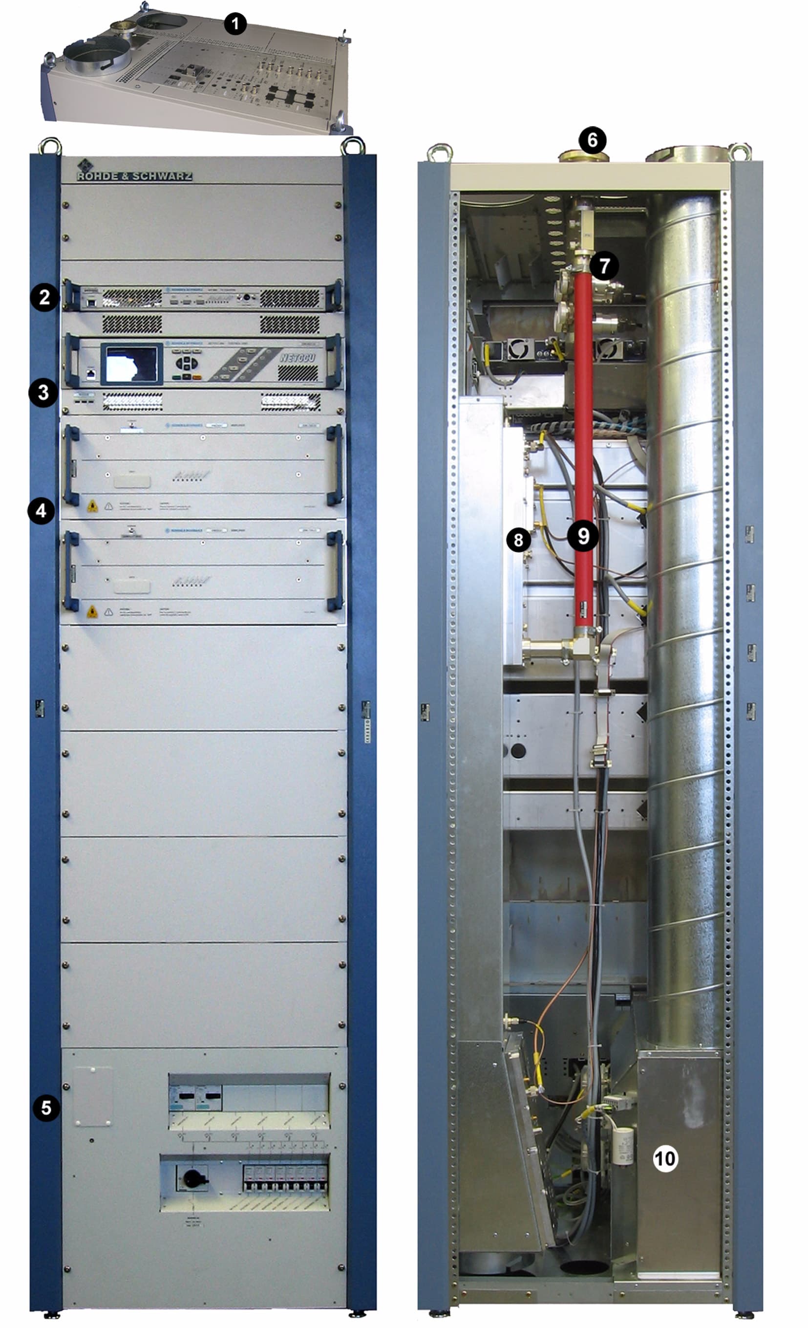
BQMNW8201E
Jan 17, 2008DIGITAL TELEVISION BROADCAST TRANSMITTER
Equipment Class
TBC - Licensed Broadcast Station Transmitter
BQMNH6050E
Aug 15, 2000Broadcast Television Transmitter
Equipment Class
TBC - Licensed Broadcast Station TransmitterBQM2280202026
Oct 07, 1998TBC - Licensed Broadcast Station Transmitter
Equipment Class
TBC - Licensed Broadcast Station TransmitterBQM22802027
Sep 25, 1998TBC - Licensed Broadcast Station Transmitter
Equipment Class
TBC - Licensed Broadcast Station TransmitterBQM22802331-3
Sep 25, 1998TBC - Licensed Broadcast Station Transmitter
Equipment Class
TBC - Licensed Broadcast Station Transmitter