BQMNW8201EDIGITAL TELEVISION BROADCAST TRANSMITTER
Acrodyne Industries, Inc.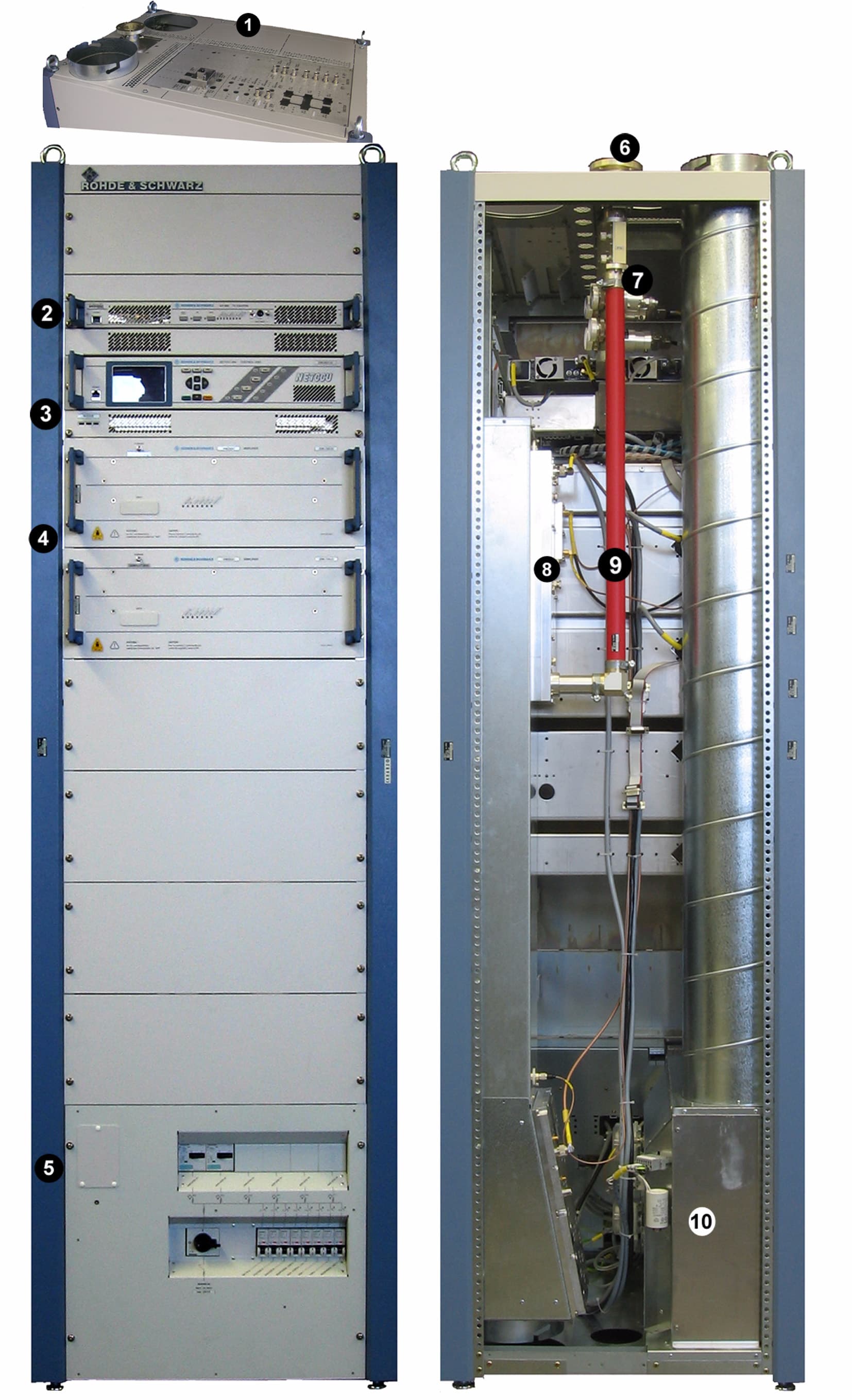
Click to zoom
Application Details
- Equipment Class
- TBC - Licensed Broadcast Station Transmitter
- Date of Grant
- Jan 17, 2008
- Application Purpose
- Original Equipment
- Date of Application
- Oct 25, 2007
- Equipment Note
- DIGITAL TELEVISION BROADCAST TRANSMITTER
- Frequency Range
- 174.00000000 - 216.00000000
- Company
- Acrodyne Industries, Inc.
- Country
- United States
Documents & Files
Document Text
Text extracted from the exhibit documents filed with the FCC. Open a document above to read the original.
Users Manual
Broadcasting Division 2099.9595.72 -01 - 0.1 - System Manual NW8202E/V DTV Transmitter Transmitter Series Nx8000 Only skilled personnel may perform the operations of the described instrument that are necessary for installing and putting it into operation as well as maintaining, trou- bleshooting and servicing it. Printed in Germany System Manual Transmitter Series Nx8000 Edition: Oktober 2007 Version:E 01.00 2099.9595.72 -01 - 0.2 - This document may be duplicated or otherwise used or its contents made known to third parties only with permission of the originator or other authorized persons. Infringements constitute an offence and are subject to claim for damages (UrhG, UWG, BGB). All rights reserved for patenting or utility model registration. ROHDE & SCHWARZ GmbH & Co.KG D-81671 München - Mühldorfstraße 15 Telefon: (089) 4129-0 ^ Int. +49894129-0 Telefax: (089) 4129-12164 Internet: www.rohde-schwarz.com Printed in Federal Republic of Germany ^ Subject to change ^ Data without tolerances: typical values 2090.6870.54- EU -D/E-2 Für Betrieb im Europäischen Wirtschaftsraum (EWR) und zivilem Einsatz. Hinweis gemäß dem Gesetz über "Funkanlagen und Telekommunikationsend- einrichtungen" (FTEG) und der Europäischen Richtlinie 1999/5/EG: Dieses Produkt darf innerhalb des EWR nicht uneingeschränkt betrieben werden, da der verwendete Frequenzbereich auf nicht harmonisierten Bändern erfolgt. Nationale Vorschriften / Genehmigungen sind zu beachten. Das Gerät ist 4 Wochen vor Inverkehrbringen bei der jeweils zuständigen nationalen Behörde für die Frequenzhoheit zu notifizieren. Informationen hierzu im Internet unter folgender Adresse: http://europa.eu.int/comm/enterprise/rtte/spectr.htm For operation in the European Economic Area (EEA) and civil use. Note pursuant to the German Radio and Telecommunications Terminal Equip- ment Directive (FTEG) and the European R&TTE Directive 1999/5/EC: Operation of this product within the EEA is subject to restrictions since the frequency bands used are not harmonised. National provisions / authorizations shall be com- plied with. The product shall be notified to the competent national frequency management authority four weeks before the product is put on the market. For more information refer to: http://europa.eu.int/comm/enterprise/rtte/spectr.htm Printed in Germany 2099.9595.72 - 0.3 - E-1 NW8202E/V CONTENTS SAFETY INSTRUCTIONS1 DESIGN AND CHARACTERISTICS2 INSTALLATION3 COMMISSIONING4 OPERATING5 MAINTENANCE6 TROUBLESHOOTING7 SERVICE8 ANNEX9 Broadcasting Division 2095.7346.32- 1.0 -E-1 CHAPTER 1 SAFETY INSTRUCTIONS Printed in Germany Chapter 1Safety Instructions 2098.1190.72- 1.01 -E-2 CONTENTS 1 About this Manual ............................................................................ 1 2 Safety Instructions for Transmitter Systems and Instruments ... 2 3 General Safety Instructions ............................................................ 3 4 Special Danger Warnings ............................................................... 4 4.1 Hazards due to AC Supply Voltage ...............................................................4 4.1.1 AC Power Supply .........................................................................................4 4.1.2 Replacing Fuses ...........................................................................................5 4.1.3 Emergency-Off Equipment ...........................................................................5 4.1.4 Opening the Transmitter ...............................................................................5 4.2 Hazards due to High-Energy Circuits ...........................................................6 4.3 RF Hazards ......................................................................................................6 4.3.1 Mandatory Training ......................................................................................6 4.3.2 RF Shielding .................................................................................................7 4.3.3 Rules for Operating the Transmitter .............................................................7 4.3.4 Rules for Working with an Open Transmitter ...............................................7 4.4 Fire Hazards ....................................................................................................8 Chapter 1Safety Instructions 2098.1190.72- 1.1 -E-2 1About this Manual This manual is part of the documentation for the NX8000 family of transmitters from Rohde & Schwarz. Each transmitter and each transmitter component is described in a separate manual. The individual manuals of the family of transmitters are modular in structure and complement each other. Structure Each transmitter component is described in a separate manual and can thus be used as an individual component (where practical). The transmitter manual is the main document for the entire set of documentation. It describes all steps that are necessary to install a trans- mitter, put it into operation, operate and maintain it. Where applicable, the transmitter man- ual refers to the individual manuals for the various components. The component manuals, in turn, also refer to the transmitter manual whenever the component is to be used as a transmitter module. Contents The manuals for the family of transmitters describe all steps required to install the transmit- ter or one of its components, put them into operation, operate and maintain them, trouble- shoot and service them. The Annex includes interface descriptions plus technical documents. For convenience, all manuals are structured identically. Sections that are not relevant to the manual at hand are also included but are left blank. Safety All skilled personnel working with a transmitter or its components must read all relevant manuals and comply with the safety measures that are detailed in the chapter about safety and in the applicable sections in the manual. The transmitter and the individual transmitter components …
Text truncated - open the document above for the full version.
Users Manual
Broadcasting Division 2095.7346.32- 2.0 -E-1 CHAPTER 2 DESIGN AND CHARACTERISTICS Printed in Germany Chapter 2Design and Characteristics 2099.9595.72 - 2.01 - E-1 CONTENTS 1 DESIGN AND FUNCTION ................................................................. 1 1.1 Power Distribution ..........................................................................................4 1.1.1 Main Switch (Power Supply Terminal) .........................................................4 1.1.2 Motor Protection Switch ...............................................................................5 1.1.3 Automatic Line Fuse .....................................................................................6 1.1.4 Power Distribution Board ..............................................................................6 1.1.5 Auxiliary Power Supply .................................................................................7 1.1.6 Optional Socket ............................................................................................8 1.1.7 Grounding Bolt .............................................................................................8 1.2 Transmitter Control Unit ................................................................................9 1.2.1 NETCCU ......................................................................................................9 1.2.2 Rack Controller ...........................................................................................10 1.3 Connection Panel .........................................................................................11 1.4 Exciter Unit ....................................................................................................12 1.4.1 Exciter ........................................................................................................13 1.4.2 Exciter Switch .............................................................................................13 1.5 Output Stage Unit .........................................................................................14 1.5.1 Splitter ........................................................................................................16 1.5.2 Amplifier .....................................................................................................17 1.5.3 Combiner ....................................................................................................18 1.5.4 Absorber .....................................................................................................19 1.6 Test Lightning Protection System ..............................................................20 1.6.1 Lightning Protection ....................................................................................20 1.6.2 Directional Coupler .....................................................................................21 1.6.3 Test Interface .............................................................................................22 1.7 Harmonics Filter ...........................................................................................22 1.8 RF Connector ................................................................................................23 1.9 Cooling system .............................................................................................24 1.9.1 Air Intake/Exhaust Duct ..............................................................................25 1.9.2 Fans ...........................................................................................................26 1.9.3 Starting Capacitor .......................................................................................27 1.9.4 Differential Pressure Gage .........................................................................28 1.9.5 Temperature Sensors .................................................................................29 Chapter 2Design and Characteristics 2099.9595.72 - 2.02 - E-1 1.10 Transformer ..................................................................................................30 2 SPECIFICATIONS ........................................................................... 31 2.1 Transmitter System in General ...................................................................31 2.2 Transmitter System - Specifically NW8202 .................................................31 Chapter 2Design and Characteristics 2099.9595.72 - 2.1 - E-2 1Design and Function The new, air-cooled Transmitter Family NW820x is designed for transmitting digital TV sig- nals in the IV and V frequency bands (UHF). The digital standards DVB-T, ATSC, DMB-T and MediaFLO can be transmitted. LDMOS transistor-based amplifiers ensure high output power while requiring only minimum space. For digital TV, output power of 325 W to 1.95 kW is available. Both the power class of the transmitter and it s type designation depend on the number of built-in amplifiers. This chapter describes the transmitter's design and the functions of its components. NameNumber of amplifiersPower NW8201 1 325 W NW8202 2 650 W NW8203 3 975 W NW8204 4 1.3 kW NW8205 5 1.625 kW NW8206 6 1.95 kW Chapter 2Design and Characteristics 2099.9595.72 - 2.2 - E-2 Fig. 1 Block diagram of DTV transmitters: In this example NW8204E/V Exciter S tandby Amplifier V M 8 35 0A1 = Lightning Protection Measurement Coupler Harmonics Filter RF Output max. 6 V M835 0A1 Input Interface DTV TS1 TS2 TS3 TS4 Ext 1PPS Coder I Q Linear and nonlinear Precorrection Upconverter Dig. IQ Dig. IF 120MHz Synthesizer Down- converter PLL Mainboard LO Mon. Ext. REF 10MHz Mon. RF N RF DTVRF Mon. TV Exciter SX800 A 3xTS 120MHz Control 1pps Input Interface DTV TS1 TS2 TS3 TS4 Ext 1PPS Coder I Q Linear and nonlinear Precorrection Upconverter Dig. IQ Dig. IF 120MHz Synthesizer Down- converter PLL Mainboard LO Mon. Ext. REF 10MHz Mon. RF N RF DTVRF Mon. TV Exciter SX800 B 3xTS 120MHz Control 1pps Option Chapter 2Design and Characteristics 2099.9595.72…
Text truncated - open the document above for the full version.
Users Manual
Chapter 2Design and Characteristics 2099.9595.72 - 2.9 - E-2 1.1.6Optional Socket Fig. 10Optional socket The optional socket is not connected with the transmitter network and must be supplied by means of a separate power lead. 1.1.7Grounding Bolt Fig. 11Grounding bolt The grounding bolt connects the rack with the station's main grounding terminal. NoteThe rack must be connected to the main grounding terminal in all cases. Chapter 2Design and Characteristics 2099.9595.72 - 2.10 - E-2 1.2Transmitter Control Unit Fig. 12Equipment of the transmitter control unit 1) NETCCU 2) Rack controller The transmitter control unit contains the following components: NETCCU ® Rack controller They monitor and control the transmitter to ensure that it functions properly. 1.2.1NETCCU Fig. 13NETCCU The NETCCU ® 800 transmitter control unit is responsible for both internal and external communication, including all control functions. The NETCCU ® 800 shows the current status of the transmitter system on a color display. NoteFor detailed information about the NETCCU ® , refer to the NETCCU ® manual. Chapter 2Design and Characteristics 2099.9595.72 - 2.11 - E-2 1.2.2Rack Controller Fig. 14Rack controller The rack controller is used to monitor, control and protect the transmitter rack. It handles the following functions: Keeps the transmitter running if the NETCCU ® fails Controls data exchange between the NETCCU ® and other components via CAN bus Monitors the outlet air temperature Acquires measured data about the intake and outlet air temperatures Transfers messages Accepts and outputs rack commands (e.g. transmitter ON -> amplifier ON, cooling sys- tem ON) Configures the test points (mode-dependent) Switches off the rack in the event of malfunction (e.g. fan failure) The following equipment and modules can be connected to the rack controller: NETCCU ® via CAN-Bus Exciter (1 or 2) External water pump (water-cooled transmitters) Amplifier stages (1 or 2) Power distribution Temperature sensors Power test points NoteThe rack controller cannot be operated directly. It is operated via the NETCCU ® .
Users Manual
Chapter 2Design and Characteristics 2099.9595.72 - 2.12 - E-2 1.3Connection Panel Fig. 15Connection panel The baseband signals as well as the monitoring and remote control connections are routed to the transmitter via the connection panel. Chapter 2Design and Characteristics 2099.9595.72 - 2.13 - E-2 The following table describes the connection options: 1.4Exciter Unit Fig. 16Exciter unit equipment 1) Exciter SX 800 2) Exciter switch (exciter standby only) The exciter unit contains the following components: ConnectorDescription CANBUS X101ACAN bus data connection for additional racks or output stage A CANBUS X101B CAN bus data connection for additional racks or output stage B CANBUS X101C CAN bus data connection for external pump in the case of high-power transmitters RS232 X232Serial data connection for external BITBUS interface ETHERNETRemote LAN connector or system LAN connector, e.g. for N+1 ANTENNA 1 INPUTAntenna connector for receiver module input 1 in the NETCCU ® (DTV only) ANTENNA 2 INPUTAntenna connector for receiver module input 2 in the NETCCU ® (DTV only) TS1 / TS2Transport stream inputs (digital TV) TS3 / TS4Additional connectors to TS1 and TS2 in the case of hierarchical cod- ing 10 MHz REF INPUTInput for 10 MHz reference for synchronizing the output signal 1PPS MONITORINGTest output 1PPS (1PPS = 1 pulse per second) 1PPS EXT INPUTInput for 1PPS signal, reference signal for DVB-T in SFN mode T TS1/2 MONITORINGMonitor output for selected TS signal of inputs 1 and 2 TS3/4 MONITORINGMonitor output for selected TS signal of inputs 3 and 4 Chapter 2Design and Characteristics 2099.9595.72 - 2.14 - E-2 Exciter Exciter switch (in case of exciter standby) 1.4.1Exciter Fig. 17Exciter The Exciter SX 800 performs all signal processing from the transport signal up to a stan- dard-compliant RF output signal. NoteFor detailed information about the exciter, refer to the exciter manual. 1.4.2Exciter Switch Fig. 18Exciter switch NoteThe exciter switch is included in transmitters with the exciter standby option (two exciters); it is located behind the two exciters. The exciter switch switches to the standby exciter in the following cases: When the main exciter malfunctions When manual switchover is performed via the NETCCU ® The exciter switch is controlled by the NETCCU ® .
Users Manual
Chapter 2Design and Characteristics 2099.9595.72 - 2.15 - E-2 1.5Output Stage Unit Fig. 19Output stage unit equipment 1) Splitter 2) Amplifiers 3) Combiner 4) Absorber The output stage unit contains the following components: Splitter Amplifiers Combiner Absorber The following figure shows the entire RF branch from X.E. (splitter input) up to X.A. (com- biner output). Chapter 2Design and Characteristics 2099.9595.72 - 2.16 - E-2 Fig. 20 Block diagram of the output stage unit - in this example NW8204
Users Manual
Chapter 2Design and Characteristics 2099.9595.72 - 2.17 - E-2 1.5.1Splitter Fig. 21Combiner (1) with splitter (2) The splitter distributes the output signal of the exciter to the individual amplifiers. In addition, an integrated attenuator pad that is dependent on the number of outputs ensures that the RF signal is output at the right power level. The broadband splitter can be used in the frequency range 170 MHz to 254 MHz.
Users Manual
Chapter 2Design and Characteristics 2099.9595.72 - 2.18 - E-2 1.5.2Amplifier Fig. 22Amplifier The air-cooled, broadband VM8350A1 amplifier operates in the range from 170 MHz to 254 MHz (VHF band III). It can be used both for analog and digital signals without re- quiring any adjustments. The output power of an amplifier is 325 W in the case of digital TV. The amplifiers amplify the exciter signals distributed by the splitter and forward them to the combiner. The amplifiers in a transmitter rack are controlled via the rack controller. Mea- sured values and status information are recorded by the rack controller via CAN bus and forwarded to the NETCCU ® transmitter control unit. The number of exciters in the transmit- ter depends on the transmit power. NoteFor detailed information about the amplifier, refer to the amplifier manual. Chapter 2Design and Characteristics 2099.9595.72 - 2.19 - E-2 1.5.3Combiner Fig. 23Combiner (1) with splitter (2) The RF power output by the amplifiers is merged via the combiner. The combiner consists of a cascade of 3 dB couplers housed in a single unit. Chapter 2Design and Characteristics 2099.9595.72 - 2.20 - E-2 1.5.4Absorber Fig. 24Absorber The absorber functions as the absorber resistor for the combiner. If combiner operation is not symmetrical (e.g. one or more amplifiers are disconnected or removed), the portion of the RF power that cannot be coupled in is expelled as additional thermal energy via the transmitter's exhaust system.
Users Manual
Chapter 2Design and Characteristics 2099.9595.72 - 2.21 - E-2 1.6Test Lightning Protection System Fig. 25Equipment in the test lightning protection system 1) Lightning protection 2) Directional coupler N 3) Directional coupler SMA 4) Directional coupler and rectifier unit The test lightning protection system (lightning protection combined with test points) is locat- ed at the output of the harmonics filter and contains the following components: Lightning protection Directional coupler N Directional coupler SMA (option ADE only) Directional coupler and rectifier unit 1.6.1Lightning Protection The lightning protection protects the rack from possible damage due to lightning bolts. Chapter 2Design and Characteristics 2099.9595.72 - 2.22 - E-2 1.6.2Directional Coupler Fig. 26Directional coupler The forward and reflected power are detected at the transmitter output by means of the fre- quency-compensated directional couplers P14A (forward) and P14B (reflected). The fre- quency-compensated directional couplers send a power-proportional DC voltage to the NETCCU ® transmitter control unit via the integrated rectifier circuit. The DC voltages for the forward and reflected values are displayed in the NETCCU ® and also used as an S-mea- surement for VSWR monitoring (reflection antenna). Directional coupler P14C is an unassigned test point that can be used either as a forward or reflected power test point. The P14D rectifier is used in the digital TV transmitter in connection with option ADE only. NoteThe transmitter is switched off because of reflection if the reflected value exceeds 2% of the forward value after being checked three times. Chapter 2Design and Characteristics 2099.9595.72 - 2.23 - E-2 1.6.3Test Interface Fig. 27Te st i nt e r f a c e External power measurement equipment can be connected at the unused test interface. 1.7Harmonics Filter Fig. 28Harmonics filter Chapter 2Design and Characteristics 2099.9595.72 - 2.24 - E-2 Harmonics filter FM 825 suppresses harmonics. It is set up as a Chebyschev filter of the 11th order using coaxial design for the 13-30 line system. In the signal path, the harmonics filter is located directly after the combiner. NoteThe harmonics filter is lacquered in order to reduce the surface temperature, but high tem- peratures are nevertheless to be expected. 1.8RF Connector Fig. 29RF connector The RF connector (1 5 / 8 “ EIA flange) is located on the transmitter roof (or under it if pre- ferred).
Users Manual
Chapter 2Design and Characteristics 2099.9595.72 - 2.25 - E-2 1.9Cooling system Fig. 30Cooling system 1) Air intake duct 2) Fan 3) Starting capacitor 4) Differential pressure gage 5) Temperature sensor The cooling system with its two integrated fans (active standby) prevents the transmitter from overheating and contains the following components: Air intake/exhaust duct Fans (2) Starting capacitor (2) Differential pressure gages (2) Temperature sensors (2) Chapter 2Design and Characteristics 2099.9595.72 - 2.26 - E-2 1.9.1Air Intake/Exhaust Duct Fig. 31Air intake duct (1) and exhaust duct (2) The air from the intake duct is drawn in by the fans and forwarded to the distribution shaft. The distribution shaft provides enough air to each amplifier to cool it. The heated air is rout- ed to an air collecting shaft on the opposite site of the amplifier and expelled via the exhaust duct. NoteThe intake/exhaust outputs are located either on the top or bottom of the rack, depending on your order specifications. If the intake is at the bottom, there is no intake duct. The connecting flange is located di- rectly beneath the output box. In addition, the absorber unit is situated at the bottom and it feeds into the exhaust connec- tion. Chapter 2Design and Characteristics 2099.9595.72 - 2.27 - E-2 1.9.2Fans Fig. 32Fans A standard transmitter rack contains two fans, which adequately cool the transmitter with air. If one of the fans is defective, a warning is sent to the controller but the transmitter con- tinues to operate. If both fans fail, the rack controller switches off the affected rack. The transmitter indicates a cooling malfunction. Chapter 2Design and Characteristics 2099.9595.72 - 2.28 - E-2 1.9.3Starting Capacitor Fig. 33Starting capacitor Each motor is equipped with an external starting capacitor. Chapter 2Design and Characteristics 2099.9595.72 - 2.29 - E-2 1.9.4Differential Pressure Gage Fig. 34Differential pressure gage The differential pressure gages (diaphragm switches) measure the differential pressure of each fan between the fan flange (output) and the environment. Thus, fan malfunctions can be selectively sent to the transmitter control unit. Chapter 2Design and Characteristics 2099.9595.72 - 2.30 - E-2 1.9.5Temperature Sensors Fig. 35Temperature sensors The temperature sensors measure the absolute intake and exhaust temperature in °C for display on the NETCCU ® and for monitoring in the rack controller. NoteIf the exhaust temperature is higher than 65 °C, the rack controller switches the rack off due to the danger of overheating. Chapter 2Design and Characteristics 2099.9595.72 - 2.31 - E-2 1.10Transformer Fig. 36Transformer The transformer converts the voltage in the event of local voltage differences, e.g. in the United States or Canada (AC power supply 115 V/200 V). NoteFor detailed information about the transformer, refer to the transformer manual.
Users Manual
Chapter 2Design and Characteristics 2099.9595.72 - 2.32 - E-2 2Specifications 2.1Transmitter System in General Frequency range ........................................ 170 MHz to 254 MHz Voltage supply ............................................ 3 x 400 V AC ± 15% 47 Hz to 63 Hz three-phase Maximum installation altitude ..................... 2000 m above sea level (over 2000 m on request) Operating temperature range ..................... +1° C to +45° C Max. permissible humidity .......................... 95%, noncondensing Dimensions (W x H x D) ............................. 600 mm x 2000 mm x 800 mm RF Connector ............................................. 1 5 / 8 EIA Synchronization Reference frequency .................................. 10 MHz, 0.1 V to 5 Vpp or TTL, BNC Reference puls ........................................... 1 Hz, TTL, BNC Operation Local Color display and keys .......................... Front control via graphical user interface (GUI) RJ-45 ..................................................... Operation via PC using standard web browser Remote RJ45 ...................................................... IEC864-2 via Ethernet (standard) RJ45 ...................................................... Network management interface (web server and/or SNMP agent, optional) Parallel I/O interface .............................. Floating contacts for messages and com- mands (optional) BITBUS ................................................. Bus interface in accordance with IEC 864-2 (optional) 2.2 Transmitter System - Specifically NW8202 Number of amplifiers .................................. 2 P out ............................................................ 650 W Air throughput............................................. At least 8.5 m 3 /min Power consumption.................................... 3.2 kW ± 10% Backup fuse................................................ 3 x 16 A Line cross-section....................................... 2.5 mm 2 Chapter 2Design and Characteristics 2099.9595.72 - 2.33 - E-2 Total weight (approx.) ................................. 270 kg Inputs (DVB-T/H) ........................................ 4 x ASI Coding and modulation............................... According to EN 300744, EN 302304 (optional) Modulation .................................................. QPSK, 16QAM or 64QAM Guard interval ............................................. 1/4, 1/8, 1/16 or 1/32 usefull symbol period IFFT mode .................................................. 2 k and 8 k, 4 k (optional) Innere code rate ......................................... 1/2, 2/3, 3/4, 5/6 or 7/8 Useful symbol period .................................. 224 μs (2 k) or 896 μs (8 k), 448 μs (4 k, optional) Broadcasting Division 2095.7346.32- 3.0 -E-1 CHAPTER 3 INSTALLATION Printed in Germany Chapter 3Installation 2099.9595.72 - 3.01 - E-2 CONTENTS 1 Equipment Supplied ........................................................................ 1 1.1 Integrated Transmitter Components ............................................................1 1.2 Transmitter Components Supplied Separately ...........................................2 2 Overview ........................................................................................... 3 3 Transmitter Setup ............................................................................ 4 3.1 Transmitter Rack Setup .................................................................................4 3.2 Transmitter Rack Alignment ..........................................................................4 3.3 Removal of Front Panels/Rear Panel ............................................................4 3.4 Unpacking of Components ............................................................................5 4 Transformer ...................................................................................... 6 5 Ventilation System ........................................................................... 7 5.1 Connection of Intake/Exhaust Ducts ............................................................7 5.2 Connection of External Backup Fan ...........................................................10 5.3 Check of Ventilation Covers ........................................................................10 5.4 Checking of Differential Pressure Gage .....................................................11 6 AC Power Supply ........................................................................... 12 6.1 Connection of Transmitter Ground .............................................................13 6.2 Connection of AC Power Cable ...................................................................13 6.3 Connection of External Equipment .............................................................15 7 Amplifiers ....................................................................................... 16 7.1 Installing the Amplifier .................................................................................16 8 Connection of Antenna/Dummy Antenna to RF Connector ...... 17 8.1 Connection of Antenna ................................................................................17 8.2 Connection of Dummy Antenna ..................................................................18 9 Connection Panel .......................................................................... 19 Chapter 3Installation 2099.9595.72 - 3.1 - E-2 1Equipment Supplied 1.1Integrated Transmitter Components When you receive the Transmitter NV820x, the following units and modules are already in- stalled in the rack if they form part of your order: NoteUse the tables below to check that all the relevant components have been supplied. QtyDesig…
Text truncated - open the document above for the full version.
Contact Information
Applicant
Mark H. Bricker(Sr. Systems Engineer)
Technical Contact
ACRODYNE INDUSTRIES, INC.MARK H. BRICKER
[email protected]610-917-1300
200 SHELL LANE · PHOENIXVILLE, Pennsylvania · United States
Technical Specifications
| # | Rule Parts | Frequency Range | Power Output | Emission | Tolerance |
|---|---|---|---|---|---|
| 1 | 74 | 174 MHz - 216 MHz | 500 W | 5M38C7W | 1000.0000000000 Hz |
Other Applications from Acrodyne Industries, Inc.
BQMNH6050E
Aug 15, 2000Broadcast Television Transmitter
Equipment Class
TBC - Licensed Broadcast Station Transmitter
BQM22802332
Sep 23, 1999Broadcast Television Transmitter
Equipment Class
TBC - Licensed Broadcast Station TransmitterBQM2280202026
Oct 07, 1998TBC - Licensed Broadcast Station Transmitter
Equipment Class
TBC - Licensed Broadcast Station TransmitterBQM22802027
Sep 25, 1998TBC - Licensed Broadcast Station Transmitter
Equipment Class
TBC - Licensed Broadcast Station TransmitterBQM22802331-3
Sep 25, 1998TBC - Licensed Broadcast Station Transmitter
Equipment Class
TBC - Licensed Broadcast Station Transmitter