BRWDAMTX102.4 GHz Transceiver
Horizon Hobby, LLC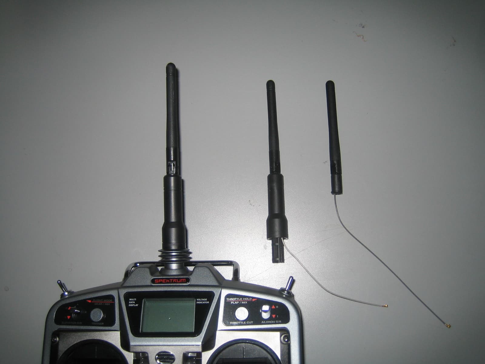
Click to zoom
Application Details
- Equipment Class
- DTS - Digital Transmission System
- Date of Grant
- Jan 03, 2006
- Application Purpose
- Original Equipment
- Date of Application
- Jan 03, 2006
- Equipment Note
- 2.4 GHz Transceiver
- Frequency Range
- 2402.00000000 - 2478.00000000
- Company
- Horizon Hobby, LLC
- Country
- United States
Documents & Files
Document Text
Text extracted from the exhibit documents filed with the FCC. Open a document above to read the original.
Users Manual
X1TXN 2.4GHz DSSS Module User Manual. Horizon Hobby Inc., 1657 Country Club Dr., Milpitas CA 95035 USA 408 945 9800 1. Features • 2.4GHz Direct Sequence Spread Spectrum (DSSS) radio transceiver module. • Operates in the unlicensed worldwide ISM band (2.4 GHz to 2.483.5GHz) band • Fully integrated power regulation with a wide input unregulated operating range 2.4 to 3.6V. • Fully integrated local oscillator and 12MHz 20ppm reference crystal • 200mA operating current • Transmit power - 200mW EIRP • Receive sensitivity up to -95dBm • DSSS data rates up to 250kbps • 1 mile operating range • Full packet assembling and disassembling • Auto transaction sequencer • Fully buffered digital interface with high voltage tolerant inputs 2. Pin description Pin Number Name Description 1 GND Module Ground 2 VDD Module power input 3 IRQ Interrupt Request 4 RST Reset, active High 5 MOSI Master out, slave In data 6 nSS Slave Select, Active Low 7 SCLK SPI data clock 8 MISO Master in, slave out data 9 GND Module Ground 10 XOUT Clock output from module 11 TXRX Switch antenna to transmit direction 12 RXTX Switch antenna to receive direction 3. Specifications Parameter Value Units Storage Temp -65 to 105 Degrees Celsius VDD 2.4 to 3.6 Volts Receive Sensitivity -95 dBm Transmit power (conducted) 21 dBm MAX Transmit power (radiated) 23 dBm MAX Idle current 1 mA Receive current 22 mA Transmit current 200 mA 4. Block Diagram 5. Module User Requirements 5.1 This module must be integrated into a device where the user cannot access the antenna connector and should not be able to remove/install the module. 5.2 Only a 2dBi antenna can be used with this module. The antenna must meet and not exceed the gain and pattern of the supplied Inpaq DAM00BM11500209 folded dipole antenna. 5.3 This module must not be co-located or operated in conjunction with any other antenna or transmitter. 5.4 The device must contain the following permanent labeling on the exterior of the device as follows: Contains FCC ID: BRWDAMTX10 5.5 The user manual of the device must contain the following paragraph: This device complies with part 15 of the FCC rules. Operation is subject to the following two conditions: (1) This device may not cause harmful interference, and (2) this device must accept any interference received, including interference that may cause undesired operation. Caution: Changes or modifications not expressly approved by the party responsible for compliance could void the user’s authority to operate the equipment. This product contains a radio transmitter with wireless technology which has been tested and found to be compliant with the applicable regulations governing a radio transmitter in the 2.400 GHz to 2.4835 GHz frequency range. The following countries associated regulatory agencies recognizing the noted certifications for this product as authorized for sale and use are: USA Canada Belgium Denmark France Finland Germany Italy Netherlands Spain Sweden UK 5.6 This module meets the requirements for a mobile device that may be used at separation distances of more than 20cm from the human body. To meet the rf exposure requirements of the FCC this device shall not be co-located with another transmitting device.
Cover Letter(s)
American TCB December 21, 2005 RE: FCC ID: BRWDAMTX10 Attention: Tim Johnson Please find our responses to your comments on this Application below: 1) Please verify labeling information. Internal Photographs provided appears to suggest a different FCC ID. Internal photographs have been updated with the correct label. Original photographs showed the label for a lower-power version of this device 2) Agent letter was not provided – the exhibit labeled as such was actually a confidentiality letter. Please provide. Agent authorization has been uploaded. 3) Please provide a bottom view of the board with the label removed. Internal photographs have been updated with the correct label (moved to the front of the device and on top of the shield), a photo of the bottom of the board without the original label and photos of the top with and without shields have been uploaded as a new exhibit. (See also (1) above). 4) The device appears to be tested within a portable device. This type of device is commonly held against the stomach during use and 20 cm as a mobile device does not appear to always be possible. Note this type of transmitter commonly have a neck strap as well. Please review/explain in more detail the intended types of installations. The device provided was used for convenience to provide power/signaling to the EUT, but the host system will not be used with this device. The host systems that will use this device will be designed to ensure that the antenna and its feed point will be positioned on the device to provide a 20cm separation from persons. Further the host device will be designed to ensure that the normal location of hands on the controller and the location of the controls will also be more than 20cm from the antenna. To relieve some of these issues please change the application to one for limited modular approval. The limitations should restrict the module’s use to Horizon Hobby’s end products. 5) Photographs regarding what antenna was tested (i.e. to be approved) was not provided. Please provide. The antenna specification sheet and a photograph of the antenna have been uploaded. Page 2 of 3 6) Please comment on the high spur seen at 30 MHz on page 41. The spur is, in fact, the artifact of “0Hz”, this occurs on the first plot plots but not on all. This is noted in the text immediately above the first plot. As this artifact was 20dB below the fundamental the engineer did not re-take the measurement. 7) Users manual page 2 mentions a 200 mW EIRP rating, while page 3 mentions 20 dBm Radiated maximum. The report suggests 128 mW maximum. Please review/correct as necessary. The guide has been updated to reflect the correct values of 21dBm for conducted power and 23dBm for eirp. 8) Instructions to the integrator appear to suggest use of the FCC Logo (DoC Authorization). However it is uncertain how this can be instructed to the integrator since it is uncertain how the device will be used (applicant doesn’t control use by integrator, and integrator should only label DoC when applicable). There is no justification for a DoC procedure for this device. The suggested use of the FCC logo has been removed from the user instructions. 9) The users manual should also caution the integrator that this device may not be co-located with another transmitter per FCC RF exposure requirements. The wording “To meet the rf exposure requirements of the FCC this device shall not be co-located with another transmitting device.” has been added to the user manual. 10) Please explain the intent of this module as these are typically not allowed to be installed by the end user and also not clear what types of devices this is intended for. It is uncertain if these devices can meet appropriate RF exposure requirements if their intent is for a portable controller. The modules will be used in purpose-built controllers that are designed to operate in the 2.4 GHz band (current units use alternative frequency bands for model control). There is no intent to provide the end user with the module, in fact the end user would not have access to the module as it would be installed inside the controller. Limited modular approval is requested to limit use of the module to the Horizon Hobby. See also item (4) above for rf exposure concerns. 11) FYI....It is recommended that the users manual provide information that the end user is not to be given information on how to install or remove this device. As per your recommendation this instruction is included in section 5.1 of the user’s guide. Page 3 of 3 12) FYI....Generally the FCC strongly prefers for the FCC ID to be visible to the user upon purchase and after installation (when possible). Modular approvals are somewhat unique in the respect that they do get integrated and it is hard to meet this requirement per se. However generally we see that these types of devices would place the labels on the shield of the device. By placing on the bottom side of the board, anyone opening the device (for any reason, including compliance issues) may not have access to the label, especially if the board is soldered in by the integrator instead of placed on a removable mount. We highly suggest that labeling be done on the shield on the other side of the board instead of underneath. As per your recommendation the label is now on the shield. 13) FYI....Proposed Grant Notes: Power Output listed is Conducted. Limited Modular Approval (LMA) restricted to installation in devices manufactured by that applicant. Information must not be provided to the end user regarding how to install or remove this RF module in the user’s manual of the end product which will integrate this module. The antenna used for this transmitter must be installed to provide a separation distance of at least 20 cm from all persons and must not be co-located or operating in conjunction with any other antenna or transmitter. End-users must be provided with transmitter operating conditions for satisfying RF exposure compliance. Noted an…
Text truncated - open the document above for the full version.
Cover Letter(s)
January 3, 2006 American TCB RE: Horizon Hobby FCC ID: BRWDAMTX10 1) Please verify labeling information. The revised Internal Photographs provided still appears to suggest a different FCC ID. Please be sure this exhibit also shows a bottom view of the board with any labels removed. Please see revised internal photo. Regards, Jennifer Sanchez
Cover Letter(s)
Paul Beard Horizon Hobby Inc. 1657 Country Club Dr., Milpitas CA 95035 USA American TCB 6731 Whittier Ave Suite C110 McLean, Va. 22101 November 27th 2005 Dear Examiner: I am writing to avoid the possibility of an inadvertent disclosure of proprietary information. The accompanying Form 731 is being filed with the commission on our behalf by Elliott Laboratories, Inc., a consulting and testing laboratory. Included as exhibits with the enclosed application are block diagrams, schematics, and a detailed description of the theory of operation of the device. It is our intention to provide the commission with a full disclosure of our product so that its merits can be evaluated. Indeed, we are pleased to provide any further information that the commission might wish to see. It is not our intention, however, to make our proprietary process a matter of public record. In view of the fact that the block diagrams, schematics, and associated theory of operation disclose the mechanism of our process, we ask that these portions (block diagrams, schematics, and theory of operation) of our application be withheld from public inspection as provided under FCC section 0.459. These documents contain details of the proprietary operation of product. These details are not readily discernible - even to technically sophisticated individuals - from our hardware and constitute trade secrets. In addition, we request temporary non-disclosure for the user manual and all photographs. We request therefore that these documents and this letter be segregated from the body of our evaluation report and withheld from public inspection. Thank you for your attention. Please let the undersigned know if the Commission disagrees with our position or requires further justification. Sincerely, Paul Beard Inventor, Lead Engineer - Spektrum
Cover Letter(s)
American TCB 6731 Whittier Ave Suite C110 McLean, Va. 22101 Novemver 17th 2005 Gentlemen: This is your letter of authorization to accept our appointment of Elliott Laboratories, Inc. as Agent for Horizon Hobby Inc., 1657 Country Club Dr., Milpitas CA 95035, to sign applications before the Commission and to make representations to you on our behalf. Elliott Laboratories is to receive and exchange data between our company and the Commission. This authorization is made pursuant to Section 2.911(c) of the FCC Rules and expires on 27 th November 2006. I hereby certify on behalf of Horizon Hobby Inc., 1657 Country Club Dr., Milpitas CA 95035 ("Applicant") that neither Applicant nor any party to the application (officers, directors, and 5% shareholders) is subject to a denial of Federal benefits that includes FCC benefits pursuant to section 5301 of the Anti-Drug Abuse Act of 1988. 21 U.S.C. 853a. Sincerely, Paul Beard Inventor, Lead Engineer - Spektrum
Cover Letter(s)
EXHIBIT 10: Modular Approval Requirements Modular Approval is being requested for this device. There are eight requirements that the device must meet for full modular approval. The following paragraphs detail these requirements and the manner in which the device meets them. The module meets all of the technical specifications applicable to the frequency band of operation. The module has its own RF shielding. The top (component side) is fully enclosed by a tin plated shield which is soldered to the rf ground plane continuously on all 4 sides. The bottom (solder side) is a fully poured copper gound layer. No traces are on this layer. There are vias between the ground layer and shield at least every 0.020” All modulation and data input(s) are buffered. U1 contains isolators for each digital interface pin. The isolators are separately powered and are tolerant of being drive above the VDD of the device. The clock domain of this circuit is also independent. RESET is protected by a capacitor (C2) so that the device always powers into an idle state. The module has its own power supply regulation and local reference oscillator. The module contains its own power supply regulation and the rf reference oscillator is contained within the module. Power supply regulation is provided via six internal, separately decoupled LDOs inside U1. The module does not need to be powered by a regulated power source. The voltage range is 2.7 to 3.6Vdc. U1 also contains a complete VCO driven by an internal reference oscillator. The reference oscillator uses X1, a 12MHz reference crystal completely contain on the module. The modular transmitter must comply with the antenna requirements of Section 15.203 and 15.204(c). The certification submission contains a detailed description of the configuration of all antennas that will be used with the module. The module connects to its antenna via a micro-coax connector). This connector must be internally connected to the antenna without the possibility of user access. The antenna is a 2dBi folded dipole. Inpaq Antenna part# DAMA00BM11500209 was provided for testing. The antenna connector is not user accessible. Only folded dipole antennas with 2dBi gain or less can be used with this module. For Industry Canada, the module meets certification labeling requirements. Host devices that contain separately certified modules do not need to be re-certified, provided that they meet the following conditions: • The host device, as a stand alone unit without any separately certified modules, complies with all applicable Radio Standards Specifications. • The host device and all the separately certified modules it contains jointly meet the safety requirements of RSS-102, if applicable. • The host device complies with the certification labeling requirements of each of the modules it contains. The module is appropriately labeled with a permanently adhered white label on the solder side of the module. For the FCC, the modular transmitter must be tested in a stand-alone configuration, i.e., the module must not be inside another device during testing. This is intended to demonstrate that the module is capable of complying with Part 15 emission limits regardless of the device into which it is eventually installed. Unless the transmitter module will be battery powered, it must comply with the AC line conducted requirements found in Section 15.207. Test data contained in this application is for the device tested as a stand- alone battery powered device. Radiated spurious emissions data demonstrating compliance with the requirements of Part 15 of the FCC rules for intentional radiators has been provided. No AC conducted tests were performed as this module will only be used in battery operated devices. The module was mounted on the back of a plastic device (with no metal) with the antenna mounted in a typical orientation to best represent the arrangement of the module in a typical device. For the FCC, the modular transmitter must be labeled with its own FCC ID number, and, if the FCC ID is not visible when the module is installed inside another device, then the outside of the device into which the module is installed must also display a label referring to the enclosed module. This exterior label can use wording such as the following: “Contains Transmitter Module FCC ID: XYZMODEL1” or “Contains FCC ID: XYZMODEL1.” The module is appropriately labeled. The label is mounted on the solder side of the module. Information to the integrator of this system regarding the labeling requirements for the host system are contained in the instructions provided with the module (X1TXN User guide). The modular transmitter must comply with any applicable RF exposure The module meets the requirements for a mobile device that may be used at separation distances of more than 20cm from the human body. Refer to the MPE calculation.
ID Label/Location Info
J 1 Location of the FCC label FCC ID: BRWDAMTX10 X1TXN Module Horizon Hobby Inc., 1657 Country Club Dr., Milpitas CA 95035 USA 408 945 9800 X1TXN Label Drawing FCC ID: BRWDAMTX10 IC: 6157A-BRWDAMT 0.450" 0.725" Attached by permenant adhesive X1TXN Module Horizon Hobby Inc Model X1TXN X 1 T X N A Sheild PDF created with pdfFactory trial version www.pdffactory.com
Operational Description
UNLESS OTHER SPECIFIED TOLERANCES ON X 3 X.X 0.5 X.XX 0.05 ANGLES HOLEDIA INPAQ TECHNOLOGY CO., LTD. SCALE UNITmm DRAWN BY CHECKED BY: DESIGNED BY APPROVED BY THIS DRAWINGS AND SPECIFICATIONS ARE THE PROPERTY OF INPAQ TECHNOLOGY CO.,LTD.AND SHALL NOT BE REPRODUCED OR USED AS THE BASIS FOR THE MANUFACTURE OR SALE OF APPARATUS OR DEVICES WITHOUT PERMISSION DOCUMENT PAGE REV. TITLE2.4GHz A0 Type Antenna for DAMA0BR11500200 NO. 001510101041 A0 PAGE 1 OF 5 2.4GHz A0 Type Antenna for DAMA0BR11500200 1. Explanation of Part Number (1) Product type : DAM (2) Appearance Series : A0 (3) Frequency : B (4) Coaxial Cable Specification : R1 (5)Coaxial Cable Length : 150 (6)Connector Types :02 (7) Suffix for special requirements : 00 2. Electrical properties: Item Property Frequency Range 2.4~2.4835 GHz Impedance 50 Ω (Typ.) VSWR (see Fig 1) 2.0 max. Return loss (see Fig 2) -10 dB max. Gain 2.0 dBi (Typ.) Polarization Vertical Radiation pattern Near omni-directional in the horizontal plane Admitted power 1 W Electrical wave 1/2 dipole 50A1 R B1 00AMD (3)(1)(2)(4)(5)(6) 00 (7) 2 UNLESS OTHER SPECIFIED TOLERANCES ON X 3 X.X 0.5 X.XX 0.05 ANGLES HOLEDIA INPAQ TECHNOLOGY CO., LTD. SCALE UNITmm DRAWN BY CHECKED BY: DESIGNED BY APPROVED BY THIS DRAWINGS AND SPECIFICATIONS ARE THE PROPERTY OF INPAQ TECHNOLOGY CO.,LTD.AND SHALL NOT BE REPRODUCED OR USED AS THE BASIS FOR THE MANUFACTURE OR SALE OF APPARATUS OR DEVICES WITHOUT PERMISSION DOCUMENT PAGE REV. TITLE2.4GHz A0 Type Antenna for DAMA0BR11500200 NO. 001510101041 A0 PAGE 2 OF 5 Figure 1. VSWR Figure 2. Return Loss UNLESS OTHER SPECIFIED TOLERANCES ON X 3 X.X 0.5 X.XX 0.05 ANGLES HOLEDIA INPAQ TECHNOLOGY CO., LTD. SCALE UNITmm DRAWN BY CHECKED BY: DESIGNED BY APPROVED BY THIS DRAWINGS AND SPECIFICATIONS ARE THE PROPERTY OF INPAQ TECHNOLOGY CO.,LTD.AND SHALL NOT BE REPRODUCED OR USED AS THE BASIS FOR THE MANUFACTURE OR SALE OF APPARATUS OR DEVICES WITHOUT PERMISSION DOCUMENT PAGE REV. TITLE2.4GHz A0 Type Antenna for DAMA0BR11500200 NO. 001510101041 A0 PAGE 3 OF 5 Figure 3. Gain The Gain pattern was measuring in INPAQ’s FAR-field chamber . DUT will be placed on the table of rotator , a standard horn antenna and Vector Network Analyzer was using to collected data. ( Please contact to INPAQ for more detail ) z Measuring factors definition DUT Standard ANT. X (0 ) Y (90 ) Z 270 180 Chamber UNLESS OTHER SPECIFIED TOLERANCES ON X 3 X.X 0.5 X.XX 0.05 ANGLES HOLEDIA INPAQ TECHNOLOGY CO., LTD. SCALE UNITmm DRAWN BY CHECKED BY: DESIGNED BY APPROVED BY THIS DRAWINGS AND SPECIFICATIONS ARE THE PROPERTY OF INPAQ TECHNOLOGY CO.,LTD.AND SHALL NOT BE REPRODUCED OR USED AS THE BASIS FOR THE MANUFACTURE OR SALE OF APPARATUS OR DEVICES WITHOUT PERMISSION DOCUMENT PAGE REV. TITLE2.4GHz A0 Type Antenna for DAMA0BR11500200 NO. 001510101041 A0 PAGE 4 OF 5 3. Mechanical properties: Item Property Color Black ( Typ.) Coaxial-Cable Mini Coaxial 1.13 Plastic Cover TPU or TPE Antenna Base PC Fixed pin BSBM ( surface treatment ) Connector Mini Coaxial Connector Operating Temperature : -20~+65 Storage Temperature : -40~+80 4. Environmental Characteristics: No Item Test Condition Specification 4-1 High Temperature/Humidity Operating test 1.Temperature+60±2. 2.Humidity90~95%RH 3.Time24hrs 4-2 Low Temperature/Humidity Operating test 1.Temperature-20±2. 2.Humidity0%RH 3.Time24hrs 4-3 High Temperature/Humidity Storage 1.Temperature+80±2. 2.Humidity90~95%RH 3.Time88hrs 4-4 Low Temperature/Humidity Storage 1.Temperature-40±2. 2.Humidity0%RH 3.Time28hr 4-5 Temperature Cycle Operating Test 1.Temperature-40~+75 2.Duration z 88 Hours, z 45min/dwelling@ -40, z 10per min./transition from –40 to 75, z 45min/dwelling@75, 4-6 Temperature Shock Test 1.Temperature-40±~+85. 2.Time30 minutes/dwelling, 5 minutes/ transition, 24 cycles 1. Normal functional test must be satisfied after the test. 2. No material deformation is allowed. UNLESS OTHER SPECIFIED TOLERANCES ON X 3 X.X 0.5 X.XX 0.05 ANGLES HOLEDIA INPAQ TECHNOLOGY CO., LTD. SCALE UNITmm DRAWN BY CHECKED BY: DESIGNED BY APPROVED BY THIS DRAWINGS AND SPECIFICATIONS ARE THE PROPERTY OF INPAQ TECHNOLOGY CO.,LTD.AND SHALL NOT BE REPRODUCED OR USED AS THE BASIS FOR THE MANUFACTURE OR SALE OF APPARATUS OR DEVICES WITHOUT PERMISSION DOCUMENT PAGE REV. TITLE2.4GHz A0 Type Antenna for DAMA0BR11500200 NO. 001510101041 A0 PAGE 5 OF 5 4. Physical Dimension : 67.0±0.2 150±3mm 16.9±0.2 19.5±0.2 RG-178 Base2 Base1 Cover Mini Coaxial Connector Unitmm
RF Exposure Info
MPE Calculations The device is not a portable device (i.e. intended to be worn on the body or be hand- held), so it is classified as being either a mobile device or a fixed mounted device. The user’s manual specifies a minimum separation distance of at least 20cm, consistent with this classification. FCC part 1.1310, Table 1 limits the power density for uncontrolled exposure. The power density, P d (mW/cm 2 ) calculated from the maximum EIRP, P t (mW) and the distance, d (m), between the transmitting antenna and the closest person, can be calculated using: P d = P t /(4 pd 2 ) Frequency MPE Limit (mW/cm 2 ) Output Power (mW) Max. Antenna Gain (dBi) EIRP (mW) Pd at 20cm (mW/cm 2 ) Distance where Pd = limit (cm) 2402 to 2477 MHz 1.00 128.8 2.0 204.2 0.04 4.0 As shown in the calculations above, the power density 20cm from the device is below the maximum permitted level for uncontrolled exposure.
Test Report
File: R62054 Page 1 of 23 2016-01 Electromagnetic Emissions Test Report and Application for Grant of Equipment Authorization pursuant to Industry Canada RSS-Gen Issue 1 / RSS 210 Issue 6 FCC Part 15 Subpart C FCC Part 15, Subpart C Section 15.247(DTS) on the Horizon Hobby, Inc. Transmitter Model: X1TXN Spektrum DSM X1 UPN: 6157A-BRWDAMT FCC ID: BRWDAMTX10 GRANTEE: Horizon Hobby, Inc. 4105 Fieldstone Road Champaign, IL 61822 TEST SITE: Elliott Laboratories, Inc. 684 W. Maude Ave Sunnyvale, CA 94086 REPORT DATE: December 1, 2005 FINAL TEST DATE: October 10 and November 23, 2005 AUTHORIZED SIGNATORY: ______________________________ Mark Briggs Principal Engineer Elliott Laboratories, Inc. is accredited by the A2LA, certificate number 2016-01, to perform the test(s) listed in this report. This report shall not be reproduced, except in its entirety, without the written approval of Elliott Laboratories, Inc. Elliott Laboratories, Inc. -- EMC Department Test Report Report Date: December 16, 2003 File: R62054 Page 2 of 23 pages Equipment Name and Model: Transceiver , X1TXN Spektrum DSM X1 Manufacturer: Horizon Hobby, Inc. 4105 Fieldstone Road Champaign, IL 61822 Tested to applicable standard: Industry Canada RSS-Gen Issue 1 RSS 210 Issue 6 “Low-power Licence-exempt Radiocommunication Devices (All Frequency Bands): Category I Equipment” Test Report Prepared For: Paul Beard Horizon Hobby, Inc. 4105 Fieldstone Road Champaign, IL 61822 Measurement Facility Description Filed With Department of Industry: Departmental Acknowledgement Number: IC2845 SV1 Dated August 16, 2007 Declaration of Compliance I declare that the testing was performed or supervised by me; that the test measurements were made in accordance with the above mentioned departmental standards (through the use of ANSI C63.4: 2003 as referenced by FCC Part 15 and by section 1.0 of RSS-212, Issue 1, “Test Facilities and Test Methods for Radio Equipment” / RSS-Gen Issue 1); and that the equipment performed in accordance with the data submitted in this report. Signature ______________________________ Name Mark Briggs Title Principal Engineer Elliott Laboratories Inc. Address 684 W. Maude Ave Sunnyvale, CA 94086 USA Date: December 1, 2005 Elliott Laboratories, Inc. -- EMC Department Test Report Report Date: December 16, 2003 File: R62054 Page 3 of 23 pages TABLE OF CONTENTS COVER PAGE..................................................................................................................................................................................1 TABLE OF CONTENTS...............................................................................................................................................................3 SCOPE.............................................................................................................................................................................................5 OBJECTIVE...................................................................................................................................................................................6 STATEMENT OF COMPLIANCE..............................................................................................................................................7 TEST RESULTS SUMMARY......................................................................................................................................................7 DIGITAL TRANSMISSION SYSTEMS (2400 – 2483.5MHZ) ............................................................................................7 GENERAL REQUIREMENTS APPLICABLE TO ALL BANDS.........................................................................................8 MEASUREMENT UNCERTAINTIES.........................................................................................................................................8 EQUIPMENT UNDER TEST (EUT) DETAILS..........................................................................................................................9 GENERAL...................................................................................................................................................................................9 ANTENNA SYSTEM...............................................................................................................................................................9 ENCLOSURE..............................................................................................................................................................................9 MODIFICATIONS....................................................................................................................................................................9 SUPPORT EQUIPMENT..........................................................................................................................................................9 EUT INTERFACE PORTS......................................................................................................................................................10 EUT OPERATION................................................................................................................................................................... 10 TEST SITE....................................................................................................................................................................................11 GENERAL INFORMATION..................................................................................................................................................11 CONDUCTED EMISSIONS CONSIDERATIONS..............................................................................................................11 RADIATED EMISSIONS CONSIDERATIONS..................................................................................................................11 MEASUREMENT INSTRUMENTATION.............…
Text truncated - open the document above for the full version.
Test Setup Photos
Radiated Emissions Test Configuration Photographs Radiated Emissions Test Configuration Photographs AC Power Line Conducted Emissions Test Configuration Photographs AC Power Line Conducted Emissions Test Configuration Photographs
Contact Information
Applicant
Jason Rosa(Lead Quality and Compliance Associate)
Technical Contact
Elliott Laboratories Inc.Mark Briggs
[email protected]408-245-7800
684 West Maude Ave. · Sunnyvale, California · United States
Non-Technical Contact
Elliott Laboratories Inc.Mark Briggs
[email protected]408-245-7800
Test Firm
Elliott Laboratories LLCDavid Bare
Technical Specifications
| # | Rule Parts | Frequency Range | Power Output |
|---|---|---|---|
| 1 | 15C | 2.40 GHz - 2.48 GHz | 128.00 mW |
Other Applications from Horizon Hobby, LLC
BRWBLH08701
Jul 29, 2023Inductrix RTF
Equipment Class
DTS - Digital Transmission System
BRWSPMR1275
May 05, 2023SLT6
Equipment Class
DTS - Digital Transmission System
BRWSPMAR10360T
Oct 11, 2020AR10360T 10 Channel AS3X/SAFE Telemetry Receiver
Equipment Class
DSS - Part 15 Spread Spectrum Transmitter
BRWSPMAR10100T
Oct 11, 2020AR10100T 10 Channel Telemetry Receiver
Equipment Class
DSS - Part 15 Spread Spectrum Transmitter
BRWSPMSR6200A
Aug 11, 20206CH AVC surface receiver
Equipment Class
DXX - Part 15 Low Power Communication Device Transmitter