BRWSPMSR6200A6CH AVC surface receiver
Horizon Hobby, LLC
Click to zoom
Application Details
- Equipment Class
- DXX - Part 15 Low Power Communication Device Transmitter
- Date of Grant
- Aug 11, 2020
- Application Purpose
- Original Equipment
- Date of Application
- Aug 11, 2020
- Equipment Note
- 6CH AVC surface receiver
- Frequency Range
- 2404.00000000 - 2476.00000000
- Company
- Horizon Hobby, LLC
- Country
- United States
Documents & Files
Document Text
Text extracted from the exhibit documents filed with the FCC. Open a document above to read the original.
Users Manual
1 AVC Telemetry Receiver Instruction Manual AVC-Telemetrieempfänger-Bedienungsanleitung Manuel d’instructions du récepteur AVC avec télémétrie Manuale di istruzioni del ricevitore AVC con telemetria SR6200A EN 2 The following terms are used throughout the product literature to indicate various levels of potential harm when operating this product: WARNING: Procedures, which if not properly followed, create the probability of property damage, collateral damage, and serious injury OR create a high of physical property damage AND a little or no possibility of injury. CAUTION: Procedures, which if not properly followed, create the probability of physical property damage AND a possibility of serious injury. NOTICE: Procedures, which if not properly followed, create a possibility of physical property damage AND a little or no possibility of injury. NOTICE All instructions, warranties and other collateral documents are subject to change at the sole discretion of Horizon Hobby, LLC. For up-to-date product literature, visit horizonhobby.com or towerhobbies.com and click on the support or resources tab for this product. Meaning of Special Language Age Recommendation: Not for children under 14 years. This is not a toy. WARNING: Read the ENTIRE instruction manual to become familiar with the features of the product before operating. Failure to operate the product correctly can result in damage to the product, personal property and cause serious injury. This is a sophisticated hobby product. It must be operated with caution and common sense and requires some basic mechanical ability. Failure to operate this Product in a safe and responsible manner could result in injury or damage to the product or other property. This product is not intended for use by children without direct adult supervision. Do not attempt disassembly, use with Incompatible components or augment product in any way without the approval of Horizon Hobby, LLC. This manual contains instructions for safety, operation and maintenance. It is essential to read and follow all the instructions and warnings in the manual, prior to assembly, setup or use, in order to operate correctly and avoid damage or serious injury. WARNING AGAINST COUNTERFEIT PRODUCTS: Always purchase from a Horizon Hobby, LLC authorized dealer to ensure authentic high-quality Spektrum product. Horizon Hobby, LLC disclaims all support and warranty with regards, but not limited to, compatibility and performance of counterfeit products or products claiming compatibility with DSM or Spektrum technology. NOTICE: This product is only intended for use with unmanned, hobby-grade, remote-controlled vehicles. Horizon Hobby disclaims all liability outside of the intended purpose and will not provide warranty service related thereto. WARRANTY REGISTRATION Visit www.community.spektrumrc.com today to register your product. EN 3 TABLE OF CONTENTS SR6200A RECEIVER DIAGRAM ....................................................................4 AVC RECEIVER INSTALLATION ......................................................................5 BINDING AND CALIBRATING .........................................................................6 FAILSAFE ....................................................................................................7 DISABLING AVC TECHNOLOGY .....................................................................7 AVC TECHNOLOGY SETUP ...........................................................................8 AVC TUNING ...............................................................................................9 2.4GHZ TROUBLESHOOTING GUIDE ...........................................................12 TELEMETRY TROUBLESHOOTING GUIDE .....................................................13 AVC TROUBLESHOOTING GUIDE.................................................................13 1-YEAR LIMITED WARRANTY .....................................................................14 WARRANTY SERVICE AND CONTACT INFORMATION ....................................16 FCC INFORMATION ...................................................................................16 SUPPLIER’S DECLARATION OF CONFORMITY .............................................16 IC INFORMATION .......................................................................................17 COMPLIANCE INFORMATION FOR THE EUROPEAN UNION ...........................17 SpecificationsSR6200A TypeDSMR AVC Receiver with Telemetry Dimensions (L × W × H)38.9mm x 24.1mm x 13.8mm Antenna Length9 in (2.5 cm) Channels6 Weight9.3g Band2404 MHz – 2476 MHz Voltage Range3.5–9.6V NOTICE: Digital servos are required with the SR6200A AVC receiver. Using analog servos with AVC technology will reduce the performance of the system and may cause the servos to overheat. The Spektrum™ SR6200A AVC Telemetry Receiver is compatible with all Spektrum DSMR ® surface transmitters. Telemetry functions require a Spektrum DSMR transmitter capable of telemetry, and SMART Throttle telemetry may require a firmware update for your transmitter. Visit the product page for your transmitter at SpektrumRC.com for more information. TELEMETRY WITH SMART THROTTLE With SMART Throttle the normal throttle lead delivers the throttle signal to the ESC, plus the ESC can send telemetry data like voltage and temp back to the receiver. For SMART Throttle to function you must use a SMART Throttle ESC paired with a SMART Throttle telemetry receiver, and a Spektrum DSMR transmitter with telemetry. Only certain Spektrum products include SMART technology, check your ESC and transmitter manual for more information. EN 4 SMART THROTTLE The SR6200A receiver throttle port includes SMART Throttle. The SR6200A receiver throttle port will automatically detect when a SMART Throttle compatible ESC is plugged in and the throttle port will begin to operate in SMART Throttle mode. ESCs with SMART Throttle and IC series connectors can also pass along battery data from compatible Spektru…
Text truncated - open the document above for the full version.
Cover Letter(s)
Date: July 10, 2020 Federal Communications Commission Authorization and Evaluation Division FCC ID: BRWSPMSR6200A Confidentiality Request Pursuant to Sections 0.457 and 0.459 of the Commission’s Rules, we hereby request confidential treatment of information accompanying this application as outlined below: 1. Block Dia gram 2. Schematics 3. Operational Description The above materials contain trade secrets and proprietary information not customarily released to the public. The public disclosure of these matters might be harmful to the applicant and provide unjustified benefits to its competitors. The applicant understands that pursuant to Rule 0.457, disclosure of this application and all accompanying documentation will not be made before the date of the Grant for this application. Sincerely, ---------------------------------------------------------- Name: Christopher Dickerson Horizon Hobby, LLC
Cover Letter(s)
Declaration of Authorization We Name: Horizon Hobby, LLC Address: 2904 Research Rd., Champaign, IL 61822 Declare that: Name Representative of agent: Robin Wu Agent Company name: MRT Technology (Suzhou) Co., Ltd Address: D8 Building, Youxin Industrial Park, No.2 Tian'edang Rd., Wuzhong Economic Development Zone, City: Suzhou Country China is authorized to apply for Certification of the following product(s): Product description: 6CH AVC surface/air receiver Type designation: SR6200A, AR631 FCC ID: BRWSPMSR6200A Trademark: Spektrum on our behalf. Date: July 24, 2020 Name: Christopher Dickerson Signature:
Cover Letter(s)
Declaration letter For our business issue and marketing requirement, we would like to list different model number as following: Model No.: SR6200A, SR631 Model Difference: The different models are only for marketing different clients, others are the same. _____________________ Name: Christopher Dickerson Date: 2019-07-24
External Photos
Report No.: 2006RSU063-UE 1 of 3 EUT External Photos (1) EUT Photo (2) EUT Photo Report No.: 2006RSU063-UE 2 of 3 (3) EUT Photo (4) EUT Photo Report No.: 2006RSU063-UE 3 of 3 (5) EUT Photo
ID Label/Location Info
Label and Label Location
Internal Photos
Report No.: 2006RSU063-UE 1 of 2 EUT Internal Photos (1) EUT Photo (2) EUT Photo Report No.: 2006RSU063-UE 2 of 2 (3) EUT Photo (4) EUT Photo
Test Report
MRT Technology (Suzhou) Co., Ltd Report No.: 2006RSU063-U1 Phone: +86-512-66308358 Report Version: V01 Web: www.mrt-cert.com Issue Date: 07-30-2020 1 of 41 FCC ID: BRWSPMSR6200A IC: 6157A-SPMSR6200A Applicant: Horizon Hobby, LLC Application Type: Certification Product: 6CH AVC surface receiver Model No.: SR6200A Serial Model No.: SR631 Brand Name: Spektrum FCC Classification: Part 15 Low Power Communication Device Transmitter (DXX) FCC Rule Part(s): Part 15.249 ISED Rule(s): RSS-210 Issue 10, RSS-Gen Issue 5 Test Procedure(s): ANSI C63.10 - 2013 Test Date: June 30 ~ July 29, 2020 MEASUREMENT REPORT FCC PART 15.249 / RSS-210 Reviewed By: ( Sunny Sun ) Approved By: ( Robin Wu ) The test results relate only to the samples tested. This equipment has been shown to be capable of compliance with the applicable technical standards as indicated in the measurement report and was tested in accordance with the measurement procedures specified in ANSI C63.10-2013. Test results reported herein relate only to the item(s) tested. The test report shall not be reproduced except in full without the written approval of MRT Technology (Suzhou) Co., Ltd. Report No.: 2006RSU063-U1 2 of 41 Revision History Report No. Version Description Issue Date Note 2006RSU063-U1 Rev. 01 Initial Report 07-30-2020 Valid Report No.: 2006RSU063-U1 3 of 41 CONTENTS Description Page 1. INTRODUCTION ..................................................................................................................... 6 1.1. Scope ........................................................................................................................... 6 1.2. MRT Test Location ....................................................................................................... 6 2. PRODUCT INFORMATION ..................................................................................................... 7 2.1. Equipment Description .................................................................................................. 7 2.2. Operation Frequency and Channel List......................................................................... 7 2.3. Description of Test Software ......................................................................................... 7 2.4. Duty Cycle .................................................................................................................... 8 2.5. Labeling Requirements ................................................................................................. 8 3. DESCRIPTION OF TEST ...................................................................................................... 10 3.1. Evaluation Procedure ................................................................................................. 10 3.2. AC Line Conducted Emissions ................................................................................... 10 3.3. Radiated Emissions ..................................................................................................... 11 4. ANTENNA REQUIREMENTS ................................................................................................ 12 5. TEST EQUIPMENT CALIBRATION DATE ............................................................................ 13 6. MEASUREMENT UNCERTAINTY ......................................................................................... 15 7. TEST RESULT ...................................................................................................................... 16 7.1. Summary .................................................................................................................... 16 7.2. Conducted Emission ................................................................................................... 17 7.2.1. Test Limit ................................................................................................................ 17 7.2.2. Test Setup ............................................................................................................... 17 7.2.3. Test Result .............................................................................................................. 17 7.3. Radiated Emission ...................................................................................................... 18 7.3.1. Test Limit ................................................................................................................ 18 7.3.2. Test Procedure Used .............................................................................................. 19 7.3.3. Test Setting ............................................................................................................. 19 7.3.4. Test Setup ............................................................................................................... 21 7.3.5. Test Result .............................................................................................................. 22 7.4. Radiated Restricted Band Edge Measurement ........................................................... 26 7.4.1. Test Limit ................................................................................................................ 26 7.4.2. Test Procedure Used .............................................................................................. 29 7.4.3. Test Setting ............................................................................................................. 29 7.4.4. Test Setup ............................................................................................................... 30 Report No.: 2006RSU063-U1 4 of 41 7.4.5. Test Result .............................................................................................................. 31 7.5. 20dB Spectrum Bandwidth Measurement ................................................................... 35 7.5.1. Test Limit ...............................................................................................…
Text truncated - open the document above for the full version.
Test Setup Photos
Report No.: 2006RSU063-UT 1 of 1 Test Setup Photograph Description: Radiated Emission Test Setup for Below 1GHz Description: Radiated Emission Test Setup for Above 1GHz
Contact Information
Applicant
Jason Rosa(Lead Quality and Compliance Associate)
Test Firm
MRT Technology (Suzhou) Co., Ltd.Mr. Marlin Chen
[email protected]+86-512-66308358
Technical Specifications
| # | Rule Parts | Frequency Range | Power Output |
|---|---|---|---|
| 1 | 15C | 2.40 GHz - 2.48 GHz | - |
Other Applications from Horizon Hobby, LLC
BRWBLH08701
Jul 29, 2023Inductrix RTF
Equipment Class
DTS - Digital Transmission System
BRWSPMR1275
May 05, 2023SLT6
Equipment Class
DTS - Digital Transmission System
BRWSPMAR10360T
Oct 11, 2020AR10360T 10 Channel AS3X/SAFE Telemetry Receiver
Equipment Class
DSS - Part 15 Spread Spectrum Transmitter
BRWSPMAR10100T
Oct 11, 2020AR10100T 10 Channel Telemetry Receiver
Equipment Class
DSS - Part 15 Spread Spectrum Transmitter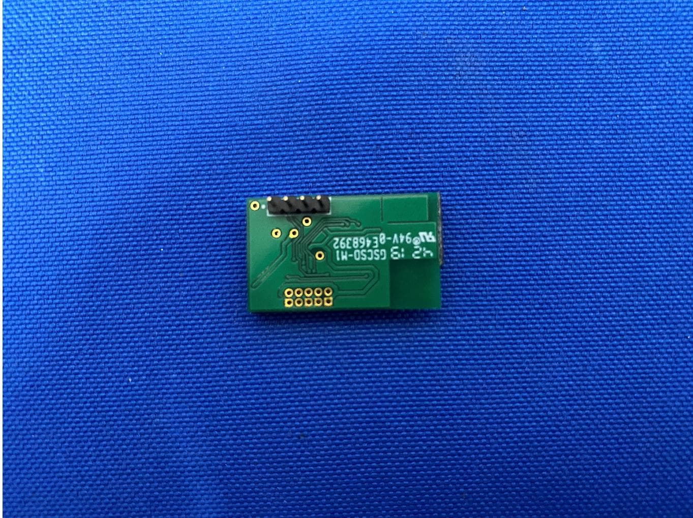
BRWSPMBT2000
Jun 09, 2020BT2000 Bluetooth Module
Equipment Class
DTS - Digital Transmission System