BRWDAMTX122.4 GHz Transceiver Module
Horizon Hobby, LLC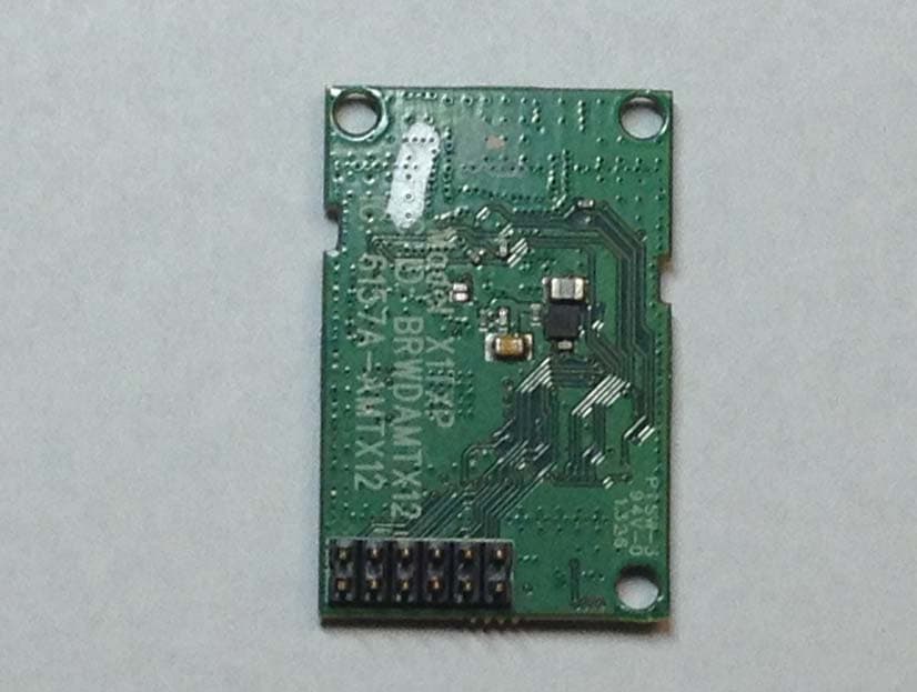
Click to zoom
Application Details
- Equipment Class
- DTS - Digital Transmission System
- Date of Grant
- Aug 19, 2013
- Application Purpose
- Original Equipment
- Date of Application
- Aug 19, 2013
- Equipment Note
- 2.4 GHz Transceiver Module
- Frequency Range
- 2402.00000000 - 2478.00000000
- Company
- Horizon Hobby, LLC
- Country
- United States
Documents & Files
Document Text
Text extracted from the exhibit documents filed with the FCC. Open a document above to read the original.
Users Manual
Page 1 of 4 X1TXP 2.4GHz DSSS Module User Manual. Horizon Hobby Inc., 4105 Fieldstone Rd Champaign, IL 61822 (408) 203 4408 1. Features 2.4GHz Direct Sequence Spread Spectrum (DSSS) radio transceiver module. Operates in the unlicensed worldwide ISM band (2.4 GHz to 2.483.5GHz) band Fully integrated power regulation with a wide input unregulated operating range 3V to 10V. Fully integrated local oscillator and 12MHz 20ppm reference crystal 200mA operating current Transmit power - 100mW EIRP Receive sensitivity up to -95dBm DSSS data rates up to 250kbps 1 mile operating range Full packet assembling and disassembling Auto transaction sequencer Fully buffered digital interface with high voltage tolerant inputs 2. Pin description Pin Number Name Description 1 GND Module Ground 2 VCE Power control monitoring 3 VIN Module DC Power 4 P21 Baseband CPU digital port P2.1 5 P33 Baseband CPU digital port P3.3 6 P17 Baseband CPU digital port P1.7 7 P32 Baseband CPU digital port P3.2 8 GND Module Ground 9 P30 Baseband CPU digital port P3.0 10 XRES Baseband CPU reset input 11 P11 Baseband CPU digital port P1.1 12 P10 Baseband CPU digital port P1.0 Page 2 of 4 3. Specifications Parameter Value Units Storage Temp -65 to 105 Degrees Celsius VDD 2.4 to 3.6 Volts Receive Sensitivity -95 dBm Transmit power (conducted) 18.5 dBm MAX Transmit power (radiated) 20 dBm MAX Idle current 1 mA Receive current 22 mA Transmit current 200 mA 4. Module User Requirements 4.1 This module must be integrated into a device where the user cannot access the antenna connector. 4.2 Only a 2.0dBi antenna can be used with this module. The antenna must meet and not exceed the gain and pattern of the supplied folded dipole antenna. 4.3 The device must contain the following permanent labeling on the exterior of the device as follows: Contains FCC ID: BRWDAMTX12 4.4 The user manual of the device must contain the following paragraph: Page 3 of 4 FCC Information This device complies with part 15 of the FCC rules. Operation is subject to the following two conditions: (1) This device may not cause harmful interference, and (2) this device must accept any interference received, including interference that may cause undesired operation. IC Information This device complies with Industry Canada license-exempt RSS standard(s). Operation is subject to the following two conditions: (1) this device may not cause interference, and (2) this device must accept any interference, including interference that may cause undesired operation of the device. CE Information This product contains a radio transmitter with wireless technology which has been tested and found to be compliant with the applicable regulations governing a radio transmitter in the 2.400 GHz to 2.4835 GHz frequency range. The following countries associated regulatory agencies recognizing the noted certifications for this product as authorized for sale and use are: UK DE DK NO SE FI EE LV LT PL Page 4 of 4 4.5 This module meets the requirements for a mobile device that may be used at separation distances of more than 20cm from the human body. It may be used in hand-held controllers that provide a separation distance of at least 5cm between the antenna and the body (excluding hands/wrists). The instructions to the user for the host device must include information requiring the product be used in a manner to ensure the appropriate separation (20cm or 5cm) between antenna and body and requiring that the transmitter not be collocated with another transm
Cover Letter(s)
Page 1 of 1 RP-7XXXL 12 East Devonwood SOLVING A WAVE OF EMI COMPLIANCE PROBLEMS Romeoville, IL 60446 ENTER August 5, 2013 Tel: (815) 293-0772 Page 1 of 1 Fax: (815) 293-0820 Federal Communications Commission Authorization and Evaluation Division 7435 Oakland Mills Rd. Columbia, MD 21046 Reference FCC ID: BRWAMTX12 Organization: Horizon Hobby, Inc. Long Term Confidentiality Horizon Hobby requests that the following materials be withheld from public inspection permanently under 47 C.F.R. 0.457 & 0.459: (1) Detailed Circuit Schematics of the EUT (2) Block Diagrams (3) EUT Description The above materials contain proprietary and confidential information not customarily released to the public. The public disclosure of these materials provides unjustified benefits to its competitors in the market. They are considered confidential trade secrets Authorized Signature Joseph Strzelecki Senior EMC Engineer Radiometrics Midwest Corporation Authorized Agent for Horizon Hobby, Inc.
Cover Letter(s)
12 East Devonwood SOLVING A WAVE OF EMI COMPLIANCE PROBLEMS Romeoville, IL 60446 August 5, 2013 Tel: (815) 293-0772 Fax: (815) 293-0820 Federal Communications Commission Authorization and Evaluation Division APPLICANT: Horizon Hobby, Inc. REFERENCE FCC ID: BRWDAMTX12 RE: Request for Modular Approval Industry Canada Authorization and Evaluation Division REFERENCE Industry Canada ID: 6157A-AMTX12 RE: Request for Modular Approval Radiometrics has been authorized by Horizon Hobby to act as an agent in the preparation of their submittal request for Modular Approval. Modular approval Requirements Characteristics: FCC Part 15 Item Requirement EUT Justification 1 Have its own RF shielding The RF portions of the module are completely contained within a metal shielding can. The module does not depend on any other shielding. 2 Have buffered modulation/data inputs (if such inputs are provided), All data communication with the module is digital. A microprocessor then converts the digital information into the analog RF signal. 3 Have it own power supply regulation The module has on-board voltage regulation which allows it to accept input power between 4-volts and 10-volts DC. 4 Meet the antenna requirements of Section 15.203 The module and antenna design is not user serviceable. It utilizes non-standard micro-coaxial connectors and antennas with approximate gain of 1.5 dBi. 5 Be tested in a stand-alone configuration, i.e., the antenna, AC or DC power and data input/output lines must be connected to the module but, the module must not be inside another case during testing Device was tested with an DC power supply. It had no additional shielding. 6 Be labeled with its own FCC ID number, and if the FCC ID is not visible when the module is installed inside another device, then the outside of the device into which the module is installed must also display a label referring to the enclosed module. The FCC ID label format is included in the filing. The product will always be inside another enclosure during actual use. A label will be placed on the outside of the product if the FCC ID is not visible Item Requirement EUT Justification 7 The modular transmitter is manufactured so that the user cannot influence the operation of the transmitter that will operate outside of the scope of the regulations. Frequency selection is controlled by the product’s software configuration, which is not user configurable or accessible. 8 Address compliance with the Commission's RF exposure limits in Sections 1.1310 and 2.1093. In addition, spread spectrum transmitters operating under Section 15.247 are required to address RF exposure compliance in accordance with Section 15.247(b)(4). Example Refer to RF exposure Exhibit. The transmitter meets MPE calculations of 47 CFR 1.1310. Modular approval Requirements Characteristics: RSS-Gen Section 7.1.1 Item RSS-Gen EUT Requirement EUT Justification (a) The module must be a complete radio transmitter with its own reference oscillator, antenna, etc. The only connectors to the module, if any, are power supply and modulation/data inputs. The module meets this requirement. (b) The module has its own RF shielding. The RF portions of the module are completely contained within a metal shielding can. The module does not depend on any other shielding. (c) The module must have buffered modulation/data input(s) (if such inputs are provided) to ensure that the module will comply with RSS-210 requirements under conditions of excessive data rates or over-modulation. All inputs to the module are buffered and processed through logic (d) The module has its own power supply regulation. This is to ensure that the module will comply with RSS-210 requirements regardless of the design of the power supplying circuitry in the host device which houses the module. All power supplies on the board, 3.05V, 1.73V, 1.15V, are provided/regulated from the PMIC. The PMIC receives power either from the battery or from the host interface (5V over USB). Refer to the Block Diagram. (e) The certification submission contains a detailed description of the configuration of all antennas that will be used with the module. Two ¼ wave dipole antenna are used. See theory of operation Item RSS-Gen Testing Requirement EUT Justification (a) The host device, as a stand-alone unit without any separately certified modules, complies with all applicable Radio Standards Specifications. The host device meets this requirement. (b) The host device and all the separately certified modules it contains jointly meet the RF exposure compliance requirements of RSS- 102, if applicable. Refer to RF exposure Exhibit. The transmitter meets RSS-102. The antenna gain is less than 6 dB (b) The host device complies with the certification labeling requirements of each of the modules it contains. The host device meets this requirement. This product will not be sold to the general public as a module. It will only be installed in Horizon Hobby products. Please do not hesitate to contact me if there are any further questions. Sincerely, Joseph Strzelecki, NCE Radiometrics Midwest Corporation Authorized Agent for Horizon Hobby E-Mail: [email protected]
External Photos
Authorized Agent: Radiometrics Midwest Corporation (815) 293-0772 External EUT Photographs Top of EUT Bottom of EUT: antenna attached Authorized Agent: Radiometrics Midwest Corporation (815) 293-0772 Rear side of Module
ID Label/Location Info
Authorized Agent: Radiometrics Midwest Corporation (815) 293-0772 ID Labeling/Location Drawing of label The dimensions of the labeling are 1.0x0.375 inches The labeling is silkscreen printed on the printed circuit board The text is white ink on green soldermask The labeling is permanent Photograph showing placement of labeling Model X1TXP FCC ID: BRWDAMTX12 IC: 6157-AMTX12
Internal Photos
Authorized Agent: Radiometrics Midwest Corporation (815) 293-0772 Internal EUT Photographs Photograph of PCB; Component Side, Shield removed Photograph of PCB; Foil Side
Test Report
Radiometrics Midwest Corporation - www.Radiomet.com Page 1 of 23 Electromagnetic Compatibility Test Report Tests Performed on a Horizon Hobby 2.4 GHz Transmitter Transciever, Model X1TXP Radiometrics Document RP-7619 Product Detail: FCC ID: BRWDAMTX12 IC: 6157A-AMTX12 Equipment type: DTS Test Standards: US CFR Title 47, Chapter I, FCC Part 15 Subpart C FCC Part 15 CFR Title 47: 2012 Industry Canada RSS-210, Issue 8: 2010 as required for Category I Equipment This report concerns: Original Grant for Certification FCC Part 15.247 Tests Performed For: Test Facility: Horizon Hobby Radiometrics Midwest Corporation 12 East Devonwood Romeoville, IL 60446 (815) 293-0772 Test Date(s): (Month-Day-Year) July 8 to 25, 2013 Document RP-7619 Revisions: Rev. Issue Date Affected Sections Revised By 0 August 7, 2013 Radiometrics Midwest Corporation www.radiomet.com Testing of the Horizon Hobby, Model X1TXP, 2.4 GHz Transmitter RP-7619 Rev. 0 Page 2 of 23 Table of Contents 1 ADMINISTRATIVE DATA .................................................................................................................... 3 2 TEST SUMMARY AND RESULTS ...................................................................................................... 3 2.1 RF Exposure Compliance Requirements ..................................................................................... 4 3 EQUIPMENT UNDER TEST (EUT) DETAILS ..................................................................................... 4 3.1 EUT Description ............................................................................................................................ 4 3.1.1 FCC Section 15.203 & RSS-GEN Antenna Requirements .................................................... 4 3.2 Related Submittals ........................................................................................................................ 4 4 TESTED SYSTEM DETAILS .............................................................................................................. 4 4.1 Tested System Configuration ....................................................................................................... 4 4.2 Special Accessories ...................................................................................................................... 5 4.3 Equipment Modifications ............................................................................................................... 5 5 TEST SPECIFICATIONS AND RELATED DOCUMENTS .................................................................. 5 6 RADIOMETRICS’ TEST FACILITIES .................................................................................................. 5 7 DEVIATIONS AND EXCLUSIONS FROM THE TEST SPECIFICATIONS ......................................... 6 8 CERTIFICATION ................................................................................................................................. 6 9 TEST EQUIPMENT TABLE ................................................................................................................ 6 10 TEST SECTIONS .............................................................................................................................. 7 10.1 Occupied Bandwidth ................................................................................................................... 7 10.2 Peak Output Power ................................................................................................................... 10 10.3 Power Spectral Density ............................................................................................................ 11 10.4 Band-edge Compliance of RF Conducted Emissions ............................................................... 11 10.5 Spurious RF Conducted Emissions at Antenna Port ................................................................ 11 10.6 Spurious Radiated Emissions (Restricted Band) ...................................................................... 18 10.6.1 Radiated Emissions Field Strength Sample Calculation .................................................... 18 10.6.2 Spurious Radiated Emissions Test Results ....................................................................... 19 Notice: This report must not be reproduced (except in full) without the written approval of Radiometrics Midwest Corporation. Radiometrics Midwest Corporation www.radiomet.com Testing of the Horizon Hobby, Model X1TXP, 2.4 GHz Transmitter RP-7619 Rev. 0 Page 3 of 23 1 ADMINISTRATIVE DATA Equipment Under Test: A Horizon Hobby, 2.4 GHz Transmitter Model: X1TXP Serial Number: none This will be referred to as the EUT in this Report Date EUT Received at Radiometrics: (Month-Day-Year) Test Date(s): (Month-Day-Year) July 8, 2013 July 8 to 25, 2013 Test Report Written By: Test Witnessed By: Joseph Strzelecki Senior EMC Engineer Jeff Walker Horizon Hobby Radiometrics’ Personnel Responsible for Test: Test Report Approved By Joseph Strzelecki Senior EMC Engineer NARTE EMC-000877-NE Chris W. Carlson Director of Engineering NARTE EMC-000921-NE 2 TEST SUMMARY AND RESULTS The EUT (Equipment Under Test) is a 2.4 GHz Transmitter, Model X1TXP, manufactured by Horizon Hobby. The detailed test results are presented in a separate section. The following is a summary of the test results. Emissions Tests Results Environmental Phenomena Frequency Range Basic Standard Test Result RF Radiated Emissions 30-25,000 MHz RSS-210 & FCC Part 15 Pass Occupied Bandwidth Test Fundamental Freq. RSS-210 & FCC Part 15 Pass Spread Spectrum Transmitter Requirements Environmental Phenomena Frequency Range FCC Section RSS- Section Test Result RF AC Mains Conducted Emissions 0.15 - 30 MHz 15.207 GEN; 7.2.2 Pass RF Radiated Emissions (Unintential Radiation Receive mode) 30-25,000 MHz 15.209 GEN; 7.2.5 Pass Time of Occupancy (Dwell Time) 2400 to 2483 MHz 15.247 a 210; A8.1 (2) Pass 6 dB Bandwidth Test 2400 to 2483 MHz 15.247 a 210; A8.1 (4) Pass 20 …
Text truncated - open the document above for the full version.
Test Setup Photos
Authorized Agent: Radiometrics Midwest Corporation (815) 293-0772 Test Setup Photographs Photographs of Radiated Emissions Test Setup Authorized Agent: Radiometrics Midwest Corporation (815) 293-0772 Photograph of Antenna Conducted Emissions Test Setup
Contact Information
Applicant
Jason Rosa(Lead Quality and Compliance Associate)
Test Firm
Radiometrics Midwest Corp.Joseph Strzelecki
Technical Specifications
| # | Rule Parts | Frequency Range | Power Output |
|---|---|---|---|
| 1 | 15C | 2.40 GHz - 2.48 GHz | 100.00 mW |
Other Applications from Horizon Hobby, LLC
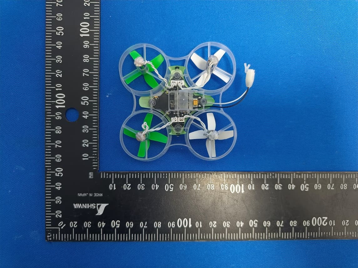
BRWBLH08701
Jul 29, 2023Inductrix RTF
Equipment Class
DTS - Digital Transmission System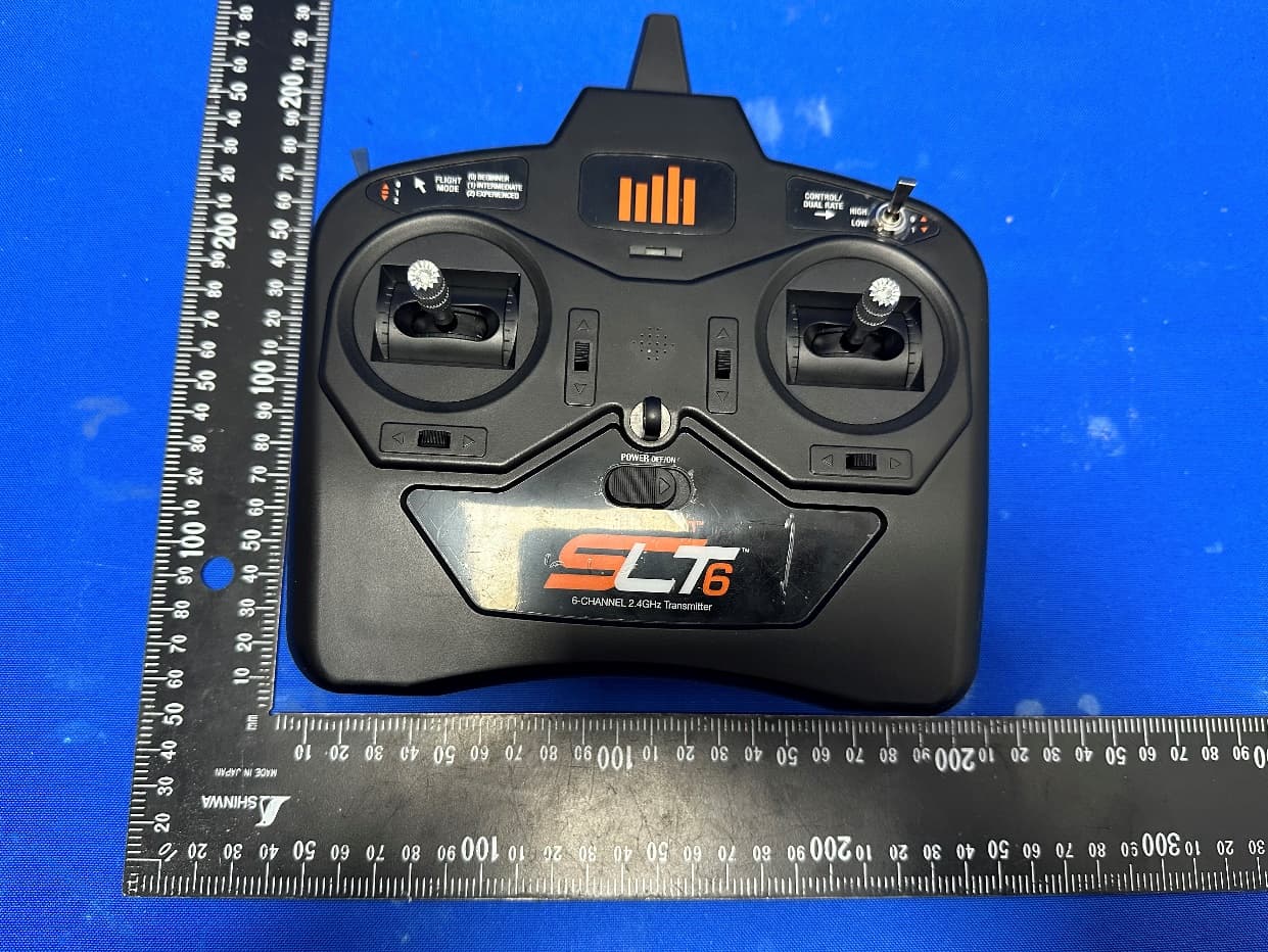
BRWSPMR1275
May 05, 2023SLT6
Equipment Class
DTS - Digital Transmission System
BRWSPMAR10360T
Oct 11, 2020AR10360T 10 Channel AS3X/SAFE Telemetry Receiver
Equipment Class
DSS - Part 15 Spread Spectrum Transmitter
BRWSPMAR10100T
Oct 11, 2020AR10100T 10 Channel Telemetry Receiver
Equipment Class
DSS - Part 15 Spread Spectrum Transmitter
BRWSPMSR6200A
Aug 11, 20206CH AVC surface receiver
Equipment Class
DXX - Part 15 Low Power Communication Device Transmitter