BRWPYTHONJR Python Pistol Grip AM Radio System
Horizon Hobby, LLC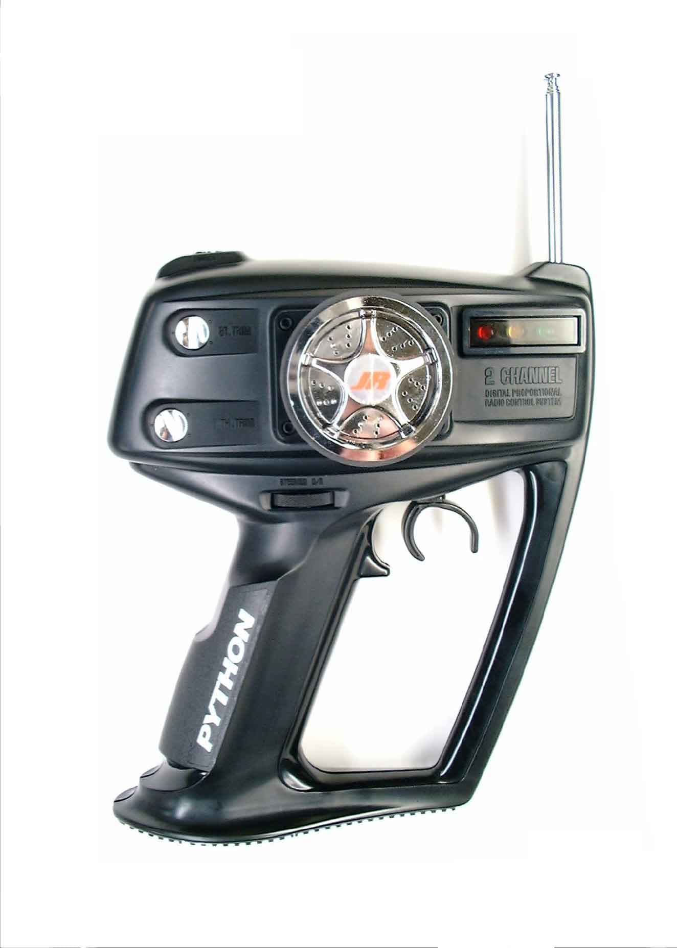
Click to zoom
Application Details
- Equipment Class
- TNB - Licensed Non-Broadcast Station Transmitter
- Date of Grant
- Nov 28, 2000
- Application Purpose
- Original Equipment
- Date of Application
- Oct 03, 2000
- Equipment Note
- JR Python Pistol Grip AM Radio System
- Frequency Range
- 75.41000000 - 75.99000000
- Company
- Horizon Hobby, LLC
- Country
- United States
Documents & Files
Document Text
Text extracted from the exhibit documents filed with the FCC. Open a document above to read the original.
Users Manual
1 2-CHANNEL DIGITAL PROPORTIONAL RADIO CONTROL SYSTEM INSTRUCTION MANUAL II. COMPONENTS AND SPECIFICATIONS Your JR Python Radio includes the following items: Transmitter ......................................................... NET-112L 2-Channel Receiver ................................................ NER-102 2 Servos ............................................................... Z250 x 2 Accessories ............ B.E.C. Switch Harness and Servo Accessories T RANSMITTER SPECIFICATIONS: P YTHONLED Antenna Output...................................................... 500mW Frequency ......................................................... 27/75 MHz Modulation .................................................................. AM Power Supply ...................................................... 9.6V D/C Dimensions .......................................... 8.15"x 7.00"x 3.35" Weight ..................................................................... 13 oz R ECEIVERSPECIFICATIONS: R102 Intermediate Frequency .......................................... 455KHz Power Supply ................................................ 4.8V-8.4V D/C Dimensions.......................................... 1.93"x 1.50"x 0.827" Weight ..................................................................... 1.3 oz S ERVOSPECIFICATIONS: Z250 Torque ......................................................... 49 in/oz. (6V) Speed .......................................................... .19 sec/60° (6V) Dimensions .......................................... 0.73"x 1.52"x 1.32" Weight ..................................................................... 1.5 oz BB ........................................................................ Bushing Motor ............................................................ 3-Pole Ferrite III. R/C SAFETY PRECAUTIONS For safe and reliable performance of your R/C model, please care- fully read and follow these guidelines: 1. Radio control models are not toys. They are capable of inflict- ing serious injury to people and property. Use caution at all times when operating your model. 2. You are responsible for the safe operation of your R/C model. You must properly install, test, and operate your model with a clear sense of that responsibility. Do not take risks that might endanger yourself or others. 3. Running an R/C car in the streets is very dangerous to both drivers and models. Avoid running your model in areas occupied by full-size automobiles. To locate areas where you can safely operate your model, contact your local hobby shop for R/C tracks or clubs in your area. 4. When running an R/C boat, keep it away from any swimmers, full-size boats, or wildlife. Also, watch carefully for fishing lines that can entangle the propeller. 5. Before operating your model, make sure your frequency is clear. If someone else is operating on the same frequency, both models will go out of control, possibly causing damage to the models, as well as others. 6. If at any time while operating your R/C model you sense abnormal model functioning, end your operation immedi- ately. Do not operate your model again until you are certain the problem has been corrected. CAUTION:Control of your model is impossible without suffi- cient voltage for the transmitter and receiver. A weak transmitter battery will decrease your range of operation and a weak receiver battery will slow servo movement and decrease your range of operation. Check your receiver pack voltage often to avoid losing control of your model. When using a model that operates both the electric motor and the receiver from the same battery (Battery Eliminating Circuitry or B.E.C.), you should discontinue use when the top speed sharply decreases or you will quickly lose control of your model. I. INTRODUCTION Congratulations on your purchase of the JR Python 2-channel radio control set which has been manufactured and assembled with the greatest care. We are confident that you will be delighted with your purchase. Please read the instructions thoroughly, noting all points before use, in order to avoid mistakes in handling and operation. Your NER-102 Receiver has Battery Eliminator Circuitry (B.E.C.). The receiver gets its power from the model’s NiCad battery pack, thus saving the weight of an additional receiver battery. NiCad batteries from 6V-8.4V (5-7 cells) can be used safely. Higher volt- age packs may damage the receiver and servos. ATTENTION:Make sure the male and female connectors have the correct polarity (+/–) before connecting. The servo lead and receiver case are molded so that the lead can only be inserted correctly. Be sure to orient the servo plug correctly for proper insertion. You may use a separate battery to power the receiver (such as for some electric boats or in gas-powered vehicles). A NiCad pack plugged into the BATT socket on your receiver will operate your receiver. You may also use alkaline batteries with an optional battery holder (part no. JRPA020). If you use a mechanical speed controller, please ensure that it has the correct connector for a B.E.C. system (red connector). See F IGUREA for a typical setup. Most electronic speed controllers are set up for B.E.C. operation and plug directly into your receiver (Function 2). See FIGUREB for a typical setup and check your speed controller’s manual for correct installation. You should use the black rubber servo cushions whenever possi- ble to decrease your servo’s sensitivity to vibration. IV. OPERATING YOUR MODEL It is important to learn the proper sequence for switching ON/OFF your radio system: BEFOREOPERATION: Switch on the transmitter, then the receiver. A FTEROPERATION:Switch off the receiver, then the transmitter. This ensures that you will always have a signal to the receiver, and your R/C model will not operate out of control when you turn off the transmitter. V. INSTALLATION B E C B E C FIGUREA – Connections to B.E.C. receiver with mechanical speed controler. NiCad battery, s…
Text truncated - open the document above for the full version.
External Photos
FCC ID# BRWPYTHON page 11 FCC ID# BRWPYTHON page 15 FCC ID:BRWPYTHON SAMPLE OF FCC ID LABEL AND LOCATION ON TX ACTUAL LABEL WILL HABE THE FCC ID NUMBER BRWPYTHON
ID Label/Location Info
October 6,2000 Federal Communications Commission Equipment Authorization Division, Applications Processing Branch 7435 Oakland Mills Road Columbia, MD 21046 RE) FCC ID: BRWPYTHON (EA98947) To whom it may concern; Please refer to the additional information listed below while reviewing the BRWPYTHON System. 1) Section 95.645 (b) states that plug-in crystals must not be accessible to the user. Indicate whether or not crystals are accessible to the user. Although the transmitter crystal is visible from the back of the transmitter, each crystal is glued in place prior to shipment making it a permanent installation. Consumer removal of the crystal will normally result in damage to the crystal. Therefore, frequency changes are done at the service center only. 2) The Manual must contain warnings per section 95.653 A) Please refer to the manual attachment for this information B) All content for operation is contained in the instruction manual. 1) All instructions are contained in the instruction manual. 2) There are no adjustments accessible to the user that would be in violation with the FCC rules, except as noted in the section #3 below. 3) Noted. We will be adding the following information to the instruction manual under “Frequency Chart”: “Note: The Federal Communications Commission (FCC) requires that changes in radio frequency must be performed by an authorized service technician only (Horizon Service Center). Any frequency changes made by a non-certified technician may result in a violation of the FCC rules” 4) This section is not applicable to our use. If there is any further information required, please contact me directly at: Horizon Hobby Distributors ATTN: Len Sabato Fax: 217-355-0058 Phone: 217-352-1958 Ext. 454 [email protected] Best Regards ; Len Sabato
ID Label/Location Info
FCC ID# BRWPYTHON page 15 FCC ID:BRWPYTHON SAMPLE OF FCC ID LABEL AND LOCATION ON TX ACTUAL LABEL WILL HABE THE FCC ID NUMBER BRWPYTHON
Internal Photos
FCC ID# BRWPYTHON page 12 FCC ID# BRWPYTHON page 13 FCC ID# BRWPYTHON page 14
Schematics
FCC ID# BRWPYTHON Figure 5.1 Transmitter Block Diagram page 8 FCC ID# BRWPYTHON Figure 5.2 Transmitter Schematic Diagram page 9
Test Report
A-021-00-C Page 1 of 21 KEC Ikoma Testing Laboratory 12128 Takayama-cho Ikoma-city Nara 630-0101 Japan Designated by Ministry of international Trade and industry KANSAI ELECTRONIC INDUSTRY DEVELOPMENT CENTER HEAD OFFICE IKOMA TESTING LABORATORY 6-8-7 NISHITENMA 12128 TAKAYAMA-CHO KITA-KU OSAKA 530-0047 JAPAN IKOMA-CITY NARA 630-0101 JAPAN Corporate Juridical Person TEST REPORT Report No.A-021-00-CDate: 21 June 2000 This test report is to certify that the tested device properly complies with the requirements of: FCC Rules and Regulations Part 95 : Radio Control (R/C) Radio Service. The tests necessary to show compliance to the requirements were performed and these results met the specifications of requirement. The results of this report should not be construed to imply compliance of equipment other than that, which was tested. Unless the laboratory permission, this report should not be copied in part. 1. Applicant Company Name:JAPAN REMOTE CONTROL CO., LTD. Mailing Address:2-2-12, EIWA, HIGASHIOSAKA-CITY, OSAKA, 577-0809 JAPAN 2. Identification of Tested Device Type of Device:Radio Control (R/C) Radio Service. Kind of Equipment Authorization:: DoC : Certification: Verification FCC ID:BRWPYTHON Device Name:AM 2 CHANNEL TRANSMITTER Trade Name: JR PROPO Model Number: PYTHON Serial Number:No.1: Prototype : Pre-production : Production Date of Manufacture:May, 2000 3. Test Items and Procedure : Measurement of RF Power Output (Substitution Method) : Modulation Characteristics : Emission Bandwidth : Measurement of Field Strength of Spurious Radiation : Frequency Stability Measurement Above all tests were performed under: FCC Part 2 Sec2.1046, Sec2..1047, Sec2.1049, Sec2.1053, Sec2.1055 and Sec2.1057. : without deviation, : with deviation(details are found inside of this report) 4. Date of Test Receipt of Test Sample: 1 June 2000 Test Completed on: 19 June 2000 Eizo Hariya General Manager of Ikoma Testing Laboratory A-021-00-C Page 2 of 21 KEC Ikoma Testing Laboratory 12128 Takayama-cho Ikoma-city Nara 630-0101 Japan Table of Contents 1. GENERAL INFORMATION.................................................................................................................3 1.1 Product Description...........................................................................................................................3 1.2 Description for Equipment Authorization........................................................................................3 1.3 Test Facility........................................................................................................................................3 2. TESTED SYSTEM................................................................................................................................4 2.1 Test Mode...........................................................................................................................................4 2.2 Block Diagram of EUT System...........................................................................................................4 2.3 List of EUT System............................................................................................................................5 2.4 List of Antenna..................................................................................................................................5 3. RF POWER OUTPUT...........................................................................................................................6 3.1 Reference Rule and Specification......................................................................................................6 3.2 Test Configuration.............................................................................................................................6 3.3 Test Procedure....................................................................................................................................7 3.4 Test Results........................................................................................................................................8 4. MODULATION CHARACTERISTICS.................................................................................................9 4.1 Reference Rule and Specification......................................................................................................9 4.2 Test Results........................................................................................................................................9 5. EMISSION BANDWIDTH.................................................................................................................10 5.1 Reference Rule and Specification....................................................................................................10 5.2 Test Configuration...........................................................................................................................10 5.3 Test Results.......................................................................................................................................11 6. FIELD STRENGTH OF SPURIOUS RADIATION...........................................................................14 6.1 Reference Rule and Specification....................................................................................................14 6.2 Test Procedure..................................................................................................................................14 6.3 Test Configuration...........................................................................................................................15 6.4 Photographs of EUT System Configuration...................................................................................16 6.5 Test Results......................................................................................................................................18 7. FREQUENCY STABILITY MEASUREMENT..................…
Text truncated - open the document above for the full version.
Test Report
Page 1 Technical Report Transmitter Model PYTHON FCC ID# BRWPYTHON T A B L E O F C O N T E N T S 1.0 INTRODUCTION 1.1 Definition 1.2 Application 1.3 Construction 2.0 ENCODER THEORY OF OPERATION 3.0 THEORY OF OPERATION 3.1 General 3.2 Block Diagram 4.0 FAILURE ANALYSIS 5.0 APPENDICES 5.1 Transmitter Block Diagram 5.2 Transmitter Schematic Diagram 5.3 Transmitter Photographs and ID Labels 5.4 Transmitter Tune-Up Procedure 5.5 Quarts Crystal Specifications 5.6 Test Data Page 2 Technical Report Transmitter Model PYTHON FCC ID# BRWPYTHON 1.0 INTRODUCTION 1.1 Definition The Model PYTHON is a transmitter for the Remote Control (R/C) of models such as cars, boats, etc. This Transmitter is for AM System, available for the PPM(Pulse Position Modulation). This Transmitter is a part of the HORIZON HOBBY DISTRIBUTORS, INC. AM"family" of Remote Control Transmitters which at this time consists of: Transmitter Model # FCC ID # Beat GEAR NET-102 BRWNET102 PYTHON NET-112 BRWNET-112 Separate Applications for each transmitters and for the receivers are submitted as required by the Commission. The Manufacturer, Japan Remote Control Company (JR), manufactures all transmitters and receivers. The AM family of R/C systems is exported by JR to the United States of America, and several European and Asian Countries. The Applicant for this Equipment Authorization, HORIZON HOBBY DISTRIBUTORS, INC. will, following receipt of Grant of Equipment Authorization, import only those versions of these R/C radios which are allowed for use in the USA under the Rules and Regulations of the Federal Communications. The 75 - 76 MHz version of this transmitter is the subject of this Application; these are the units which will be offered for sale to the general public. Page 3 Technical Report Transmitter Model PYTHON FCC ID# BRWPYTHON 1.2 Application The Model PYTHON R/C transmitter utilizes "Amplitude Modulation" to convey the PPM encoded position of its control handle and trigger switches to its companion R/C receiver, where the PPM encoded pulse train is demodulated, decoded, and supplied to a number of servo-mechanisms for positioning of control surfaces, throttle etc. on the model. Both transmitter and receiver are very narrow band units; they have been designed to comply with the European requirements of 10 KHz channel spacing. 1.3 Construction The Model PYTHON Transmitter all consists of a plastic case. (Reference is made to Fig. 5.1, Transmitter Block Diagram) * control handle and trigger * a 8cells dry battery * an analog-to-digital converter (ADC) * a microprocessor to create the PPM pulse train (TMP87C408N) * a modulator driver stage * a RF power stage * a telescopic antenna This Transmitter is to be made available by the importer only on those carrier frequencies in the 75 - 76 MHz frequency band which are at present authorized for R/C use. Page 4 Technical Report Transmitter Model PYTHON FCC ID# BRWPYTHON 2.0 ENCODER THEORY OF OPERATION Reference is made to Figure 5.1, Transmitter Block Diagram. The functions of the encoder are to: * accept the analog voltages from the control inputs (joysticks, toggle switch). * process the analog voltages to create control mixing, adding, reversing, etc., as desired by the user. * sample these voltages in a cyclic rhythm under control of the system's internal timing generator. (This process is called commutation.) * process these analog voltages into binary weighted digital control words by means of an Analog-to-Digital Converter (ADC). * store these digital representations of the analog control input into a temporary memory (RAM). * supply this serial data stream to a buffer-driver for modulation of the RF Transmitter. * provide "housekeeping" of the encoding process by means of a quarts crystal controlled internal clock. * provide supply voltages to the RF section (Vcc = 12V battery voltage). The entire program which controls the timing housekeeping, parallel-to-serial conversion process, and insertion of synchronization words and error detection codes is governed by a Central Processing Unit (CPU) under control by an internally stored program residing in Read-Only Memory (ROM). The CPU, RAM and ROM are all part of a single-chip microprocessor. Resolution of the Analog-to-Digital conversion process is eight (8) bits for a control accuracy of 1:2 8 Page 5 Technical Report Transmitter Model PYTHON FCC ID# BRWPYTHON 3.0 THEORY OF OPERATION 3.1 General Reference is made to Figure 5.1, Transmitter Block Diagram. The HORIZON HOBBY DISTRIBUTORS, INC. Model PYTHON R/C Transmitter is handle and trigger type Transmitter. It operates on any of the R/C frequency (Channels) allowed by the Commission in the 75 -76 MHz frequency band. Selection of the desired RF channel is made by Quarts crystal. 3.2 Block Diagram (Reference is made to Figure 5.1) The (up to) four control potentiometers are at the right side of the schematic drawing. The control potentiometer, which is mechanically coupled to the control handle and trigger, is supplied with the regulated 5.0V voltage. The wiper on this pot is exactly centered in the neutral control stick position. All analog processing is performed as deviations from this center (reference) voltage. After the mixing of each channel, control voltage is changed to Pulse Train, through encoder circuit. The oscillation is oscillated by Transister Q51 with Third-over-tone, 37.5 MHz then, is dubled by Dobrer Amp. And Transister Q53 on 2nd stage to reach 75 MHz. After this, it is amplified by power Amp. Transister Q52a, and is supplied to the antenna through band pass filter. Page 6 Technical Report Transmitter Model PYTHON FCC ID# BRWPYTHON 4.0 FAILURE ANALYSIS A failure analysis was conducted to ascertain that single-component failure will not result in unauthorized radiation. It should be noted that component failure would result in return of the unit to the factory, or to an authorized repair station. (Reference is made to Figure 5.2, Transmitter Schematic Diagram) Fa…
Text truncated - open the document above for the full version.
Test Report
Page 1 Technical Report Transmitter Model PYTHON FCC ID# BRWPYTHON T A B L E O F C O N T E N T S 1.0 INTRODUCTION 1.1 Definition 1.2 Application 1.3 Construction 2.0 ENCODER THEORY OF OPERATION 3.0 THEORY OF OPERATION 3.1 General 3.2 Block Diagram 4.0 FAILURE ANALYSIS 5.0 APPENDICES 5.1 Transmitter Block Diagram 5.2 Transmitter Schematic Diagram 5.3 Transmitter Photographs and ID Labels 5.4 Transmitter Tune-Up Procedure 5.5 Quarts Crystal Specifications 5.6 Test Data Page 2 Technical Report Transmitter Model PYTHON FCC ID# BRWPYTHON 1.0 INTRODUCTION 1.1 Definition The Model PYTHON is a transmitter for the Remote Control (R/C) of models such as cars, boats, etc. This Transmitter is for AM System, available for the PPM(Pulse Position Modulation). This Transmitter is a part of the HORIZON HOBBY DISTRIBUTORS, INC. AM"family" of Remote Control Transmitters which at this time consists of: Transmitter Model # FCC ID # Beat GEAR NET-102 BRWNET102 PYTHON NET-112 BRWNET-112 Separate Applications for each transmitters and for the receivers are submitted as required by the Commission. The Manufacturer, Japan Remote Control Company (JR), manufactures all transmitters and receivers. The AM family of R/C systems is exported by JR to the United States of America, and several European and Asian Countries. The Applicant for this Equipment Authorization, HORIZON HOBBY DISTRIBUTORS, INC. will, following receipt of Grant of Equipment Authorization, import only those versions of these R/C radios which are allowed for use in the USA under the Rules and Regulations of the Federal Communications. The 75 - 76 MHz version of this transmitter is the subject of this Application; these are the units which will be offered for sale to the general public. Page 3 Technical Report Transmitter Model PYTHON FCC ID# BRWPYTHON 1.2 Application The Model PYTHON R/C transmitter utilizes "Amplitude Modulation" to convey the PPM encoded position of its control handle and trigger switches to its companion R/C receiver, where the PPM encoded pulse train is demodulated, decoded, and supplied to a number of servo-mechanisms for positioning of control surfaces, throttle etc. on the model. Both transmitter and receiver are very narrow band units; they have been designed to comply with the European requirements of 10 KHz channel spacing. 1.3 Construction The Model PYTHON Transmitter all consists of a plastic case. (Reference is made to Fig. 5.1, Transmitter Block Diagram) * control handle and trigger * a 8cells dry battery * an analog-to-digital converter (ADC) * a microprocessor to create the PPM pulse train (TMP87C408N) * a modulator driver stage * a RF power stage * a telescopic antenna This Transmitter is to be made available by the importer only on those carrier frequencies in the 75 - 76 MHz frequency band which are at present authorized for R/C use. Page 4 Technical Report Transmitter Model PYTHON FCC ID# BRWPYTHON 2.0 ENCODER THEORY OF OPERATION Reference is made to Figure 5.1, Transmitter Block Diagram. The functions of the encoder are to: * accept the analog voltages from the control inputs (joysticks, toggle switch). * process the analog voltages to create control mixing, adding, reversing, etc., as desired by the user. * sample these voltages in a cyclic rhythm under control of the system's internal timing generator. (This process is called commutation.) * process these analog voltages into binary weighted digital control words by means of an Analog-to-Digital Converter (ADC). * store these digital representations of the analog control input into a temporary memory (RAM). * supply this serial data stream to a buffer-driver for modulation of the RF Transmitter. * provide "housekeeping" of the encoding process by means of a quarts crystal controlled internal clock. * provide supply voltages to the RF section (Vcc = 12V battery voltage). The entire program which controls the timing housekeeping, parallel-to-serial conversion process, and insertion of synchronization words and error detection codes is governed by a Central Processing Unit (CPU) under control by an internally stored program residing in Read-Only Memory (ROM). The CPU, RAM and ROM are all part of a single-chip microprocessor. Resolution of the Analog-to-Digital conversion process is eight (8) bits for a control accuracy of 1:2 8 Page 5 Technical Report Transmitter Model PYTHON FCC ID# BRWPYTHON 3.0 THEORY OF OPERATION 3.1 General Reference is made to Figure 5.1, Transmitter Block Diagram. The HORIZON HOBBY DISTRIBUTORS, INC. Model PYTHON R/C Transmitter is handle and trigger type Transmitter. It operates on any of the R/C frequency (Channels) allowed by the Commission in the 75 -76 MHz frequency band. Selection of the desired RF channel is made by Quarts crystal. 3.2 Block Diagram (Reference is made to Figure 5.1) The (up to) four control potentiometers are at the right side of the schematic drawing. The control potentiometer, which is mechanically coupled to the control handle and trigger, is supplied with the regulated 5.0V voltage. The wiper on this pot is exactly centered in the neutral control stick position. All analog processing is performed as deviations from this center (reference) voltage. After the mixing of each channel, control voltage is changed to Pulse Train, through encoder circuit. The oscillation is oscillated by Transister Q51 with Third-over-tone, 37.5 MHz then, is dubled by Dobrer Amp. And Transister Q53 on 2nd stage to reach 75 MHz. After this, it is amplified by power Amp. Transister Q52a, and is supplied to the antenna through band pass filter. Page 6 Technical Report Transmitter Model PYTHON FCC ID# BRWPYTHON 4.0 FAILURE ANALYSIS A failure analysis was conducted to ascertain that single-component failure will not result in unauthorized radiation. It should be noted that component failure would result in return of the unit to the factory, or to an authorized repair station. (Reference is made to Figure 5.2, Transmitter Schematic Diagram) Fa…
Text truncated - open the document above for the full version.
Contact Information
Applicant
Jason Rosa(Lead Quality and Compliance Associate)
Technical Specifications
| # | Rule Parts | Frequency Range | Power Output | Emission | Tolerance |
|---|---|---|---|---|---|
| 1 | 95 | 75.41 MHz - 75.99 MHz | 35.00 mW | 4K00A1D | 0.0020000000 % |
Other Applications from Horizon Hobby, LLC
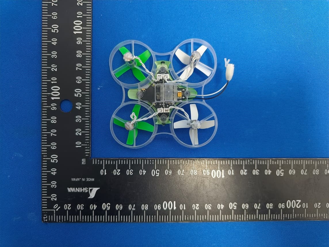
BRWBLH08701
Jul 29, 2023Inductrix RTF
Equipment Class
DTS - Digital Transmission System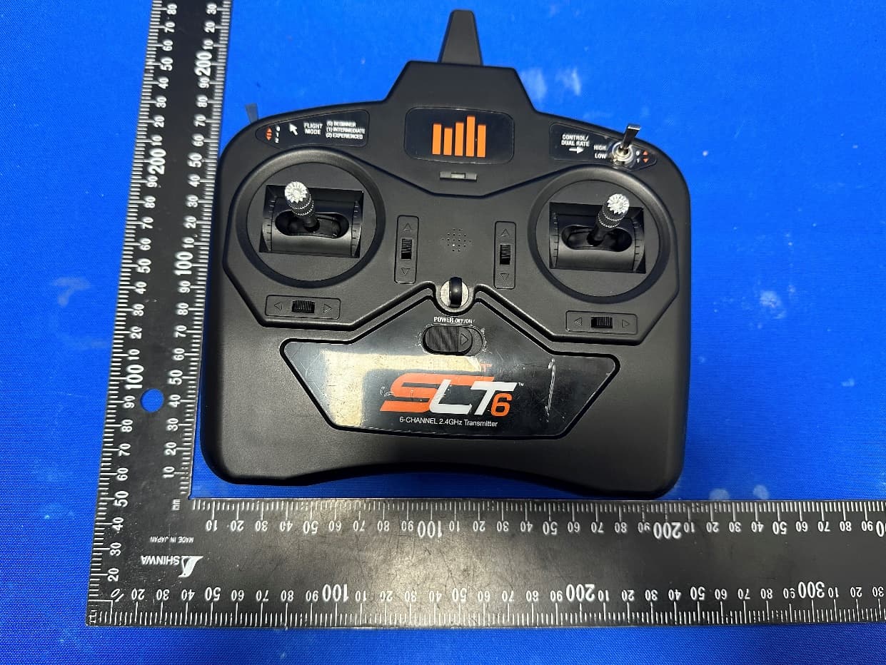
BRWSPMR1275
May 05, 2023SLT6
Equipment Class
DTS - Digital Transmission System
BRWSPMAR10360T
Oct 11, 2020AR10360T 10 Channel AS3X/SAFE Telemetry Receiver
Equipment Class
DSS - Part 15 Spread Spectrum Transmitter
BRWSPMAR10100T
Oct 11, 2020AR10100T 10 Channel Telemetry Receiver
Equipment Class
DSS - Part 15 Spread Spectrum Transmitter
BRWSPMSR6200A
Aug 11, 20206CH AVC surface receiver
Equipment Class
DXX - Part 15 Low Power Communication Device Transmitter