BRWXP662JR XP662 6 Channel FM Radio System
Horizon Hobby, LLC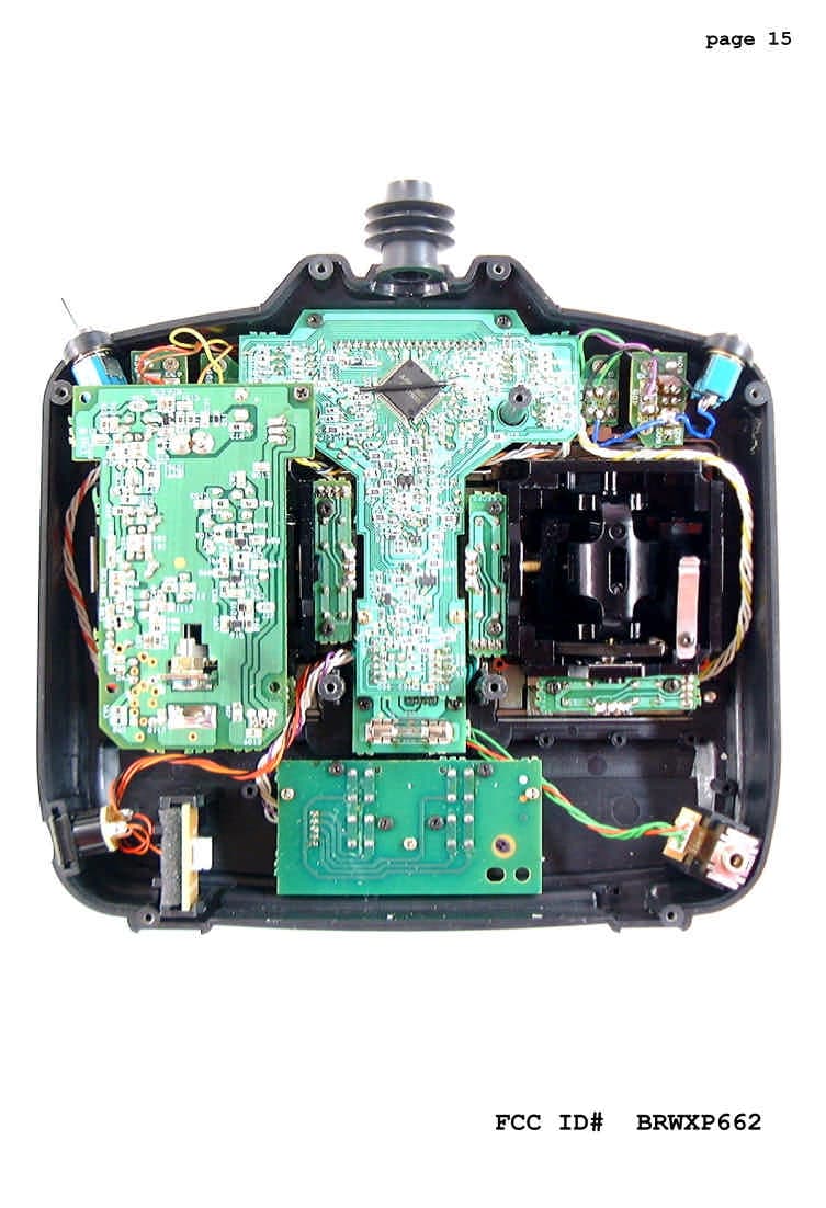
Click to zoom
Application Details
- Equipment Class
- TNB - Licensed Non-Broadcast Station Transmitter
- Date of Grant
- May 12, 2002
- Application Purpose
- Original Equipment
- Date of Application
- Feb 06, 2002
- Equipment Note
- JR XP662 6 Channel FM Radio System
- Frequency Range
- 72.01000000 - 72.99000000
- Company
- Horizon Hobby, LLC
- Country
- United States
Documents & Files
Document Text
Text extracted from the exhibit documents filed with the FCC. Open a document above to read the original.
Users Manual
6-CHANNEL COMPUTER RADIO INSTRUCTION MANUAL FOR AIRPLANE AND HELICOPTER 3984 JR XP662 Manual 1/21/02 1:11 PM Page 1 3984 JR XP662 Manual 1/21/02 1:11 PM Page 2 3 XP662 MANUAL Table of Contents TABLE OF CONTENTS I. INTRODUCTION Introduction to the XP662 Radio System4 Quick Start (Airplane)5 Quick Start (Helicopter)7 1.Using This Manual9 2.Features9 2.1 Transmitter Features9 2.2 Receiver Features9 2.3Servo Features10 2.4Servo Layout10 3.Specifications11 3.1 System Specifications11 3.2 Transmitter Specifications11 3.3 Servo Specifications11 3.4 Receiver Specifications12 3.5 Charger Specifications12 3.6 Airborne Battery Pack12 4.Battery Charging13 4.1 Transmitter/Receiver13 4.2 Charger13 5.Trainer System14 II. AIRPLANE SECTION 1. Transmitter Controls15 1.1 Control Identification and Location15 1.2 Digital Trim Levers15 1.3 Receiver Channel Assignment/Transmitter Throttle ATL16 1.4 Transmitter Rear16 1.5 Control Stick Length Adjustment17 1.6 Direct Servo Control (DSC)17 1.7Neck Strap Attachment17 2. Connections18 2.1 Installation Requirements18 2.2 Connections18 3.Key Input and Display19 4.Battery Alarm and Display19 5.Input Mode and Function20 5.1 Normal Display20 5.2 Direct Trim Access Display20 5.3 System Mode20 5.4 Function Mode21 5.5 Throttle Cut21 6.Functions (System Mode)22 6.1 Model Type Selection22 6.2 Data Reset23 6.3 Dual Rate Switch Selection24 6.4 Wing Type Selection25 6.5 Model Selection27 6.6Model Name Entry28 6.7Modulation Select29 6.8Fail-Safe/Hold 30 6.9Fail-Safe/Hold Function in Z-PCM Modulation30 6.10Fail-Safe/Hold Function in S-PCM Modulation 32 7.Functions (Function Mode)34 7.1Servo Reversing34 7.2Dual Rate35 7.3Exponential36 7.4 Sub-Trim37 7.5 Travel Adjustment38 7.6 Aileron-to-Rudder Mixing39 7.7Elevator-to-Flap Mixing41 7.8 Differential43 7.9Flap-to-Elevator Offset Trim44 7.10Programmable Mixing (A, B, C)45 8.Data Sheet48 III. HELICOPTER SECTION 1. Transmitter Controls49 1.1 Control Identification and Location49 1.2 Receiver Channel Assignment/Transmitter Throttle ATL49 1.3 Transmitter Rear50 1.4 Control Stick Length Adjustment51 1.5 Direct Servo Control (DSC)51 1.6Neck Strap Attachment51 2.Connections52 2.1 Installation Requirements52 2.2 Connections52 3.Key Input and Display53 4.Battery Alarm and Display53 5.Input Mode and Function54 5.1 Normal Display54 5.2 System Mode54 5.3 Function Mode55 6.Functions (System Mode)56 6.1 Model Type Selection56 6.2 Data Reset57 6.3 Dual Rate Switch Selection58 6.4 Gear/Gyro Switch Selection59 6.5 Model Selection60 6.6Model Name Entry61 6.7Modulation Select62 6.8Fail-Safe/Hold63 6.9Fail-Safe/Hold Function in Z-PCM Modulation63 6.10Fail-Safe/Hold Function in S-PCM Modulation65 7.Functions (Function Mode)67 7.1 Servo Reversing67 7.2 Dual Rate68 7.3Exponential69 7.4 Sub-Trim70 7.5 Travel Adjustment71 7.6Throttle Hold72 7.7 Pitch Curve73 7.8 Throttle Curve74 7.9 Revolution Mixing75 7.10Programmable Mixing (A)76 7.11CCPM Swashplate mixing79 7.12CCPM Servo Connections80 7.13How 120 CCPM works81 8.Data Sheet83 IV. IMPORTANT INFORMATION 1. General Notes93 2. Daily Flight Checks93 3. Warranty Coverage94 4. Repair Service Instructions94 5.Frequency Chart95 3984 JR XP662 Manual 1/21/02 1:11 PM Page 3 4 XP662 MANUAL Introduction Included with the XP662 Radio System is a switch/function decal sheet. These decals have been provided as a guide to specific switch positions, functions, and abbreviations used when operating the XP662. The four small decals help identify switch positions and use for helicopter and aircraft modes. The large decal at the bottom of the sheet gives abbreviations and definitions for all of the aircraft and helicopter functions. The functions decal will prove to be a helpful guide for making program changes to your XP662 both in the shop and at the flying field. We strongly encourage all prospective and current R/C aircraft pilots join the Academy of Model Aeronautics. The AMA is a non-profit organization which provides services to model aircraft pilots. As an AMA member you will receive a monthly magazine entitled Model Aviation, as well as a liability insurance plan to cover against possible accident or injury. All AMA charter aircraft clubs require individuals to hold a current AMA sporting license prior to operation of their models. For further information you can contact the AMA at: Academy of Model Aeronautics 5151 East Memorial Drive Muncie, IN 47302 (317) 287-1256 Thank you for purchasing the JR XP662 6-Channel Radio System. This unit has been designed to provide the modeler with a high quality, user friendly radio system that can be depended upon for years to come. It is important that you carefully read this manual before attempting to operate your XP662 System. Please pay particular attention to Page 13, Chapter 4 Charging Your XP662 Radio System, prior to Installing. XP662 SWITCH FUNCTION DECAL SHEET AMA INFORMATION FLAP UP DOWN OFF ON MIX ORGEAR DOWN UP OFF ON MIX OR THROTTLE HOLD NORMAL HOLD FLIGHT MODE NORMAL STUNT 72MHz FM TX REV – Servo Reversing AIRPLANE D/R – Dual Rates SB-TRIM – Sub-Trim TRV ADJ – Travel Adjustment MIX A-R – Ailer./Rudder Mixing MIX E-F – Elevator/Flap Mixing OFFSET – Landing Elev. Offset REV – Servo Reversing D/R – Dual Rates SB-TRIM – Sub-Trim HLD – Throttle Hold HELICOPTER TRV ADJ – Travel Adjustment PLN P2N PHN PLS P2S PHS PLH P2H PHH TLN T2N THN TLS T2S MIX RVU RVD OFFSET – Rudder Offset – Pitch Low Normal – Pitch Med. Normal – Pitch High Normal – Pitch Low Stunt – Pitch Med. Stunt – Pitch High Stunt – Pitch Low Hold – Pitch Med. Hold – Pitch High Hold – Throttle Low Norm. – Throttle Med. Norm. – Throttle High Norm. – Throttle Low Stunt – Throttle Med. Stunt – Revo Mixing – Revo Mixing Up – Revo Mixing Down DECAL SHEET HELICOPTER DECAL POSIITON Top View (Mode II) AIRPLANE DECAL POSITION Top View (Mode II) REAR DECAL POSITION Airplane and Helicopter INTRODUCTION TO THE XP662 RADIO SYSTEM • Introduction XP662 FUNCTION GUIDE TX BACK HELI TOP LEFT NORMAL STUNT FLIGHT MODE NORMAL STUNT T…
Text truncated - open the document above for the full version.
Cover Letter(s)
February 7, 2002 Federal Communications Commission Equipment Authorization Division, Applications Processing Branch 7435 Oakland Mills Road Columbia, MD 21046 RE) FCC ID: BRWXP662 (EA673213) To whom it may concern; Please refer to the additional information listed below while reviewing the BRWXP662 System. 1) Section 95.645 (b) states that plug-in crystals must not be accessible to the user. Indicate whether or not crystals are accessible to the user. Although the transmitter crystal is visible from the back of the transmitter, each crystal is glued in place prior to shipment making it a permanent installation. Consumer removal of the crystal will normally result in damage to the crystal. Therefore, frequency changes are done at the service center only. 2) The Manual must contain warnings per section 95.653 A) Please refer to the manual attachment for this information B) All content for operation is contained in the instruction manual. 1) All instructions are contained in the instruction manual. 2) There are no adjustments accessible to the user that would be in violation with the FCC rules. 3) This section is not applicable to our use. If there is any further information required, please contact me directly at: Horizon Hobby Distributors ATTN: Len Sabato Fax: 217-355-0058 Phone: 217-403-3588 [email protected]
External Photos
Page 1 Technical Report Transmitter Model XP662 FCC ID# BRWXP662 T A B L E O F C O N T E N T S 1.0 INTRODUCTION 1.1 Definition 1.2 Application 1.3 Construction 2.0 ENCODER THEORY OF OPERATION 3.0 THEORY OF OPERATION 3.1 General 3.2 Block Diagram 4.0 FAILURE ANALYSIS 5.0 APPENDICES 5.1 Transmitter Block Diagram 5.2 Transmitter Schematic Diagram 5.3 Transmitter Photographs and ID Labels 5.4 Transmitter Tune-Up Procedure 5.5 Quarts Crystal Specifications 5.6 Test Data Page 2 Technical Report Transmitter Model XP662 FCC ID# BRWXP662 1.0 INTRODUCTION 1.1 Definition The Model XP662 is a transmitter for the Remote Control (R/C) of models such as airplane, helicopters,etc. This Transmitter is for FM System, available for the PPM(Pulse Position Modulation) and PCM (Pulse Code Modulation). This Transmitter is a part of the HORIZON HOBBY DISTRIBUTORS, INC. PPM and PCM "family" of Remote Control Transmitters which at this time consists of: Transmitter Model # FCC ID # XP-642 BRWXP-642 Separate Applications for each transmitters and for the receivers are submitted as required by the Commission. The Manufacturer, Japan Remote Control Company (JR), manufactures all transmitters and receivers. The PPM family of R/C systems is exported by JR to the United States of America, and several European and Asian Countries. The Applicant for this Equipment Authorization, HORIZON HOBBY DISTRIBUTORS, INC. will, following receipt of Grant of Equipment Authorization, import only those versions of these R/C radios which are allowed for use in the USA under the Rules and Regulations of the Federal Communications. The 72 - 73 MHz version of this transmitter is the subject of this Application; these are the units which will be offered for sale to the general public. Page 3 Technical Report Transmitter Model XP662 FCC ID# BRWXP662 1.2 Application The Model XP662 R/C transmitter utilizes " Frequency Modulation" to convey the PPM and PCM encoded position of its control sticks (joysticks) and toggle switches to its companion R/C receiver, where the PPM and PCM encoded pulse train is demodulated, decoded, and supplied to a number of servo-mechanisms for positioning of control surfaces, throttle etc. on the model. The Frequency-Shift-Keying of the transmitter carrier takes place in the rhythm of the PPM and PCM pulse train. Both transmitter and receiver are very narrow band units; they have been designed to comply with the European requirements of 10 KHz channel spacing. 1.3 Construction The Model XP662 Transmitter all consists of a plastic case. (Reference is made to Fig. 5.1, Transmitter Block Diagram) * control sticks and control switches * a 9.6V rechargeable (Nicad) battery * an analog-to-digital converter (ADC) * a microprocessor to create the PPM and PCM pulse train (M38224M6H-188HP) * a modulator driver stage * a RF power stage * a telescopic antenna This Transmitter is to be made available by the importer only on those carrier frequencies in the 72 - 73 MHz frequency band which are at present authorized for R/C use. Page 4 Technical Report Transmitter Model XP662 FCC ID# BRWXP662 2.0 ENCODER THEORY OF OPERATION Reference is made to Figure 5.1, Transmitter Block Diagram. The functions of the encoder are to: * accept the analog voltages from the control inputs (joysticks, toggle switch). * process the analog voltages to create control mixing, adding, reversing, etc., as desired by the user. * sample these voltages in a cyclic rhythm under control of the system's internal timing generator. (This process is called commutation.) * process these analog voltages into binary weighted digital control words by means of an Analog-to-Digital Converter (ADC). * store these digital representations of the analog control input into a temporary memory (RAM). * supply this serial data stream to a buffer-driver for modulation of the RF Transmitter. * provide "housekeeping" of the encoding process by means of a quarts crystal controlled internal clock. * provide supply voltages to the RF section (Vcc = 9.6V battery voltage; Vreg = 6.0V regulated voltage). The entire program which controls the timing housekeeping, parallel-to-serial conversion process, and insertion of synchronization words and error detection codes is governed by a Central Processing Unit (CPU) under control by an internally stored program residing in Read-Only Memory (ROM). The CPU, RAM and ROM are all part of a single-chip microprocessor. Resolution of the Analog-to-Digital conversion process is nine (9) bits for a control accuracy of 1:2 9 Page 5 Technical Report Transmitter Model XP662 FCC ID# BRWXP662 3.0 THEORY OF OPERATION 3.1 General Reference is made to Figure 5.1, Transmitter Block Diagram. The HORIZON HOBBY DISTRIBUTORS, INC. Model XP662 R/C Transmitter is sticks type Transmitter. It operates on any of the R/C frequency (Channels) allowed by the Commission in the 72 -73 MHz frequency band. Selection of the desired RF channel is made by Quarts crystal. This transmitter employs Frequency-Sift-Keying (FSK) of the carrier frequency, whereby the output frequency is either low or high due to the symmetrical FSK modulation process, the (center) output frequency cannot be directly measured, but must be calculated by taking the average of the high and low frequency states. The peak-to-peak deviation of the FSK signal is approximately 3.6 KHz ("sliver modulation") Because of the unfamiliarity of the general public with the term FSK, this modulation technique is commonly named FM. m m m = shift from center frequency m = approx. 1.8 KHz f f f low c high f low + f high f carrier = 2 Page 6 Technical Report Transmitter Model XP662 FCC ID# BRWXP662 3.2 Block Diagram (Reference is made to Figure 5.1) The (up to) four control potentiometers are at the right side of the schematic drawing. The control potentiometer, which is mechanically coupled to the control (joy) stick, is supplied with the regulated 5.0V voltage. The wiper on this pot is exactly centered in the neutral contr…
Text truncated - open the document above for the full version.
External Photos
Page 1 Technical Report Transmitter Model XP662 FCC ID# BRWXP662 T A B L E O F C O N T E N T S 1.0 INTRODUCTION 1.1 Definition 1.2 Application 1.3 Construction 2.0 ENCODER THEORY OF OPERATION 3.0 THEORY OF OPERATION 3.1 General 3.2 Block Diagram 4.0 FAILURE ANALYSIS 5.0 APPENDICES 5.1 Transmitter Block Diagram 5.2 Transmitter Schematic Diagram 5.3 Transmitter Photographs and ID Labels 5.4 Transmitter Tune-Up Procedure 5.5 Quarts Crystal Specifications 5.6 Test Data Page 2 Technical Report Transmitter Model XP662 FCC ID# BRWXP662 1.0 INTRODUCTION 1.1 Definition The Model XP662 is a transmitter for the Remote Control (R/C) of models such as airplane, helicopters,etc. This Transmitter is for FM System, available for the PPM(Pulse Position Modulation) and PCM (Pulse Code Modulation). This Transmitter is a part of the HORIZON HOBBY DISTRIBUTORS, INC. PPM and PCM "family" of Remote Control Transmitters which at this time consists of: Transmitter Model # FCC ID # XP-642 BRWXP-642 Separate Applications for each transmitters and for the receivers are submitted as required by the Commission. The Manufacturer, Japan Remote Control Company (JR), manufactures all transmitters and receivers. The PPM family of R/C systems is exported by JR to the United States of America, and several European and Asian Countries. The Applicant for this Equipment Authorization, HORIZON HOBBY DISTRIBUTORS, INC. will, following receipt of Grant of Equipment Authorization, import only those versions of these R/C radios which are allowed for use in the USA under the Rules and Regulations of the Federal Communications. The 72 - 73 MHz version of this transmitter is the subject of this Application; these are the units which will be offered for sale to the general public. Page 3 Technical Report Transmitter Model XP662 FCC ID# BRWXP662 1.2 Application The Model XP662 R/C transmitter utilizes " Frequency Modulation" to convey the PPM and PCM encoded position of its control sticks (joysticks) and toggle switches to its companion R/C receiver, where the PPM and PCM encoded pulse train is demodulated, decoded, and supplied to a number of servo-mechanisms for positioning of control surfaces, throttle etc. on the model. The Frequency-Shift-Keying of the transmitter carrier takes place in the rhythm of the PPM and PCM pulse train. Both transmitter and receiver are very narrow band units; they have been designed to comply with the European requirements of 10 KHz channel spacing. 1.3 Construction The Model XP662 Transmitter all consists of a plastic case. (Reference is made to Fig. 5.1, Transmitter Block Diagram) * control sticks and control switches * a 9.6V rechargeable (Nicad) battery * an analog-to-digital converter (ADC) * a microprocessor to create the PPM and PCM pulse train (M38224M6H-188HP) * a modulator driver stage * a RF power stage * a telescopic antenna This Transmitter is to be made available by the importer only on those carrier frequencies in the 72 - 73 MHz frequency band which are at present authorized for R/C use. Page 4 Technical Report Transmitter Model XP662 FCC ID# BRWXP662 2.0 ENCODER THEORY OF OPERATION Reference is made to Figure 5.1, Transmitter Block Diagram. The functions of the encoder are to: * accept the analog voltages from the control inputs (joysticks, toggle switch). * process the analog voltages to create control mixing, adding, reversing, etc., as desired by the user. * sample these voltages in a cyclic rhythm under control of the system's internal timing generator. (This process is called commutation.) * process these analog voltages into binary weighted digital control words by means of an Analog-to-Digital Converter (ADC). * store these digital representations of the analog control input into a temporary memory (RAM). * supply this serial data stream to a buffer-driver for modulation of the RF Transmitter. * provide "housekeeping" of the encoding process by means of a quarts crystal controlled internal clock. * provide supply voltages to the RF section (Vcc = 9.6V battery voltage; Vreg = 6.0V regulated voltage). The entire program which controls the timing housekeeping, parallel-to-serial conversion process, and insertion of synchronization words and error detection codes is governed by a Central Processing Unit (CPU) under control by an internally stored program residing in Read-Only Memory (ROM). The CPU, RAM and ROM are all part of a single-chip microprocessor. Resolution of the Analog-to-Digital conversion process is nine (9) bits for a control accuracy of 1:2 9 Page 5 Technical Report Transmitter Model XP662 FCC ID# BRWXP662 3.0 THEORY OF OPERATION 3.1 General Reference is made to Figure 5.1, Transmitter Block Diagram. The HORIZON HOBBY DISTRIBUTORS, INC. Model XP662 R/C Transmitter is sticks type Transmitter. It operates on any of the R/C frequency (Channels) allowed by the Commission in the 72 -73 MHz frequency band. Selection of the desired RF channel is made by Quarts crystal. This transmitter employs Frequency-Sift-Keying (FSK) of the carrier frequency, whereby the output frequency is either low or high due to the symmetrical FSK modulation process, the (center) output frequency cannot be directly measured, but must be calculated by taking the average of the high and low frequency states. The peak-to-peak deviation of the FSK signal is approximately 3.6 KHz ("sliver modulation") Because of the unfamiliarity of the general public with the term FSK, this modulation technique is commonly named FM. m m m = shift from center frequency m = approx. 1.8 KHz f f f low c high f low + f high f carrier = 2 Page 6 Technical Report Transmitter Model XP662 FCC ID# BRWXP662 3.2 Block Diagram (Reference is made to Figure 5.1) The (up to) four control potentiometers are at the right side of the schematic drawing. The control potentiometer, which is mechanically coupled to the control (joy) stick, is supplied with the regulated 5.0V voltage. The wiper on this pot is exactly centered in the neutral contr…
Text truncated - open the document above for the full version.
ID Label/Location Info
Page 1 Technical Report Transmitter Model XP662 FCC ID# BRWXP662 T A B L E O F C O N T E N T S 1.0 INTRODUCTION 1.1 Definition 1.2 Application 1.3 Construction 2.0 ENCODER THEORY OF OPERATION 3.0 THEORY OF OPERATION 3.1 General 3.2 Block Diagram 4.0 FAILURE ANALYSIS 5.0 APPENDICES 5.1 Transmitter Block Diagram 5.2 Transmitter Schematic Diagram 5.3 Transmitter Photographs and ID Labels 5.4 Transmitter Tune-Up Procedure 5.5 Quarts Crystal Specifications 5.6 Test Data Page 2 Technical Report Transmitter Model XP662 FCC ID# BRWXP662 1.0 INTRODUCTION 1.1 Definition The Model XP662 is a transmitter for the Remote Control (R/C) of models such as airplane, helicopters,etc. This Transmitter is for FM System, available for the PPM(Pulse Position Modulation) and PCM (Pulse Code Modulation). This Transmitter is a part of the HORIZON HOBBY DISTRIBUTORS, INC. PPM and PCM "family" of Remote Control Transmitters which at this time consists of: Transmitter Model # FCC ID # XP-642 BRWXP-642 Separate Applications for each transmitters and for the receivers are submitted as required by the Commission. The Manufacturer, Japan Remote Control Company (JR), manufactures all transmitters and receivers. The PPM family of R/C systems is exported by JR to the United States of America, and several European and Asian Countries. The Applicant for this Equipment Authorization, HORIZON HOBBY DISTRIBUTORS, INC. will, following receipt of Grant of Equipment Authorization, import only those versions of these R/C radios which are allowed for use in the USA under the Rules and Regulations of the Federal Communications. The 72 - 73 MHz version of this transmitter is the subject of this Application; these are the units which will be offered for sale to the general public. Page 3 Technical Report Transmitter Model XP662 FCC ID# BRWXP662 1.2 Application The Model XP662 R/C transmitter utilizes " Frequency Modulation" to convey the PPM and PCM encoded position of its control sticks (joysticks) and toggle switches to its companion R/C receiver, where the PPM and PCM encoded pulse train is demodulated, decoded, and supplied to a number of servo-mechanisms for positioning of control surfaces, throttle etc. on the model. The Frequency-Shift-Keying of the transmitter carrier takes place in the rhythm of the PPM and PCM pulse train. Both transmitter and receiver are very narrow band units; they have been designed to comply with the European requirements of 10 KHz channel spacing. 1.3 Construction The Model XP662 Transmitter all consists of a plastic case. (Reference is made to Fig. 5.1, Transmitter Block Diagram) * control sticks and control switches * a 9.6V rechargeable (Nicad) battery * an analog-to-digital converter (ADC) * a microprocessor to create the PPM and PCM pulse train (M38224M6H-188HP) * a modulator driver stage * a RF power stage * a telescopic antenna This Transmitter is to be made available by the importer only on those carrier frequencies in the 72 - 73 MHz frequency band which are at present authorized for R/C use. Page 4 Technical Report Transmitter Model XP662 FCC ID# BRWXP662 2.0 ENCODER THEORY OF OPERATION Reference is made to Figure 5.1, Transmitter Block Diagram. The functions of the encoder are to: * accept the analog voltages from the control inputs (joysticks, toggle switch). * process the analog voltages to create control mixing, adding, reversing, etc., as desired by the user. * sample these voltages in a cyclic rhythm under control of the system's internal timing generator. (This process is called commutation.) * process these analog voltages into binary weighted digital control words by means of an Analog-to-Digital Converter (ADC). * store these digital representations of the analog control input into a temporary memory (RAM). * supply this serial data stream to a buffer-driver for modulation of the RF Transmitter. * provide "housekeeping" of the encoding process by means of a quarts crystal controlled internal clock. * provide supply voltages to the RF section (Vcc = 9.6V battery voltage; Vreg = 6.0V regulated voltage). The entire program which controls the timing housekeeping, parallel-to-serial conversion process, and insertion of synchronization words and error detection codes is governed by a Central Processing Unit (CPU) under control by an internally stored program residing in Read-Only Memory (ROM). The CPU, RAM and ROM are all part of a single-chip microprocessor. Resolution of the Analog-to-Digital conversion process is nine (9) bits for a control accuracy of 1:2 9 Page 5 Technical Report Transmitter Model XP662 FCC ID# BRWXP662 3.0 THEORY OF OPERATION 3.1 General Reference is made to Figure 5.1, Transmitter Block Diagram. The HORIZON HOBBY DISTRIBUTORS, INC. Model XP662 R/C Transmitter is sticks type Transmitter. It operates on any of the R/C frequency (Channels) allowed by the Commission in the 72 -73 MHz frequency band. Selection of the desired RF channel is made by Quarts crystal. This transmitter employs Frequency-Sift-Keying (FSK) of the carrier frequency, whereby the output frequency is either low or high due to the symmetrical FSK modulation process, the (center) output frequency cannot be directly measured, but must be calculated by taking the average of the high and low frequency states. The peak-to-peak deviation of the FSK signal is approximately 3.6 KHz ("sliver modulation") Because of the unfamiliarity of the general public with the term FSK, this modulation technique is commonly named FM. m m m = shift from center frequency m = approx. 1.8 KHz f f f low c high f low + f high f carrier = 2 Page 6 Technical Report Transmitter Model XP662 FCC ID# BRWXP662 3.2 Block Diagram (Reference is made to Figure 5.1) The (up to) four control potentiometers are at the right side of the schematic drawing. The control potentiometer, which is mechanically coupled to the control (joy) stick, is supplied with the regulated 5.0V voltage. The wiper on this pot is exactly centered in the neutral contr…
Text truncated - open the document above for the full version.
Internal Photos
Page 1 Technical Report Transmitter Model XP662 FCC ID# BRWXP662 T A B L E O F C O N T E N T S 1.0 INTRODUCTION 1.1 Definition 1.2 Application 1.3 Construction 2.0 ENCODER THEORY OF OPERATION 3.0 THEORY OF OPERATION 3.1 General 3.2 Block Diagram 4.0 FAILURE ANALYSIS 5.0 APPENDICES 5.1 Transmitter Block Diagram 5.2 Transmitter Schematic Diagram 5.3 Transmitter Photographs and ID Labels 5.4 Transmitter Tune-Up Procedure 5.5 Quarts Crystal Specifications 5.6 Test Data Page 2 Technical Report Transmitter Model XP662 FCC ID# BRWXP662 1.0 INTRODUCTION 1.1 Definition The Model XP662 is a transmitter for the Remote Control (R/C) of models such as airplane, helicopters,etc. This Transmitter is for FM System, available for the PPM(Pulse Position Modulation) and PCM (Pulse Code Modulation). This Transmitter is a part of the HORIZON HOBBY DISTRIBUTORS, INC. PPM and PCM "family" of Remote Control Transmitters which at this time consists of: Transmitter Model # FCC ID # XP-642 BRWXP-642 Separate Applications for each transmitters and for the receivers are submitted as required by the Commission. The Manufacturer, Japan Remote Control Company (JR), manufactures all transmitters and receivers. The PPM family of R/C systems is exported by JR to the United States of America, and several European and Asian Countries. The Applicant for this Equipment Authorization, HORIZON HOBBY DISTRIBUTORS, INC. will, following receipt of Grant of Equipment Authorization, import only those versions of these R/C radios which are allowed for use in the USA under the Rules and Regulations of the Federal Communications. The 72 - 73 MHz version of this transmitter is the subject of this Application; these are the units which will be offered for sale to the general public. Page 3 Technical Report Transmitter Model XP662 FCC ID# BRWXP662 1.2 Application The Model XP662 R/C transmitter utilizes " Frequency Modulation" to convey the PPM and PCM encoded position of its control sticks (joysticks) and toggle switches to its companion R/C receiver, where the PPM and PCM encoded pulse train is demodulated, decoded, and supplied to a number of servo-mechanisms for positioning of control surfaces, throttle etc. on the model. The Frequency-Shift-Keying of the transmitter carrier takes place in the rhythm of the PPM and PCM pulse train. Both transmitter and receiver are very narrow band units; they have been designed to comply with the European requirements of 10 KHz channel spacing. 1.3 Construction The Model XP662 Transmitter all consists of a plastic case. (Reference is made to Fig. 5.1, Transmitter Block Diagram) * control sticks and control switches * a 9.6V rechargeable (Nicad) battery * an analog-to-digital converter (ADC) * a microprocessor to create the PPM and PCM pulse train (M38224M6H-188HP) * a modulator driver stage * a RF power stage * a telescopic antenna This Transmitter is to be made available by the importer only on those carrier frequencies in the 72 - 73 MHz frequency band which are at present authorized for R/C use. Page 4 Technical Report Transmitter Model XP662 FCC ID# BRWXP662 2.0 ENCODER THEORY OF OPERATION Reference is made to Figure 5.1, Transmitter Block Diagram. The functions of the encoder are to: * accept the analog voltages from the control inputs (joysticks, toggle switch). * process the analog voltages to create control mixing, adding, reversing, etc., as desired by the user. * sample these voltages in a cyclic rhythm under control of the system's internal timing generator. (This process is called commutation.) * process these analog voltages into binary weighted digital control words by means of an Analog-to-Digital Converter (ADC). * store these digital representations of the analog control input into a temporary memory (RAM). * supply this serial data stream to a buffer-driver for modulation of the RF Transmitter. * provide "housekeeping" of the encoding process by means of a quarts crystal controlled internal clock. * provide supply voltages to the RF section (Vcc = 9.6V battery voltage; Vreg = 6.0V regulated voltage). The entire program which controls the timing housekeeping, parallel-to-serial conversion process, and insertion of synchronization words and error detection codes is governed by a Central Processing Unit (CPU) under control by an internally stored program residing in Read-Only Memory (ROM). The CPU, RAM and ROM are all part of a single-chip microprocessor. Resolution of the Analog-to-Digital conversion process is nine (9) bits for a control accuracy of 1:2 9 Page 5 Technical Report Transmitter Model XP662 FCC ID# BRWXP662 3.0 THEORY OF OPERATION 3.1 General Reference is made…
Text truncated - open the document above for the full version.
Contact Information
Applicant
Jason Rosa(Lead Quality and Compliance Associate)
Technical Specifications
| # | Rule Parts | Frequency Range | Power Output | Emission | Tolerance |
|---|---|---|---|---|---|
| 1 | 95C | 72.01 MHz - 72.99 MHz | 70.96 mW | 5K15F1D | 0.0020000000 % |
Other Applications from Horizon Hobby, LLC
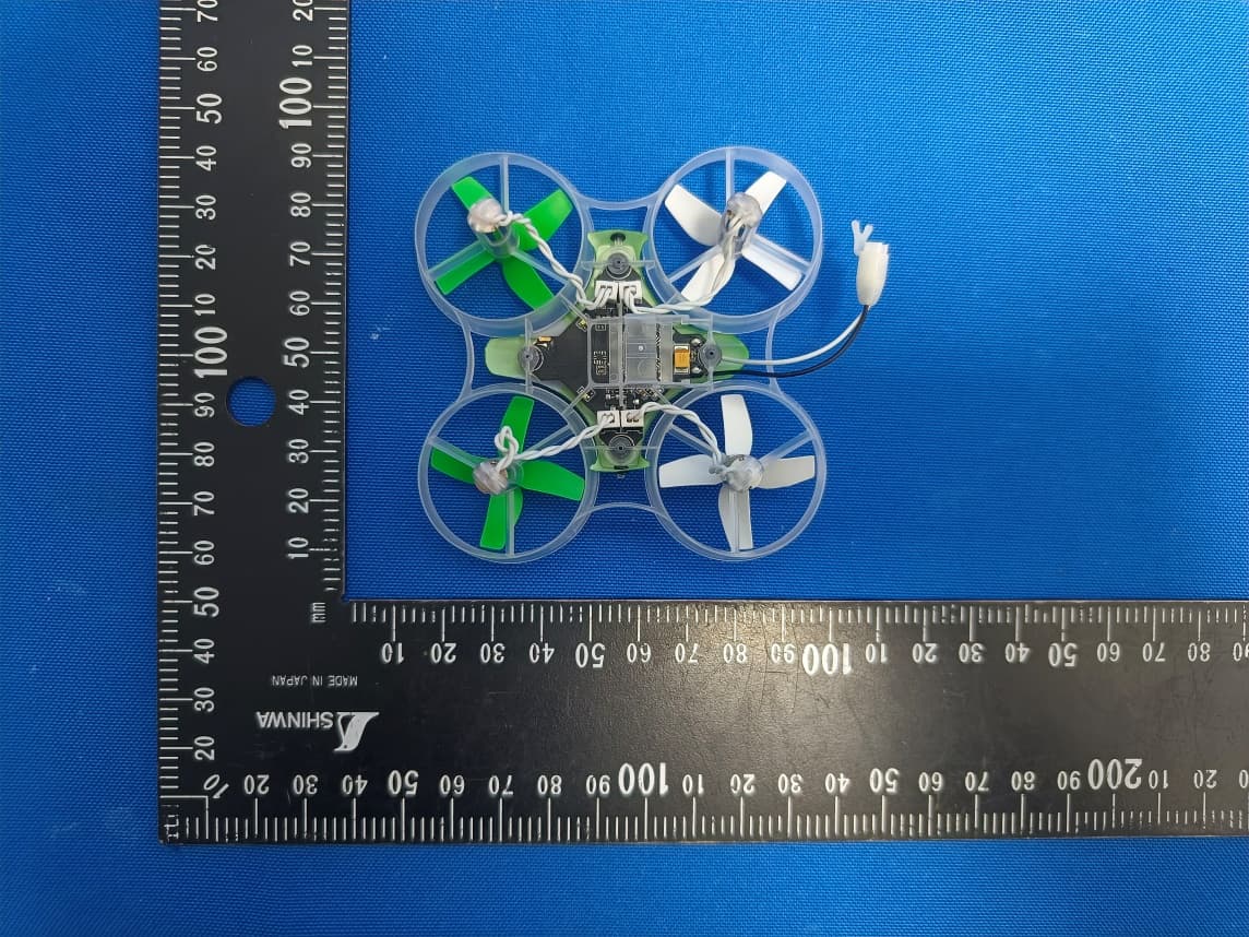
BRWBLH08701
Jul 29, 2023Inductrix RTF
Equipment Class
DTS - Digital Transmission System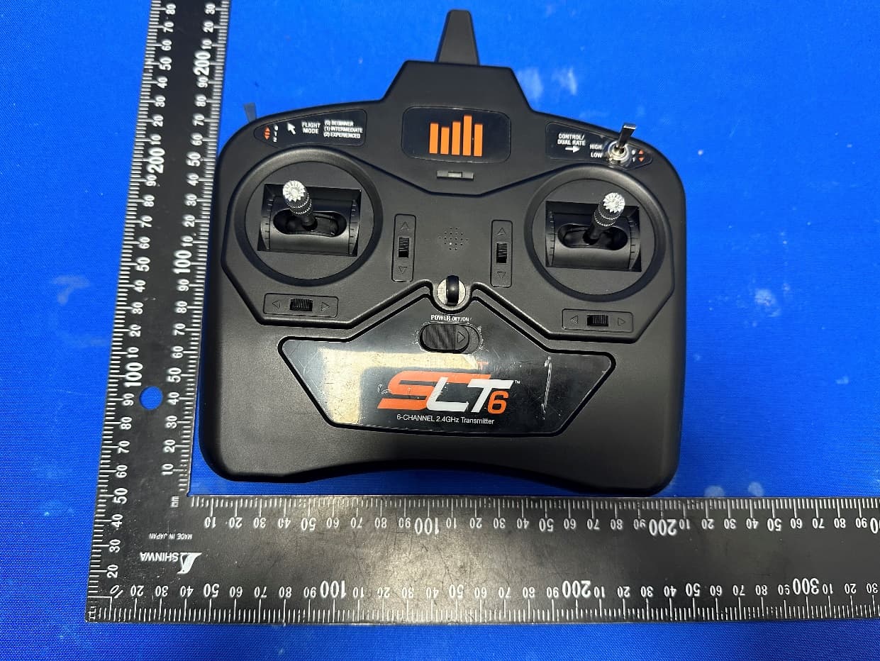
BRWSPMR1275
May 05, 2023SLT6
Equipment Class
DTS - Digital Transmission System
BRWSPMAR10360T
Oct 11, 2020AR10360T 10 Channel AS3X/SAFE Telemetry Receiver
Equipment Class
DSS - Part 15 Spread Spectrum Transmitter
BRWSPMAR10100T
Oct 11, 2020AR10100T 10 Channel Telemetry Receiver
Equipment Class
DSS - Part 15 Spread Spectrum Transmitter
BRWSPMSR6200A
Aug 11, 20206CH AVC surface receiver
Equipment Class
DXX - Part 15 Low Power Communication Device Transmitter