BRWXR3I
Horizon Hobby, LLC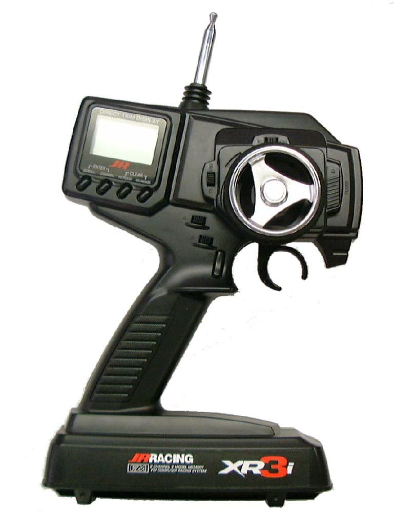
Click to zoom
Application Details
- Equipment Class
- TNB - Licensed Non-Broadcast Station Transmitter
- Date of Grant
- Sep 18, 2002
- Application Purpose
- Original Equipment
- Date of Application
- Aug 07, 2002
- Frequency Range
- 75.41000000 - 75.99000000
- Company
- Horizon Hobby, LLC
- Country
- United States
Documents & Files
Document Text
Text extracted from the exhibit documents filed with the FCC. Open a document above to read the original.
Users Manual
3-Channel, 4-Model Memory FM Computer Racing System 4680 JR XR3i manual 7/17/02 12:14 PM Page 1 2 Model Select . . . . . . . . . . . . . . . . 14 Model Name Entry . . . . . . . . . . . 14 Frame Rate Select . . . . . . . . . . . . 15 Auxiliary Channel 3 Function Select . . . . . . . . . . . . . 16 Grip Button C Function Select 17 Data Reset . . . . . . . . . . . . . . . . . . . 19 Copy Model Data . . . . . . . . . . . . 20 Accessing the Function Mode . . . 21 Throttle Deadband . . . . . . . . . . . . 22 Exponential . . . . . . . . . . . . . . . . . . 23 End-Point Adjustment . . . . . . . . 24 Programmable Mixing . . . . . . . . 26 Lap-Timer . . . . . . . . . . . . . . . . . . . 27 Sub-Trim . . . . . . . . . . . . . . . . . . . 28 Servo Reversing . . . . . . . . . . . . . 29 Accessing the Direct Trim Mode 30 Steering Trim . . . . . . . . . . . . . . . . 31 Throttle Trim . . . . . . . . . . . . . . . . . 32 Grip Lever B: Steering Dual-Rate Trim Adjustment STG . . . . . . . . . 33 Grip Lever A: Brake Endpoint Adjustment BRK . . . . . . . . . . . . . 34 Auxiliary Channel 3 Access . . . . 35 XR3i Data Sheets . . . . . . . . . . . . . . . 36 Frequency Chart . . . . . . . . . . . . . . . 38 Warranty and Service Information 39 Introduction . . . . . . . . . . . . . . . . . . . . . 2 XR3i Quick Start Setup . . . . . . . . . . . 3 Direct Trim Access . . . . . . . . . . . . . . 4 Servo Trim Adjustment . . . . . . . . . 4 System Features . . . . . . . . . . . . . . . . . 5 Transmitter . . . . . . . . . . . . . . . . . . . 5 Receiver . . . . . . . . . . . . . . . . . . . . . . 5 Servos . . . . . . . . . . . . . . . . . . . . . . . 5 System Specifications . . . . . . . . . . . 6 Components . . . . . . . . . . . . . . . . . . 6 Transmitter . . . . . . . . . . . . . . . . . . . 6 Receiver . . . . . . . . . . . . . . . . . . . . . . 6 Servos . . . . . . . . . . . . . . . . . . . . . . . 6 Control Identification and Location . . . . . . . . . . . . . . . . . . . . 7 R/C Safety Precautions . . . . . . . . . . . 8 Steering Tension Adjustment . . . . . 9 Charging Jack . . . . . . . . . . . . . . . . . . 9 Receiver/Servo Connections and Installation . . . . . . . . . . . . . . . . . 10 Operating Your Model . . . . . . . . . . 11 Servo Layout . . . . . . . . . . . . . . . . . . 11 Key Input and Display . . . . . . . . . . . 11 Display Screens . . . . . . . . . . . . . . . . 12 Normal Display . . . . . . . . . . . . . . 12 Up-Timer . . . . . . . . . . . . . . . . . . . _? Low-Battery . . . . . . . . . . . . . . . . . 12 Lithium Battery . . . . . . . . . . . . . . . 12 Memory Backup . . . . . . . . . . . . . 12 Accessing the System Mode . . . . 13 Table of Contents Introduction Thank you for purchasing the XR3i 3-channel radio system. This system has been designed to provide R/C racers with a high quality, user-friendly radio system that can be relied upon year after year, race after race. The XR3i's grip dial accessible auxiliary third channel is ideal for use as a mixture channel in gas boats or as a transmission shifter for vehicles such as the Traxxas ® T-Maxx. It is important that you carefully read this manual before attempting to operate your XR3i system. For your convenience, a blank data sheet has been included in the back of this manual. Once you have input all the necessary data for a particular model into your transmitter, we strongly recommend that you immediately write that information down on the data sheet provided. This will insure that in the rare case of a memory failure, you will not lose the models' setup data. For those who would like to get out to the track quickly with just the basic radio setup, please refer to the Quick Start section that follows. 4680 JR XR3i manual 7/17/02 12:14 PM Page 2 3 Included in this manual are in-depth instructions detailing all the steps and procedures needed to correctly program each of the XR3i's features. Quick Start covers the basic programming information necessary to get you to the track fast. Later, when you want to learn more about the specific features of the XR3i, refer to the appropriate page(s) in this manual for more detailed programming information. Note:If the Auxiliary Channel 3 is required, refer to the Auxiliary Channel 3 System Mode (page 16) for instructions. Servo Reversing 1.With the transmitter power switch on, press the Scrollkey to enter the Function mode. 2.Press the Scrollkey until "REV.NORM" appears on the screen. The "ST" indicates the steering servo reversing screen. 3.Press the Increaseor Decreasekey to move the cursor to the desired servo direction (Rev.Norm). 4.Press the Channelkey once to access the throttle servo reversing screen. 5.To select the direction of the throttle servo, repeat Step 3 above. 6.Repeat Steps 2 and 3 to adjust Auxiliary Channel 3 if needed. End-Point (Travel) Adjustment 1.From the Servo Reverse function, press the Scrollkey three times to access the End-Point (Travel) Adjustment function (the EPA screen with "ST" will appear). Steering Adjustment 2.Rotate the steering wheel in the desired direction (left or right) to be adjusted. 3.Press the Increaseor Decreasekeys to select the desired travel value. Throttle Adjustment 4.Press the Channelkey once. "TH" will appear on the screen. 5.Pull the trigger for foward or push the trigger for brake adjustment. 6.Press the Increaseor Decreasekeys to select the desired travel value. Auxiliary Channel 3 Adjustment If a third channel is not required, proceed to Step 8. 7.Press the Channelkey once. "AUX" will appear on the screen. 8.Press the Increaseor Decreasekeys to select the desired travel value. 9.Press the Scrolland Channelkeys at the same time to exit the function mode. st — REV•NORM SCROLL ENTER CHANNEL CHANNEL CHANNEL SCROLL SCROLL INCREASE CLEAR DECREASE INCREASE CLEAR DECREASE INCREASE CLEAR DECREASE INCREASE CLEAR DECREASE Channel ST = Steering TH = Throttle AUX = Auxiliary Channel 3 (optional) Servo Direction st R/B 100 EPA Adjustment Position ST = Steeri…
Text truncated - open the document above for the full version.
Cover Letter(s)
August 8, 2002 Federal Communications Commission Equipment Authorization Division, Applications Processing Branch 7435 Oakland Mills Road Columbia, MD 21046 RE) FCC ID: BRWXR3i (EA906568) To whom it may concern; Please refer to the additional information listed below while reviewing the BRWXR3i System. 1) Section 95.645 (b) states that plug-in crystals must not be accessible to the user. Indicate whether or not crystals are accessible to the user. Although the transmitter crystal is visible from the back of the transmitter, each crystal is glued in place prior to shipment making it a permanent installation. Consumer removal of the crystal will normally result in damage to the crystal. Therefore, frequency changes are done at the service center only. 2) The Manual must contain warnings per section 95.653 A) Please refer to the manual attachment for this information B) All content for operation is contained in the instruction manual. 1) All instructions are contained in the instruction manual. 2) There are no adjustments accessible to the user that would be in violation with the FCC rules. 3) This section is not applicable to our use. If there is any further information required, please contact me directly at: Horizon Hobby Distributors ATTN: Len Sabato Fax: 217-355-0058 Phone: 217-403-3588 [email protected]
Cover Letter(s)
HORIZON Hobb MEMO 4105 Fieldstone Road, Champaign, IL 61822 From the desk of: Phone: 217-403-3588 Fax: 217-355-0058 Len Sabato Email:[email protected] 1 To:Linda Elliott Subject:BRWXR3I Information From:Len Sabato Date:August 21, 2002 Pages:1 of 1 Ref . #:23738 Conf. #:EA906568 Dear Linda: Thank you for your correspondence of 8/21/02 with regards to the filing of BRWXR3I. My responses to your requests are as follows: 1) Identification Label Photo Noted. According to my records (printed copy of attachments submission form), this information was provided in the original filing. The file was named “XR3i ID Label Location, and it was 42259 bytes. This photo should show the back of the transmitter with the label in place. This information can also be found as page 17 of the Technical Report that was also submitted. Please advise me if you require additional information. 2) External Photographs Noted. This information was also provided in the original filing with the file names; XR3i External Photo Front (54304 bytes) XR3i External Photo Rear (42259 bytes) These photos can also be found on pages 13 and 17 of the Technical report that was also submitted with these exhibits. Since the filing of these all received an “OK” when they were transmitted, I am assuming that these files were able to be opened. If there is an additional problem with these files mentioned above, please advise me by return e-mail ([email protected]), and I will provide you with the documentation need. Thank you for your time Linda. Best Regards; Len Sabato
Cover Letter(s)
HORIZON Hobb MEMO 4105 Fieldstone Road, Champaign, IL 61822 From the desk of: Phone: 217-403-3588 Fax: 217-355-0058 Len Sabato Email:[email protected] 1 To:Linda Elliott Subject:BRWXR3i From:Len Sabato Date:August 22,2002 Pages:1 of 1 Ref. #: 23750 Conf. #:EA906568 Dear Linda; Good Day. Thank you for your communication of 8/22 with regards to the filing of BRWXR3i. I have looked into this situation, and I have found that the files that were sent for the following items were not correct: External Photos Internal Photos ID Label Location Schematics The files that were sent were pages from the instruction manual, which were saved in error, and not correct as you have mentioned. I am including the corrected attachments with this filing. Please accept my apologies for any inconvenience. I believe that these additional exhibits will clarify the situation. Please contact me with any additional questions. Thank you for your time Linda. Best Regards; Len Sabato
External Photos
FCC ID# BRWXR3i page 13
External Photos
page 17 FCC ID# BRWXR3i
ID Label/Location Info
17 The Grip Button C function of the XR3i allows you to select from 3 different functions available. Use the information below to select the correct Grip Button C assignment for your particular installation. "0": Off. (Default) If "AUX " is "2P ", then "2P " replaces"0" in this screen. "Eb": ESB (Emergency Steering Button.) To cancel the "STG" regulation for panic steering. "LA": Lap timer. Note:If "LA" or "Eb" is selected and "2P" is assigned to the Auxiliary Channel 3 function, the Auxiliary Channel 3 function is moved to Grip Dial A. (Factory preset) 00 = The 0, or off function, is the default setting and does not assign a function to Grip Button C. If the Auxiliary Channel 3 function is set to "2P" or 2-position, "2P" will appear in this screen in place of "0" and Grip Button C will function as the gear select button. EEBB = The Eb or Emergency Steering Button function is designed to override the value of Grip Dial B and provide 100% steering rate. This feature is useful if you have re- duced the steering rate to make your vehicle easier to drive but need full steering in an emergency situation such as a collision. {Figure 24-Insert new drawing of Grip Button C and Eb value Callout GBC - Callout Eb - Indicates Emergency Steering Button is activated} LLAA = The LA or Lap-Timer function is designed to be used when you want to enable the recording of individual lap time. The Lap-Timer function is described on page 27. {Figure 24-Insert new drawing of Grip Button C and LA value Callout GBC - Indicates Grip Button C function Callout LA - Indicates Lap Timer button is activated} gbc LA Grip Button Function Lap-Timer gbc 0 Grip Button C Function Grip Button C is Inhibited gbc EB Grip Button C Function Emergency Steering Button is Activated gbc LA Grip Button C Function Lap-Timer Button is Activated Grip Button C Function Select (System Mode) 4680 JR XR3i manual 7/17/02 12:14 PM Page 17
ID Label/Location Info
page 17 FCC ID# BRWXR3i
Internal Photos
FCC ID# BRWXR3i page 14 page 15 FCC ID# BRWXR3i FCC ID# BRWXR3i page 16
Operational Description
Page 1 Technical Report Transmitter Model XR3i FCC ID# BRWXR3i T A B L E O F C O N T E N T S 1.0 INTRODUCTION 1.1 Definition 1.2 Application 1.3 Construction 2.0 ENCODER THEORY OF OPERATION 3.0 THEORY OF OPERATION 3.1 General 3.2 Block Diagram 4.0 FAILURE ANALYSIS 5.0 APPENDICES 5.1 Transmitter Block Diagram 5.2 Transmitter Schematic Diagram 5.3 Transmitter Photographs and ID Labels 5.4 Transmitter Tune-Up Procedure 5.5 Quarts Crystal Specifications 5.6 Test Data Page 2 Technical Report Transmitter Model FCC ID# BRWXR3i 1.0 INTRODUCTION 1.1 Definition The Model XR3i is a transmitter for the Remote Control (R/C) of models such as cars, boats,etc. This Transmitter is for FM System, available for the PPM(Pulse Position Modulation) This Transmitter is a part of the HORIZON HOBBY DISTRIBUTORS, INC. PPM"family" of Remote Control Transmitters which at this time consists of: Transmitter Model # FCC ID # XR-3 BRWXR-3 Separate Applications for each transmitters and for the receivers are submitted as required by the Commission. The Manufacturer, Japan Remote Control Company (JR), manufactures all transmitters and receivers. The PPM family of R/C systems is exported by JR to the United States of America, and several European and Asian Countries. The Applicant for this Equipment Authorization, HORIZON HOBBY DISTRIBUTORS, INC. will, following receipt of Grant of Equipment Authorization, import only those versions of these R/C radios which are allowed for use in the USA under the Rules and Regulations of the Federal Communications. The 75 - 76 MHz version of this transmitter is the subject of this Application; these are the units which will be offered for sale to the general public. Page 3 Technical Report Transmitter Model XR3i FCC ID# BRWXR3i 1.2 Application The Model XR3i R/C transmitter utilizes " Frequency Modulation" to convey the PPM encoded position of its control handle and trigger switches to its companion R/C receiver, where the PPM encoded pulse train is demodulated, decoded, and supplied to a number of servo-mechanisms for positioning of control surfaces, throttle etc. on the model. The Frequency-Shift-Keying of the transmitter carrier takes place in the rhythm of the PPM pulse train. Both transmitter and receiver are very narrow band units; they have been designed to comply with the European requirements of 10 KHz channel spacing. 1.3 Construction The Model XR3i Transmitter all consists of a plastic case. (Reference is made to Fig. 5.1, Transmitter Block Diagram) * control handle and trigger * a 9.6V rechargeable (nicad) battery * an analog-to-digital converter (ADC) * a microprocessor to create the PPM pulse train (M38C24M4) * a modulator driver stage * a RF power stage * a telescopic antenna This Transmitter is to be made available by the importer only on those carrier frequencies in the 75 - 76 MHz frequency band which are at present authorized for R/C use. Page 4 Technical Report Transmitter Model XR3i FCC ID# BRWXR3i 2.0 ENCODER THEORY OF OPERATION Reference is made to Figure 5.1, Transmitter Block Diagram. The functions of the encoder are to: * accept the analog voltages from the control inputs (handle and trigger). * process the analog voltages to create control mixing, adding, reversing, etc., as desired by the user. * sample these voltages in a cyclic rhythm under control of the system's internal timing generator. (This process is called commutation.) * process these analog voltages into binary weighted digital control words by means of an Analog-to-Digital Converter (ADC). * store these digital representations of the analog control input into a temporary memory (RAM). * supply this serial data stream to a buffer-driver for modulation of the RF Transmitter. * provide "housekeeping" of the encoding process by means of a quarts crystal controlled internal clock. * provide supply voltages to the RF section (Vcc = 9.6V battery voltage; Vreg = 6.0V regulated voltage). The entire program which controls the timing housekeeping, parallel-to-serial conversion process, and insertion of synchronization words and error detection codes is governed by a Central Processing Unit (CPU) under control by an internally stored program residing in Read-Only Memory (ROM). The CPU, RAM and ROM are all part of a single-chip microprocessor. Resolution of the Analog-to-Digital conversion process is nine (9) bits for a control accuracy of 1:2 9 Page 5 Technical Report Transmitter Model XR3i FCC ID# BRWXR3i 3.0 THEORY OF OPERATION 3.1 General Reference is made to Figure 5.1, Transmitter Block Diagram. The HORIZON HOBBY DISTRIBUTORS, INC. Model XP662 R/C Transmitter is It operates on any of the R/C frequency (Channels) allowed by the Commission in the 75 -76 MHz frequency band. Selection of the desired RF channel is made by Quarts crystal. This transmitter employs Frequency-Sift-Keying (FSK) of the carrier frequency, whereby the output frequency is either low or high due to the symmetrical FSK modulation process, the (center) output frequency cannot be directly measured, but must be calculated by taking the average of the high and low frequency states. The peak-to-peak deviation of the FSK signal is approximately 3.6 KHz ("sliver modulation") Because of the unfamiliarity of the general public with the term FSK, this modulation technique is commonly named FM. m m m = shift from center frequency m = approx. 1.8 KHz f f f low c high f low + f high f carrier = 2 handle and trigger Transmitter. Page 6 Technical Report Transmitter Model XR3i FCC ID# BRWXR3i 3.2 Block Diagram (Reference is made to Figure 5.1) The (up to) four control potentiometers are at the right side of the schematic drawing. The control potentiometer, which is mechanically coupled to the control handle and trigger, is supplied with the regulated 5.0V voltage. The wiper on this pot is exactly centered in the neutral control stick position. All analog processing is performed as deviations from this center (reference) voltage. After the mixing of e…
Text truncated - open the document above for the full version.
Parts List/Tune Up Info
A-014-02-C Page 1 of 20 KEC Ikoma Testing Laboratory 12128 Takayama-cho Ikoma-city Nara 630-0101 Japan Designated by Ministry of international Trade and industry KANSAI ELECTRONIC INDUSTRY DEVELOPMENT CENTER HEAD OFFICE IKOMA TESTING LABORATORY 6-8-7 NISHITENMA 12128 TAKAYAMA-CHO KITA-KU OSAKA 530-0047 JAPAN IKOMA-CITY NARA 630-0101 JAPAN Corporate Juridical Person TEST REPORT Report No.A-014-02-C Date: 19 July 2002 This test report is to certify that the tested device properly complies with the requirements of: FCC Rules and Regulations Part 95 : Radio Control (R/C) Radio Service. The tests necessary to show compliance to the requirements were performed and these results met the specifications of requirement. The results of this report should not be construed to imply compliance of equipment other than that, which was tested. Unless the laboratory permission, this report should not be copied in part. 1. Applicant Company Name : JAPAN REMOTE CONTROL CO., LTD. Mailing Address : 2-2-12, EIWA, HIGASHIOSAKA-CITY, OSAKA, 577-0809 JAPAN 2. Identification of Tested Device Type of Device : Radio Control (R/C) Radio Service. Kind of Equipment Authorization : : DoC : Certification : Verification FCC ID : BRWXR3i Device Name : FM 3-CHANNEL TRANSMITTER Trade Name : JR PROPO Model Number : XR3i Serial Number : No.1 : Prototype : Pre-production : Production Date of Manufacture : June 2002 3. Test Items and Procedure : RF Power Output (Substitution Method) : Modulation Characteristics : Necessary Bandwidth : Emission Bandwidth : Field Strength of Spurious Radiation : Frequency Stability Measurement Above all tests were performed under: FCC Part 2 Sec2.1046, Sec2..1047, Sec2.1049, Sec2.1053, Sec2.1055 and Sec2.1057. : without deviation, : with deviation (details are found inside of this report) 4. Date of Test Receipt of Test Sample : 14 June 2002 Test Completed on : 10 July 2002 Seiichi Izumi General Manager of Ikoma Testing Laboratory A-014-02-C Page 2 of 20 KEC Ikoma Testing Laboratory 12128 Takayama-cho Ikoma-city Nara 630-0101 Japan Table of Contents 1. GENERAL INFORMATION.................................................................................................. 3 1.1. Product Description.......................................................................................................... 3 1.2. Description for Equipment Authorization ....................................................................... 3 1.3. Test Facility ...................................................................................................................... 3 2. TESTED SYSTEM................................................................................................................. 4 2.1. Test Mode.......................................................................................................................... 4 2.2. Block Diagram of EUT System ........................................................................................ 4 2.3. List of EUT System .......................................................................................................... 5 2.4. List of Antenna ................................................................................................................. 5 3. RF OUTPUT POWER AND RADIATED SPURIOUS EMISSIONS ..................................... 6 3.1. Reference Rule and Specification .................................................................................... 6 3.2. Test Procedure .................................................................................................................. 6 3.3. Test Configuration............................................................................................................ 7 3.4. Photographs of EUT System Configuration .................................................................... 9 3.5. Test Results .....................................................................................................................11 4. MODULATION CHARACTERISTICS................................................................................ 12 4.1. Reference Rule and Specification .................................................................................. 12 4.2. Test Results .................................................................................................................... 12 5. EMISSION BANDWIDTH .................................................................................................. 13 5.1. Reference Rule and Specification .................................................................................. 13 5.2. Test Configuration.......................................................................................................... 13 5.3. Test Results .................................................................................................................... 14 6. FREQUENCY STABILITY MEASUREMENT ................................................................... 18 6.1. Reference Rule and Specification .................................................................................. 18 6.2. Frequency vs Temperature Test..................................................................................... 18 6.3. Frequency vs Voltage Test.............................................................................................. 19 7. USED TEST EQUIPMENTS AND CALIBRATION STATUS ............................................ 20 A-014-02-C Page 3 of 20 KEC Ikoma Testing Laboratory 12128 Takayama-cho Ikoma-city Nara 630-0101 Japan 1. GENERAL INFORMATION 1.1. Product Description The JR PROPO Model No. XR3i (referred to as EUT in this report) is the FM 3 – CHANNEL TRANSMITTER. (1) Transmitting Frequency : 75.41 ∼ 75.99 MHz (75.650 MHz in EUT) (2) Contained Oscillator : 4th OVER-TONE (3) Rated Power Supply : DC 9.6 V (Ni-cd battery × 8) 1.2. Description for Equipment Authorization (1) Rules Part (s) under which Equipment operated FCC Rule Part 95 ; Radio C…
Text truncated - open the document above for the full version.
Schematics
Xtal ANT mp. PowerAmp. BandPass Filter Modulator Regulator A CN2C 10C CN3C 13C12C 12B 13 13B 12 24J237-2 8C 9C 7C 28 2726 25B 24B23B22B 21B 20B 25 24 23 2221 20 19C 18C 17C 19B 18B 17B 19 Xtal TypeRF PCB 24J237 24J237-1-2 24J237-4 24J237-3 2CH 1CH 18 17 16 15 14 CN6 CN5B CN5 CN4B CN4 11B 11 9 MODGNDVcc 87 CN3B CN3 CN2 LOW HIGH RIGHT LEFT TH.TRIM ST.TRIM EDIT KEY MOD CH DEC INC Grip C Grip B (L) Grip A (R) Grip B (R) Grip A (L) RESET 42 41 39 38 X1 X'tal 6.8270MHz CH22P C40 CH18P C41 5v C43 103 1K *R43*R42 1K R44 1K R45 1K 123 JACK 1 JC_HEC0749 BZ CB13PA-X R21 1K 1K R28 D4 1S1885 DTC114EK Q2 Vcc Vcc 102 C23 10K R15 5K 1K R49 1K R50 R1 2.2K 103 C3 R2 4.7K R5 10K C2103 47u16V C4 C1 100u25V R3 7.5K C8 103 C9 102 Litium 3V BATT. 5v D1 1SS352 Q1 2SC3265Y D2 1SS352 Vcc IC2 78L05F C6 47u16V IC3 RH5VA40AA R7 1K R11 1K R12 1K R13 1K R14 1K 1 2 S6 1 2 S7 1 2 S8 1 2 S9 56K R29 36K R30 Vcc *R39 *R38 1K *R40 1K R37 5K 1 2 S14 1 2 S13 1 2 S12 1 2 S11 1K R48 1K R47 1K R46 1 2 S10 103 C39 2.2K R32 10K R20 *R41 Q4 2SA1204Y R22 10K C35 103 R23 1K C26 103 C27 47u16V *R35 *R36 5v SEG.15 SEG.14 SEG.13 SEG.12 SEG.11 SEG.10 SEG. 9 SEG. 8 SEG. 7 SEG. 6 SEG. 5 SEG. 4 SEG. 3 SEG. 2 SEG. 1 SEG. 0 COM. 3 COM. 2 COM. 1 COM. 0 L C D GS-30803-TRPC 1 2 3 4 5 6 7 8 9 10 11 12 13 14 15 16 17 18 19 20 5v C44 102 C45 103 C42 102 5v C52 103 1 2 S2 1 2 S3 1 2 S4 1 2 S5 2.2K R16 C37 103 123 456 S1 C28 103 C31 103 102 C47C48 C49C50C51 R31 10K C38 104 R4 1K C7 102 1K R8 1K R9 1K R10 DTC114EK Q3 2.2K R17 103 C5 5v Q5 DTC114EK C29 103 R34 10K ANT BATT.10V JPC2 JPW R57 10K 5v RTP0P47/RTP1 RESET XIN XOUT Vss AVSSVREF P40/AN0 P42/AN2 P41/AN1 P43/AN3 P44/AN4 P45/AN5 VLC3COM3COM1COM2COM0 P20/SEG16 M38C24M4-XXXFP P17/SEG15 P15/SEG13 P16/SEG14 P10/SEG8 P11/SEG9 P12/SEG10 P13/SEG11 P14/SEG12 IC-1 CNVss P62/XCOUT P61/XCIN Vcc P60/CNTR1 P37/CNTR0 P36 P31/SCLK2 P32/TXD2P33/RXD2 P34P35 P30/SRDY2 P27/SEG23P26/SEG22P25/SEG21 SEG20 P21/SEG17 SEG18 SEG19 P57/SRDY1P56/SCLK1P55/TXD1P54P53/PWM1 P52P51 P50/INT0 P07 P04 P05 P06 P03 P00 P01 P02 P24 P23 P46 P22 1 2 3 4 5 6 7 8 9 10 11 12 13 14 15 16 17181920212223242526272829303132 33 34 35 36 37 39 39 40 41 42 43 44 45 46 47 48 49505152535455565758596061626364 R58 10K 103 C53 103 C54 C55 103 C56 103 C57 103 R59 100K Sold.JP JP2 D6 1SS352 JPC1 FCC ID# BRWXR3i Figure 5.2.1. Transmitter Schematic Diagram Page 10 ( 10turn ) ( 8turn ) 10C 9C 4P-SAN board in ANT. 8C 7C CN2C MOD GND Vcc Vcc 6V Q205 2SC2859Y R222 560 1SV231 D202 X201 20PF VC201 R221 10K R219 10K R220 12K R223 33 22K R225 3.3K R226 Q207 2SC4269(3,4) R227 33 R228 10 R230 150 R232 5.6 R231 3.3K Q208 2SC2988 R235 6.8 R234 6.8 R236 330 C254CH18P C253 CH82P C256 CH120P C259 CH39P C250 102 C249 102 CH68p C246 3P C244 C260 CH3P 220P C227 220P C228 8P C226 56P C237 47P C231 102 C239 R2413.3K P201 1K R242 820 R243 330 Q209 2SC2712GR R244 100 R246 8.2K R248 4.7K R247 22K Q210 2SC2712GR C272 102 R249 10K 103 C251 103 C247 C268 B472 C269 B182 C234 103 B470p C271 3.3uH L207 103 C230 TW-72S L203 10 R224 R233 6.8 02DZ6.8Y D203 2SC3265YQ201 103 C265 103 C267 680 R237 103 C263 C274 CH220P C275 CH220P L201 TW-72S 12P C243 CH5P C240 102 C241 C273 103 Vcc L205F72C C235 103 L202 TW-72S C257 JPW L206 F3544C 53LSS L204 CH2p C248 FCC ID# BRWXR3i Figure 5.2.2. Transmitter Schematic Diagram Page 11
Test Report
A-014-02-C Page 1 of 20 KEC Ikoma Testing Laboratory 12128 Takayama-cho Ikoma-city Nara 630-0101 Japan Designated by Ministry of international Trade and industry KANSAI ELECTRONIC INDUSTRY DEVELOPMENT CENTER HEAD OFFICE IKOMA TESTING LABORATORY 6-8-7 NISHITENMA 12128 TAKAYAMA-CHO KITA-KU OSAKA 530-0047 JAPAN IKOMA-CITY NARA 630-0101 JAPAN Corporate Juridical Person TEST REPORT Report No.A-014-02-C Date: 19 July 2002 This test report is to certify that the tested device properly complies with the requirements of: FCC Rules and Regulations Part 95 : Radio Control (R/C) Radio Service. The tests necessary to show compliance to the requirements were performed and these results met the specifications of requirement. The results of this report should not be construed to imply compliance of equipment other than that, which was tested. Unless the laboratory permission, this report should not be copied in part. 1. Applicant Company Name : JAPAN REMOTE CONTROL CO., LTD. Mailing Address : 2-2-12, EIWA, HIGASHIOSAKA-CITY, OSAKA, 577-0809 JAPAN 2. Identification of Tested Device Type of Device : Radio Control (R/C) Radio Service. Kind of Equipment Authorization : : DoC : Certification : Verification FCC ID : BRWXR3i Device Name : FM 3-CHANNEL TRANSMITTER Trade Name : JR PROPO Model Number : XR3i Serial Number : No.1 : Prototype : Pre-production : Production Date of Manufacture : June 2002 3. Test Items and Procedure : RF Power Output (Substitution Method) : Modulation Characteristics : Necessary Bandwidth : Emission Bandwidth : Field Strength of Spurious Radiation : Frequency Stability Measurement Above all tests were performed under: FCC Part 2 Sec2.1046, Sec2..1047, Sec2.1049, Sec2.1053, Sec2.1055 and Sec2.1057. : without deviation, : with deviation (details are found inside of this report) 4. Date of Test Receipt of Test Sample : 14 June 2002 Test Completed on : 10 July 2002 Seiichi Izumi General Manager of Ikoma Testing Laboratory A-014-02-C Page 2 of 20 KEC Ikoma Testing Laboratory 12128 Takayama-cho Ikoma-city Nara 630-0101 Japan Table of Contents 1. GENERAL INFORMATION.................................................................................................. 3 1.1. Product Description.......................................................................................................... 3 1.2. Description for Equipment Authorization ....................................................................... 3 1.3. Test Facility ...................................................................................................................... 3 2. TESTED SYSTEM................................................................................................................. 4 2.1. Test Mode..................................................................…
Text truncated - open the document above for the full version.
Contact Information
Applicant
Jason Rosa(Lead Quality and Compliance Associate)
Test Firm
Kansai Electronic Industry Dev. Ct.Eizo Hariya
Technical Specifications
| # | Rule Parts | Frequency Range | Power Output | Emission | Tolerance |
|---|---|---|---|---|---|
| 1 | 95C | 75.41 MHz - 75.99 MHz | 79.98 mW | 800KF1D | 0.0020000000 % |
Other Applications from Horizon Hobby, LLC
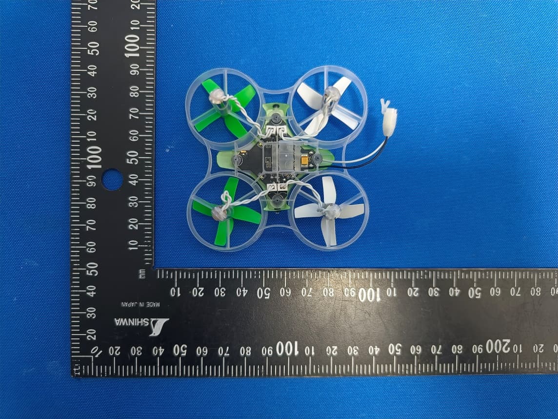
BRWBLH08701
Jul 29, 2023Inductrix RTF
Equipment Class
DTS - Digital Transmission System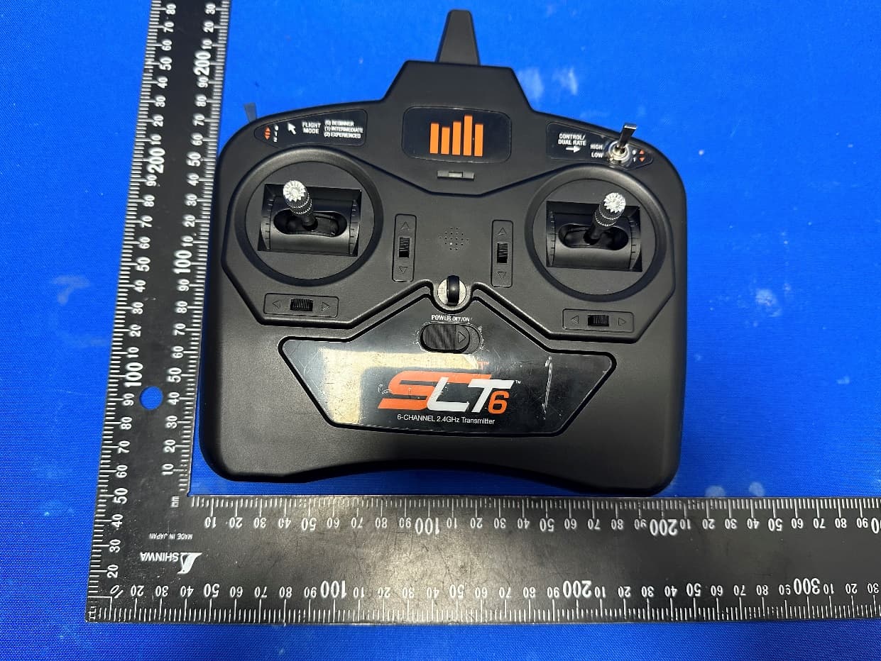
BRWSPMR1275
May 05, 2023SLT6
Equipment Class
DTS - Digital Transmission System
BRWSPMAR10360T
Oct 11, 2020AR10360T 10 Channel AS3X/SAFE Telemetry Receiver
Equipment Class
DSS - Part 15 Spread Spectrum Transmitter
BRWSPMAR10100T
Oct 11, 2020AR10100T 10 Channel Telemetry Receiver
Equipment Class
DSS - Part 15 Spread Spectrum Transmitter
BRWSPMSR6200A
Aug 11, 20206CH AVC surface receiver
Equipment Class
DXX - Part 15 Low Power Communication Device Transmitter