BXZBS330BS330 - UPCS Base Station
Ascom (Sweden) AB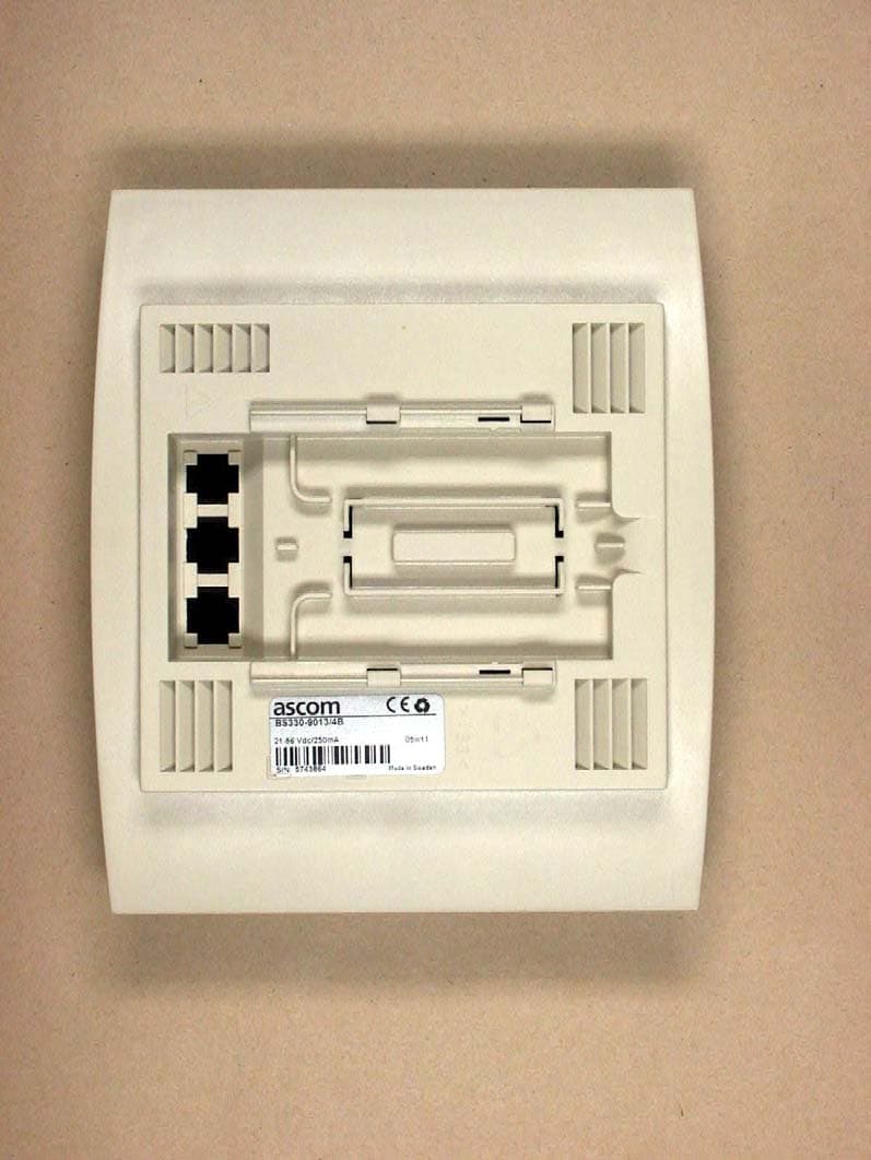
Click to zoom
Application Details
- Equipment Class
- PUB - Part 15 Unlicensed PCS Base Station
- Date of Grant
- Dec 01, 2005
- Application Purpose
- Original Equipment
- Date of Application
- Oct 27, 2005
- Equipment Note
- BS330 - UPCS Base Station
- Frequency Range
- 1921.54000000 - 1928.45000000
- Company
- Ascom (Sweden) AB
- Country
- Sweden
Documents & Files
Document Text
Text extracted from the exhibit documents filed with the FCC. Open a document above to read the original.
Users Manual
Installation instructions, BS330 base station Technical Product Manual - DCT1800-GAP TD 92093 (1/LZBNB 103 108 R4D) / 2005-09-23/ Ver.C 2005 63 Chapter 16 BS330 base station 16.1General The base station is connected to the radio exchange by means of a standard twisted pair cable. The base station is can be fixed to a wall, a ceiling, a pole or a beam, by means of the mounting bracket included. When fixing the base station to a wall or ceiling the included plugs and screws must be used. When fixing it to a pole or beam a (not included) strap a flexible metal band must be used. Versions The following versions of the BS330 are available: •BS330/STD: 1880 – 1900 MHz •BS330/CHINA: 1900 – 1920 MHz •BS330/LA: 1910 – 1930 MHz •BS330/US&CDA: 1920 – 1930 MHz Contents of the box The box in which the base station is packed contains: •A base station •A mounting bracket •Two screws with wall plugs Note: The brand label is not included in the box, but must be ordered separately. Power distribution Base stations can be powered by the following sources: •The radio exchange via the data pairs •The radio exchange via the data and Express Powering Pairs (EPP) •A 48 V external supply connected to the radio exchange •A local AC-adapter Note: For more information about power distribution, refer to the section ‘Configuration directions’. AC-adapter for a base station A 24 Vdc adapter (BMLNB 101 09/n) can be used. This adapter is provided with an 8-pin RJ45 plug that can be plugged into one of the data/power connectors of the base station. Software If necessary, the software in the base station can be updated by downloading new software to the base station. Downloading can be performed without disconnecting the base stations. The new software is stored in flash memory. How to download the software is described in the help file of the application Cordless System Manager (CSM) for Windows. Installation instructions, BS330 base station Technical Product Manual - DCT1800-GAP TD 92093 (1/LZBNB 103 108 R4D) / 2005-09-23/ Ver.C 2005 64 Connectors •Two 8-pin RJ45 modular jacks for data and powering •A 6-pin RJ12 modular jack for factory testing The two data/powering connectors are interconnected on the board. LEDs LED 1: Green power LED LED 2: Three colour LED, see table 1 Fig. 35 BS330 base station Status of LED2Meaning OffBase station operational and no traffic on the base station GreenBase station operational and traffic on the base station RedBase station is malfunctioning AmberBase station is OK, but not available (self-test, not initialized, no communication with radio exchange) Flashing greenAll 8 channels are in use Flashing amberSoftware is being downloaded to the base station Table 1 Meaning of LED2 Factory testing (RJ12) Data/ power (RJ45) Data/ power (RJ45) Front viewBack view LED1 LED2 037 Installation instructions, BS330 base station Technical Product Manual - DCT1800-GAP TD 92093 (1/LZBNB 103 108 R4D) / 2005-09-23/ Ver.C 2005 65 16.2Base station cabling The base station cable must be a twisted pair cable with 2 pairs minimum for connection of the data lines. Also power can be distributed via these data pairs. A three-pair cable may be used when additional power wires (EPP) are required to increase the distance between base station and radio exchange. If more EPP wires are necessary they can be connected to the EPP pins of the second data/power connector, or they can be connected to one connector when using a screw-to-RJ45 adapter. Data lines of the same twisted pair may be interchanged. For instance SC0-a and SC0-b (see figure 40) may be interchanged. Also the EPP pair is insensitive for polarity reversal. Data pairs may not be interchanged. It is assumed that service personnel know how to crimp these connectors to a cable. Do not power the base station via the EPP terminals from a local power source and the radio exchange simultaneously. As the two EPP inputs of the base station are interconnected in the base station, the two power sources would be interconnected (see figure 36). However, the base station can be powered via the data pairs from the radio exchange and the local power source simultaneously because they are interconnected via a rectifier. Fig. 36 Base station powering 16.3Installation Base stations can be mounted vertically or horizontally. Mount the base stations at places and positions as determined in the system configuration plan. The base station must be placed such that it is not facing large metal objects such as large heating pipes. SC0-b SC1-b SC0-a SC1-a EPP-b EPP-a SC0-b SC1-b SC0-a SC1-a EPP-b EPP-a Data/power connector 1 Data/power connector 2 + − DC DC Base station 038 Installation instructions, BS330 base station Technical Product Manual - DCT1800-GAP TD 92093 (1/LZBNB 103 108 R4D) / 2005-09-23/ Ver.C 2005 66 16.3.1Fixing the mounting bracket to a wall Fix the mounting bracket (see figure 37) to the wall as follows: 1.Hold the mounting bracket with its flat side against the wall such that the text ‘TOP’ is the right way up, and mark the two holes. The minimum distance between the upper hole and the ceiling or any object above the base station must be at least 65 mm (see figure 37). If the distance is less than 65 mm, the base station cannot be slid onto the bracket. 2.When using wall plugs, take a ∅ 6 mm drill and drill the two holes and insert the included wall plugs. 3.Position the mounting bracket with its flat side to the wall and fasten it with the two included ∅ 3.5 mm screws. Fig. 37 Fixing the mounting bracket to a wall TOP ≥ 65 mm Ceiling 039 Installation instructions, BS330 base station Technical Product Manual - DCT1800-GAP TD 92093 (1/LZBNB 103 108 R4D) / 2005-09-23/ Ver.C 2005 67 16.3.2Fixing the mounting bracket to a ceiling Fixing to a ceiling is done in the same way as the a wall (see paragraph 16.3.1). When the base station has to be positioned above a suspended ceiling, take care that the front of the base station points downwards. 16.3.3Fixing the …
Text truncated - open the document above for the full version.
Users Manual
Safety and regulatory information Technical Product Manual - DCT1800-GAP TD 92093 (1/LZBNB 103 108 R4D) / 2005-11-07/ Ver.C © 2005 Safety and regulatory information Section 1 Safety and regulatory information Technical Product Manual - DCT1800-GAP TD 92093 (1/LZBNB 103 108 R4D) / 2005-11-07/ Ver.C © 2005 Safety and regulatory information, Table of contents Technical Product Manual - DCT1800-GAP Table of contents Page TD 92093 (1/LZBNB 103 108 R4D) / 2005-11-07/ Ver.C © 2005 III Chapter 1Introduction .................................................................................................. 1 Chapter 2Safety ............................................................................................................. 3 2.1Safety rules......................................................................................................................................... 3 2.2Safety symbols ................................................................................................................................... 4 2.3Lithium battery on CPU board ........................................................................................................... 4 Chapter 3Protection against electrostatic discharge (ESD) ...................................... 7 3.1General ............................................................................................................................................... 7 3.2ESD handling ..................................................................................................................................... 7 Chapter 4Safety aspects of the DCT1800-GAP system ............................................. 9 Chapter 5Legal restrictions for the Line Termination Unit, LTU – REX-BRD0019 11 5.1Line Termination Unit, LTU – REX-BRD0019 (ROFNB 157 25/2) .............................................. 11 5.2Legal restriction when directly connecting to PSTN ....................................................................... 11 5.2.1Legal restriction for EC and EFTA countries .................................................................................. 11 Chapter 6Standards and Regulations for US ........................................................... 13 6.1Standards and Regulations ............................................................................................................... 13 6.2Radio Equipment: Handsets and Base Stations ............................................................................... 13 6.3Fixed Position System Equipment: Radio Exchange Cabinet and Power Adapters ................................................................................................................................ 13 6.4Regulatory Compliance Statements ................................................................................................. 14 Chapter 7CE-marking ................................................................................................ 17 7.1General ............................................................................................................................................. 17 7.2CE-marking radio exchange.............................................................................................................17 Safety and regulatory information, Table of contents Technical Product Manual - DCT1800-GAP TD 92093 (1/LZBNB 103 108 R4D) / 2005-11-07/ Ver.C © 2005 IV Safety and regulatory information, Introduction Technical Product Manual - DCT1800-GAP TD 92093GB (1/LZBNB 103 108 R4D) / 2005-11-07/ Ver.C © 2005 1 Chapter 1Introduction This section contains important safety and regulatory information. Other sections refer to this section when applicable. Chapter 1:Introduction Introduces you to this document Chapter 2:Safety Informs you about the precautions to take during installation of the DCT1800-GAP system, the lithium battery on the CPU board and the use of the cordless phone. Chapter 3:Protection against electrostatic discharge Informs you about the precautions to take to avoid damage to electrostatic discharge sensitive products and components. Chapter 4:‘Safety aspects of the DCT1800-GAP system’ Lists the safety standards and characteristics that are met by the DCT1800-GAP system. Chapter 6:Regulatory information Informs you about country dependent installation restrictions for the DCT1800-GAP system. Chapter 7:CE marking Informs you about which products comply with European Council Directives. Safety and regulatory information, Introduction Technical Product Manual - DCT1800-GAP TD 92093GB (1/LZBNB 103 108 R4D) / 2005-11-07/ Ver.C © 2005 2 Safety and regulatory information, Safety Technical Product Manual - DCT1800-GAP TD 92093GB (1/LZBNB 103 108 R4D) / 2005-11-07/ Ver.C © 2005 3 Chapter 2Safety 2.1Safety rules •Ensure that the voltage and frequency of the mains power socket matches the voltage and frequency inscribed on the equipment’s electrical rating label. •Never install telephone wiring during a thunderstorm. •Never install telephone jacks in wet locations unless the jack is specifically designed for wet locations. •Never touch un-insulated telephone wires or terminals unless the telephone line has been disconnected at the network interface. Note: Avoid touching or punching down the Base Station signal and power pairs as there is -48Vdc present on these wires at all times. •Use caution and observe all relevant safety standards when installing or modifying telephone lines. •Always install conform relevant national installation rules. •Only mount the radio exchange to a wall. •Do not mount the modular cabinet to a drywall using insertable plastic drywall plugs. These will not safely support the cabinet. See Installation section for recommended mounting. •Suitable for mounting on concrete or other non-combustible surface only. [This refers to the floor covering/ material beneath the cabinet(s)]. •Disconnect all power sources before servicing equipment. •Make sure tha…
Text truncated - open the document above for the full version.
Attestation Statements
SECTION 15.307(b) AFFIDAVIT , Michael Stima. Managing Director of UTAM, Inc.. hereby swear and affirm that: ASGaM WIRELESS SOLUTIONS. [NG. is a participating member of UT AM, Inc. in good standing for purposes of Section 15.307(b) of the FCC rules. Subscribed to and sworn this 30th day of August, 2005 I fl Michael Stima, Managing Director UTAM, Inc. 1170 U.S. Hwy 22 P.O. Box 8126 Bridgewater, New Jersey 08807 Tel: (508) 526-3636 Affidavit #: ASCOO92005
Cover Letter(s)
29th September, 2005 Federal Communications Commission Equipment Authorization Branch 7435 Oakland Mills Road Columbia, MD 21046 Request for Confidentiality Ascom Tateco AB FCC Registration Number (FRN): 0013904214 FCC ID: BXZBS330 FCC Part 15 Certification In accordance with 0.459 of CFR 47, Ascom Tateco AB hereby requests confidentiality of all: Block diagrams . . h Schematics I Parts List - -- 1 attachments for the subject application. These documents contain detailed system and equipment description and related information about the product which Ascom Tateco AB considers to be proprietary, confidential and a custom design and otherwise would not release to the general public. Since the design is a basis from which future technological products will evolve, ~scom-~ateco AB considersthat this information would be of benefit to its competitors and that the disclosure of the information in these documents would give competitors an unfair advantage in the market. Sincerely, Signature Name Title Company Approval & Certijication Engineer Ascom Tateco AB Ascom, Wireless Solutions PO Box 8783, SE402 76 Gothenburg, Sweden T +46 3 1 55 93 00, F +46 3 1 55 20 3 1 www.ascom.com/ws Org.nr./F-skatt 556336-6292, VAT No. SE556336629201, REG. Office: G6TEBORG
External Photos
ELECTRONIC TECHNOLOGY SYSTEMS DR.GENZ GMBH ETS Dr. Genz GmbH, Germany Registration number: G0M20506-9603-C-1 Page 1 of 9 Appendix A. Pictures ELECTRONIC TECHNOLOGY SYSTEMS DR.GENZ GMBH ETS Dr. Genz GmbH, Germany Registration number: G0M20506-9603-C-1 Page 2 of 9
Internal Photos
ELECTRONIC TECHNOLOGY SYSTEMS DR.GENZ GMBH ETS Dr. Genz GmbH, Germany Registration number: G0M20506-9603-C-1 Page 3 of 9 ELECTRONIC TECHNOLOGY SYSTEMS DR.GENZ GMBH ETS Dr. Genz GmbH, Germany Registration number: G0M20506-9603-C-1 Page 4 of 9 ELECTRONIC TECHNOLOGY SYSTEMS DR.GENZ GMBH ETS Dr. Genz GmbH, Germany Registration number: G0M20506-9603-C-1 Page 5 of 9
RF Exposure Info
ETS Dr. Genz GmbH, Germany Registration number: G0M20506-9603-C-1 Page 36 of 59 ELECTRONIC TECHNOLOGY SYSTEMS DR.GENZ GMBH 3.10 Directional gain of the antenna, FCC 15.319 (e) Directional gain of antennas influences the limit of peak transmit power if the maximum directional gain exceeds 3 dBi. Max antenna gain [dBi] Exceeds 3 dBi by amount [dB] 6 3 The antenna gain value is derived from: Manufacturer declaration Antenna diagram Measured gain of complete system Comment: Manufacturer declaration documents or Antenna diagrams will be considered in course of certification by responsible authority. ETS Dr. Genz GmbH, Germany Registration number: G0M20506-9603-C-1 Page 38 of 59 ELECTRONIC TECHNOLOGY SYSTEMS DR.GENZ GMBH 3.12 Radio frequency radiation exposure; FCC 15.319(i) Consideration of radio frequency radiation exposure for EUT is done as SAR test acc. IEEE 1528 MPE calculation as below SAR test results: not applicable MPE calculation: Please find radiated power test results in Appendix J. The EUT is considered as a mobile device according to OET Bulletin 65, Edition – 97 – 01. Therefore distance to human body of min. 20 cm is determined. The limit of Power density for General Population / Uncontrolled Exposure is 1.0 mW/cm 2 . Formula: S = EIRP / 4πR 2 Calculation: EIRP Radiated Power [dBm] 18.87 EIRP Radiated Power [mW] 77.1 R Distance [cm] 20 S Power Density [mW/cm 2 ] 0.015 Result: The EUT complies with the radio frequency radiation exposure requirement. Comment: For radiated power test results see Appendix J.
Test Report
ELECTRONIC TECHNOLOGY SYSTEMS DR. GENZ GMBH TEST - REPORT FCC PART 15 for Isochronous UPCS devices FCC ID: BXZBS330 Test report no.: G0M20506-9603-C-1 Certificate 1983-01 ELECTRONIC TECHNOLOGY SYSTEMS STORKOWER STRASSE 38C, D-15526 REICHENWALDE B. BERLIN DR. GENZ GMBH PHONE +49-33631-888 00 FAX +49-33631-888 66 ETS Dr. Genz GmbH, Germany Registration number: G0M20506-9603-C-1 Page 1 of 59 ELECTRONIC TECHNOLOGY SYSTEMS DR.GENZ GMBH TABLE OF CONTENTS 1 General information 1.1 Notes 1.2 Testing laboratory 1.3 Details of approval holder 1.4 Application details 1.5 Test item 1.6 Test standards 2 TECHNICAL TEST 2.1 Summary of test results 2.2 Test environment 2.3 Test equipment utilized 2.4 Examinations and Test Procedures 2.4.1 Coordination with fixed microwave service, FCC 15.307 (b) 2.4.2 Reference to Subpart B, FCC 15.309 (b) 2.4.3 Labeling requirements, FCC 15.311,15.19(a)(3) 2.4.4 Conducted limits AC Power line, FCC 15.315 , 15.207 2.4.5 Antenna requirement, FCC 15.317, 15.203 2.4.6 Modulation techniques, FCC 15.319 (b) 2.4.7 Emission band width, FCC 15.323 (a); FCC 15.31 (e) 2.4.8 Peak Transmit Power, FCC 15.319 (c) 2.4.9 Power spectral density, FCC 15.319 (d) 2.4.10 Directional gain of the antenna, FCC 15.319 (e) 2.4.11 Automatic discontinuation of transmission, FCC 15.319 (f) 2.4.12 Radio frequency radiation exposure, FCC 15.319 (i) 2.4.13 Monitoring threshold; Least interfered channel; FCC 15.323 (c)(2); (c)(5) (c)(9) 2.4.14 Monitoring of intended transmit window and maximum reaction time, FCC 15.323 (c)(1) 2.4.15 Monitoring band width, FCC 15.323 (c)(7) 2.4.16 Random waiting interval, FCC 15.323 (c)(6) 2.4.17 Duration of transmission, FCC 15.323 (c)(3) 2.4.18 Connection acknowledgement, Unacknowledged transmissions, FCC 15.323 (c)(4) 2.4.19 Selected channel confirmation, Segment occupancy; FCC 15.323 (c)(5) 2.4.20 Monitoring antenna, FCC 15.323 (c)(8) 2.4.21 Duplex connections, FCC 15.323 (c)(10) 2.4.22 Alternative monitoring interval for co-located devices, FCC 15.323 (c)(11) 2.4.23 Fair access to spectrum related to (c)(10) and (c)(11), FCC 15.323 (c)(12) 2.4.24 Emissions inside and outside the sub-band, FCC 15.323 (d) 2.4.25 Frame period, FCC 323 (e) 2.4.26 Frequency stability, FCC 323 (f) ETS Dr. Genz GmbH, Germany Registration number: G0M20506-9603-C-1 Page 2 of 59 ELECTRONIC TECHNOLOGY SYSTEMS DR.GENZ GMBH 3 RESULTS OF EXAMINATIONS AND TESTS 3.1 Coordination with fixed microwave service, FCC 15.307 (b) 3.2 Reference to Subpart B, FCC 15.309 (b) 3.3 Labeling requirements, FCC 15.311, 15.19(a)(3) 3.4 Conducted limits AC Power line, FCC 15.315 , 15.207 3.5 Antenna requirement, FCC 15.317, 15.203 3.6 Modulation techniques, FCC 15.319 (b) 3.7 Emission band width, FCC 15.323 (a) 3.8 Peak Transmit Power, FCC 15.319 (c); FCC 15.31 (e) 3.9 Power spectral density, FCC 15.319 (d) 3.10 Directional gain of the antenna, FCC 15.319 (e) 3.11 Automatic discontinuation of transmission, FCC 15.319 (f) 3.12 Radio frequency radiation exposure, FCC 15.319 (i) 3.13 Monitoring threshold , FCC 15.323 (c)(2); (c)(9) 3.14 Monitoring of intended transmit window and maximum reaction time, FCC 15.323 (c)(1) 3.15 Monitoring band width, FCC 15.323 (c)(7) 3.16 Random waiting interval, FCC 15.323 (c)(6) 3.17 Duration of transmission, FCC 15.323 (c)(3) 3.18 Connection acknowledgement, Unacknowledged transmissions FCC 15.323 (c)(4) 3.19 Selected channel confirmation, Power accuracy, Segment occupancy; FCC 15.323 (c)(5) 3.20 Monitoring antenna, FCC 15.323 (c)(8) 3.21 Duplex connections, FCC 15.323 (c)(10) 3.22 Alternative monitoring interval for co-located devices, FCC 15.323 (c)(11) 3.23 Fair access to spectrum related to (c)(10) and (c)(11), FCC 15.323 (c)(12) 3.24 Emissions inside and outside the sub-band, FCC 15.323 (d) 3.25 Frame period, FCC 323 (e) 3.26 Frequency stability, FCC 323 (f) ETS Dr. Genz GmbH, Germany Registration number: G0M20506-9603-C-1 Page 3 of 59 ELECTRONIC TECHNOLOGY SYSTEMS DR.GENZ GMBH 1 General Information 1.1 Notes The purpose of conformity testing is to increase the probability of adherence to the essential requirements or conformity specifications, as appropriate. The complexity of the technical specifications, however, means that full and thorough testing is impractical for both technical and economic reasons. Furthermore, there is no guarantee that a test sample which has Passed all the relevant tests conforms to a specification. Neither is there any guarantee that such a test sample will interoperate with other genuinely open systems. The existence of the tests nevertheless provides the confidence that the test sample possesses the qualities as maintained and that is performance generally conforms to representative cases of communications equipment. The test results of this test report relate exclusively to the item tested as specified in 1.5. The test report may only be reproduced or published in full. Reproduction or publication of extracts from the report requires the prior written approval of the ELECTRONIC TECHNOLOGY SYSTEMS DR. GENZ GMBH. Specific Conditions: Usage of the hereunder tested device in combination with other integrated or external antennas requires at least additional output power measurements, spurious emission measurements, conducted emission measurements (AC supply lines) and radio frequency exposure evaluations for each individual configuration are performed, for certification by FCC. This report is related to FCC Part 15 D applied to UPCS devices of which technology is derived from DECT standard. Tester: 21.07.2005 D. Hoppe Date ETS-Lab. Name Signature Technical responsibility for area of testing: 21.07.2005 N. Kaspar Date ETS Name Signature ETS Dr. Genz GmbH, Germany Registration number: G0M20506-9603-C-1 Page 4 of 59 ELECTRONIC TECHNOLOGY SYSTEMS DR.GENZ GMBH 1.2 Testing laboratory 1.2.1 Location ELECTRONIC TECHNOLOGY SYSTEM DR. GENZ GMBH (ETS) Storkower Straße 38c D-15526 Reichenwalde b. Berlin Germany Telefon : +49 33631 888 00 Telefax : +49 33631 888 6…
Text truncated - open the document above for the full version.
Test Report
ELECTRONIC TECHNOLOGY SYSTEMS DR.GENZ GMBH Measurement diagram ELECTRONIC TECHNOLOGY SYSTEMS DR. GENZ GMBH Storkower Str. 38C, D-15526 REICHENWALDE B. BERLIN Page 1 of 1 ANSI 8.1 Unacknowledged Transmissions UPCS1900 EUT US-DECT Remote fixed part Model BS-330 Applicant ASCOM Tateco AB Temperature 23°C Test Site / Operator ETS Test Specification ANSI C63.17-1998 Revision Draft 1.1 Comment 1 break after 2 seconds Comment 2 limit 30 se. Comment 3 verdict pass Att 20 dB Power indication * * IFOVL 1 RM CLRWR * A SGL TRG TDF RBW 1 MHz VBW 1 MHz SWT 3 sRef -10 dBm Center 1.924992 GHz300 ms/ EXT -80 -70 -60 -50 -40 -30 -20 -10 1 Marker 1 [T1 ] -56.50 dBm 465.757500 ms 2 Delta 2 [T1 ] -1.08 dB 2.000243 s T1 T2 Comment: ANSI C63.17-1998 Date: 27.JUN.2005 15:49:45 ELECTRONIC TECHNOLOGY SYSTEMS DR.GENZ GMBH Measurement diagram ELECTRONIC TECHNOLOGY SYSTEMS DR. GENZ GMBH Storkower Str. 38C, D-15526 REICHENWALDE B. BERLIN Page 1 of 1 ANSI 8.1 Unacknowledged Transmissions UPCS1900 EUT US-DECT Remote fixed part Model BS-330 Applicant ASCOM Tateco AB Temperature 23°C Test Site / Operator ETS Test Specification ANSI C63.17-1998 Revision Draft 1.1 Comment 1 pause is 20ms Comment 2 limit 10ms Comment 3 verdict pass Att 10 dB Power indication A TDF TRG CLRWR * RBW 100 kHz VBW 1 MHz Ref -20 dBm IFOVL Center 1.924992 GHz30 ms/ SWT 300 ms EXT SGL *1 PK -120 -110 -100 -90 -80 -70 -60 -50 -40 -30 -20 1 Marker 1 [T1 ] -83.90 dBm 14.355000 ms 2 Delta 2 [T1 ] 63.42 dB 20.000000 ms Comment: ANSI C63.17-1998 Date: 28.JUN.2005 08:49:16 ELECTRONIC TECHNOLOGY SYSTEMS DR.GENZ GMBH Measurement diagram ELECTRONIC TECHNOLOGY SYSTEMS DR. GENZ GMBH Storkower Str. 38C, D-15526 REICHENWALDE B. BERLIN Page 1 of 1 ANSI 8.2.1 Acknowledgments 1 sec. criteria EUT US-DECT Remote fixed part Model BS-330 Applicant ASCOM Tateco AB Temperature 23°C Test Site / Operator ETS Test Specification ANSI C63.17-1998 Revision Draft 1.1 Comment 1 The transmit time without acknowledgment is 5 msec. Comment 2 limit 1 se. Comment 3 verdict pass Ref 15 dBmAtt 30 dB * * Center 1.924992 GHz1.95 ms/ 1 AP CLRWR * A SGL TRG RBW 1 MHz VBW 1 MHz SWT 19.5 ms EXT -80 -70 -60 -50 -40 -30 -20 -10 0 10 1 Marker 1 [T1 ] 5.36 dBm -33.500000 μs 2 Delta 2 [T1 ] -44.33 dB 4.863000 ms TRG -20.1 dBm Comment: Ansi C63.17-1998 6.1.2 Date: 25.SEP.2005 20:38:52 ELECTRONIC TECHNOLOGY SYSTEMS DR.GENZ GMBH Measurement diagram ELECTRONIC TECHNOLOGY SYSTEMS DR. GENZ GMBH Storkower Str. 38C, D-15526 REICHENWALDE B. BERLIN Page 1 of 1 ANSI 8.2.1 Acknowledgments 1 sec. criteria EUT US-DECT Remote fixed part Model BS-330 Applicant ASCOM Tateco AB Temperature 23°C Test Site / Operator ETS Test Specification ANSI C63.17-1998 Revision Draft 1.1 Comment 1 The transmit time without acknowledgment is 5 msec. Comment 2 limit 1 se. Comment 3 verdict pass Ref 15 dBmAtt 30 dB * * Center 1.924992 GHz100 ms/ 1 AP CLRWR A SGL TRG RBW 1 MHz VBW 1 MHz SWT 1 s * EXT -80 -70 -60 -50 -40 -30 -20 -10 0 10 TRG -20.1 dBm Comment: Ansi C63.17-1998 6.1.2 Date: 25.SEP.2005 20:42:25
Test Setup Photos
ELECTRONIC TECHNOLOGY SYSTEMS DR.GENZ GMBH ETS Dr. Genz GmbH, Germany Registration number: G0M20506-9603-C-1 Page 6 of 9 ELECTRONIC TECHNOLOGY SYSTEMS DR.GENZ GMBH ETS Dr. Genz GmbH, Germany Registration number: G0M20506-9603-C-1 Page 7 of 9 ELECTRONIC TECHNOLOGY SYSTEMS DR.GENZ GMBH ETS Dr. Genz GmbH, Germany Registration number: G0M20506-9603-C-1 Page 8 of 9 ELECTRONIC TECHNOLOGY SYSTEMS DR.GENZ GMBH ETS Dr. Genz GmbH, Germany Registration number: G0M20506-9603-C-1 Page 9 of 9
Contact Information
Applicant
Peter Soderberg
Technical Contact
Test Firm
Eurofins Product Service GmbHRobert Kschiwan-Kaspar
Technical Specifications
| # | Rule Parts | Frequency Range | Power Output |
|---|---|---|---|
| 1 | 15D | 1.92 GHz - 1.93 GHz | 46.00 mW |
Other Applications from Ascom (Sweden) AB

BXZCHAT2
Sep 27, 2023Narrow band alarm transceiver
Equipment Class
TNB - Licensed Non-Broadcast Station Transmitter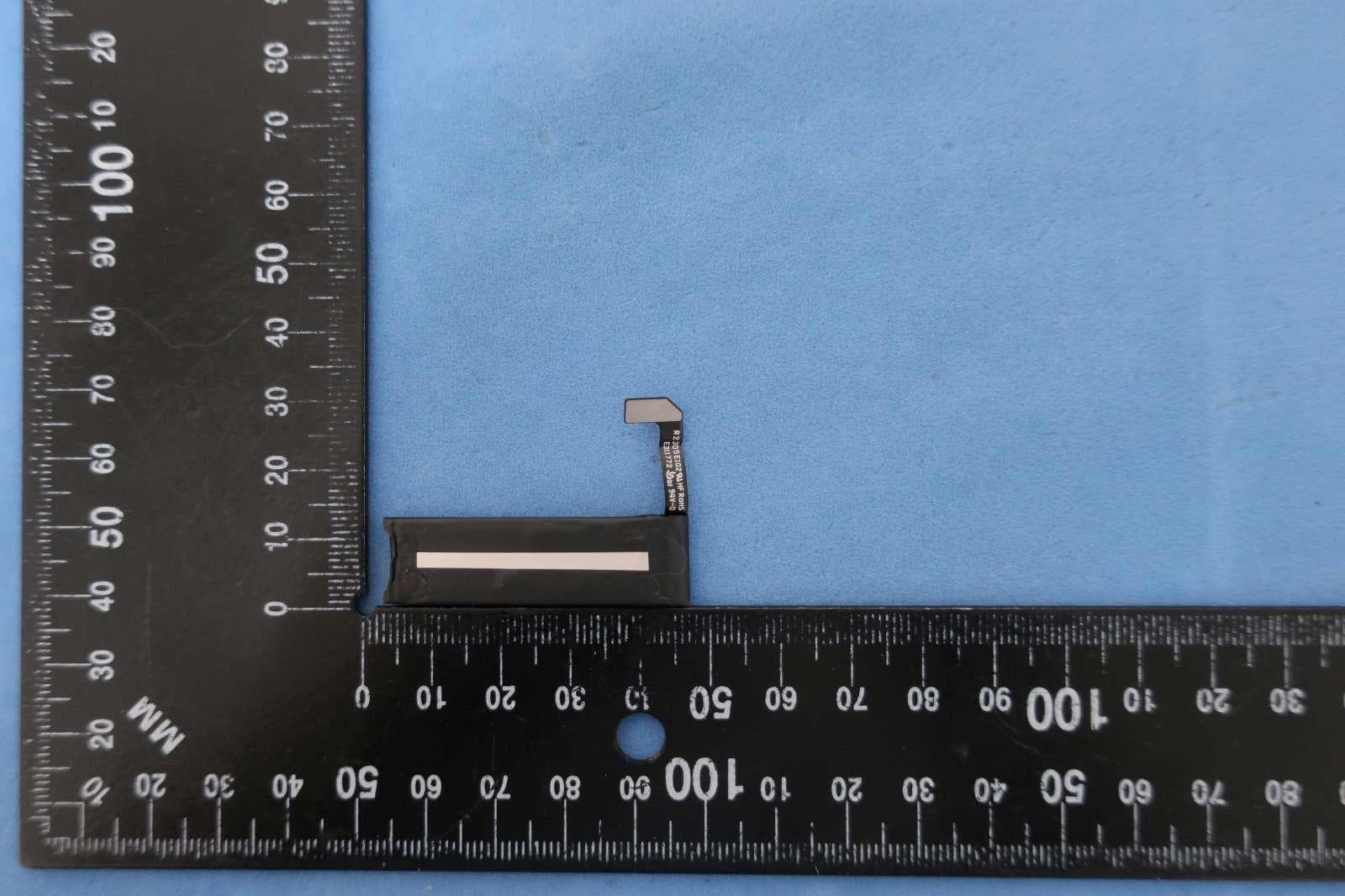
BXZSH4
Aug 02, 2023Myco 4 WiFi, Myco 4 Slim
Equipment Class
JBP - Part 15 Class B Computing Device Peripheral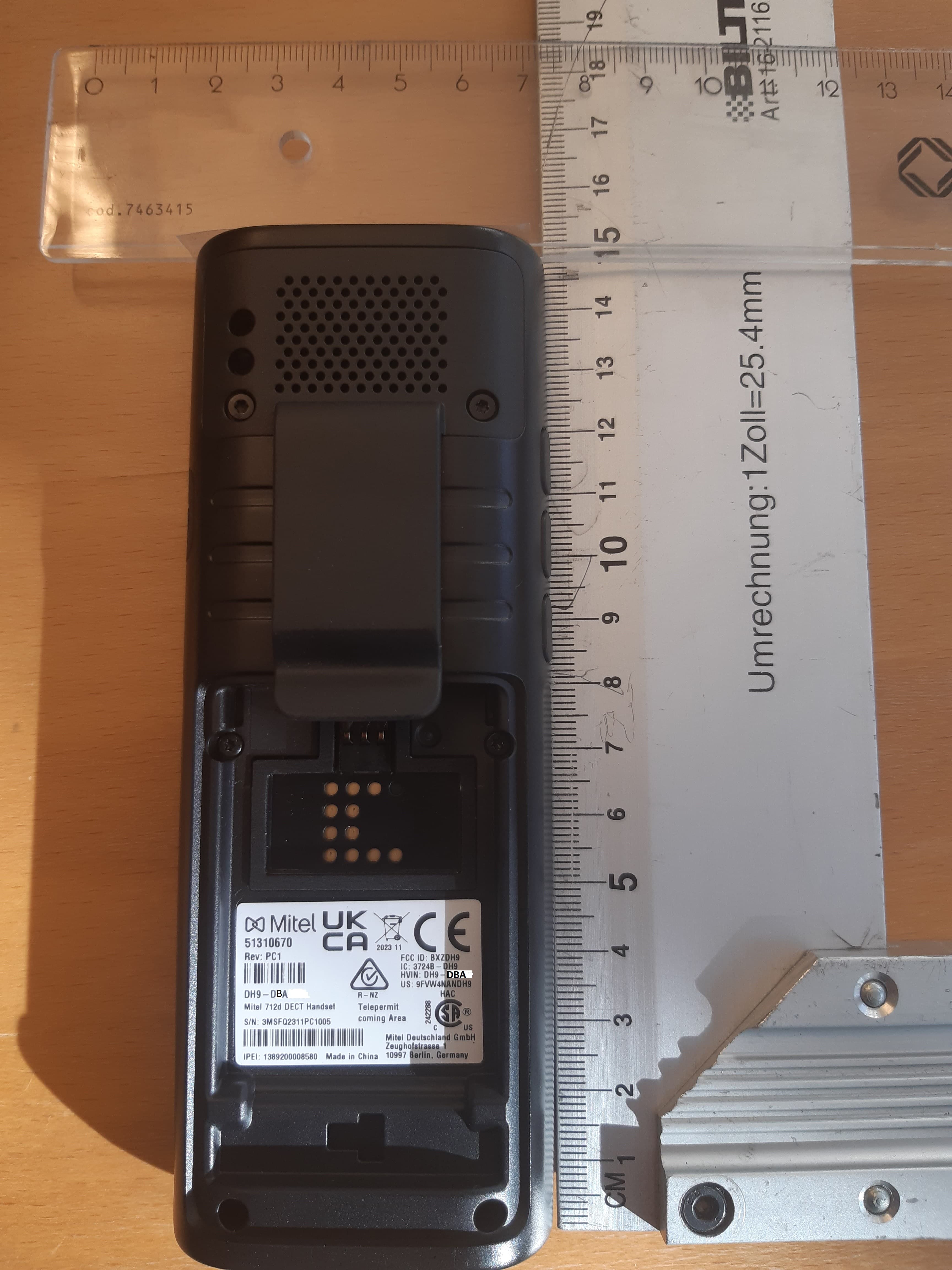
BXZDH9
Apr 16, 2023DECT Handset with Bluetooth
Equipment Class
PUE - Part 15 Unlicensed PCS portable Tx held to ear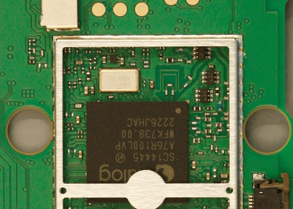
BXZDH10
Apr 16, 2023DECT Handset with Bluetooth
Equipment Class
DSS - Part 15 Spread Spectrum Transmitter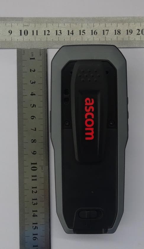
BXZDH8
Aug 09, 2021DECT Handset with Bluetooth and BLE
Equipment Class
JAB - Part 15 Class B Digital Device