BXZDB1R2ALegacy DECT Base Station
Ascom (Sweden) AB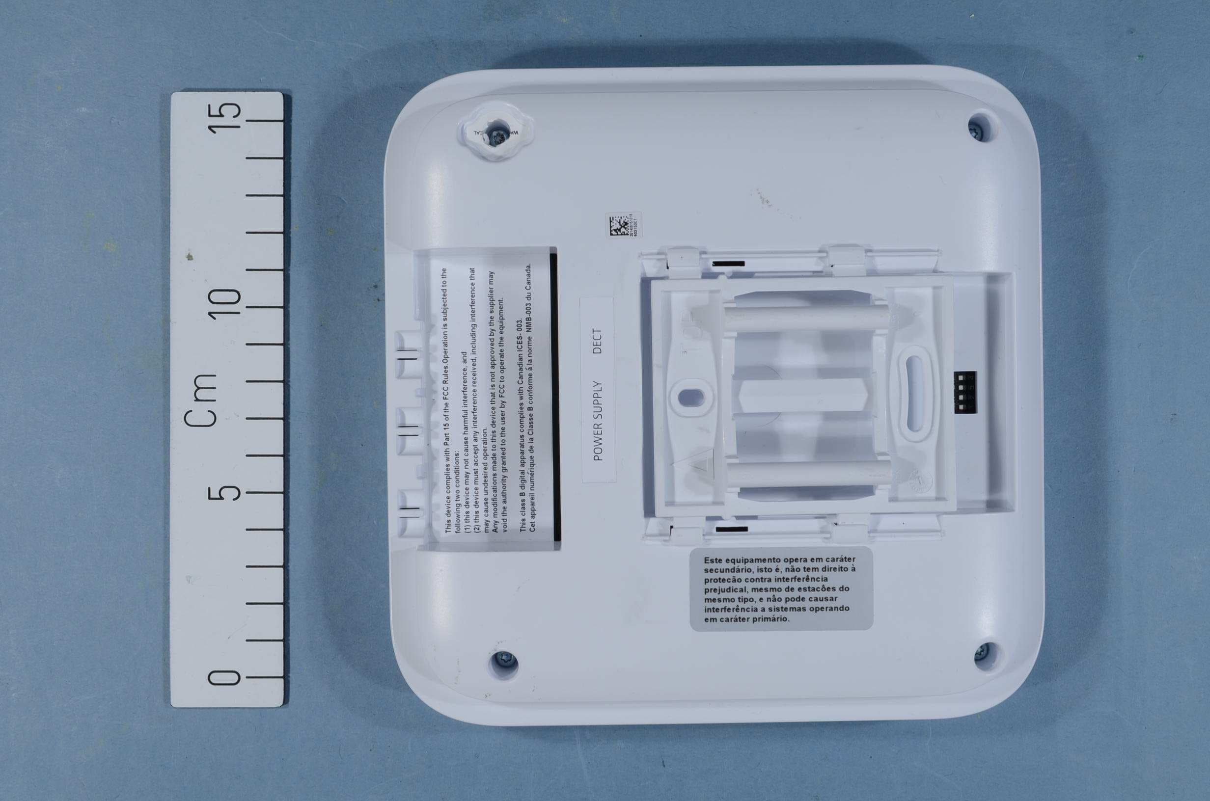
Click to zoom
Application Details
- Equipment Class
- PUB - Part 15 Unlicensed PCS Base Station
- Date of Grant
- Apr 09, 2015
- Application Purpose
- Original Equipment
- Date of Application
- Apr 09, 2015
- Equipment Note
- Legacy DECT Base Station
- Frequency Range
- 1921.53600000 - 1928.44800000
- Company
- Ascom (Sweden) AB
- Country
- Sweden
Documents & Files
Document Text
Text extracted from the exhibit documents filed with the FCC. Open a document above to read the original.
Users Manual
1 IPBS2/DB1 Safety Instructions Consignes de sécurité 2 Safety Instructions IPBS2/DB1 3 English ...................................................................................... 5 Français .................................................................................... 9 4 Safety Instructions IPBS2/DB1 English5 English Safety Instructions IPBS2/DB1 Read these instructions before installing the equipment. For safe and efficient operation of the equipment, observe these instructions and all necessary safety precautions when using the equipment. Follow the installation instructions and adhere to all warnings and safety precautions located on the product, and product manuals. Changes or modifications to the equipment not expressly approved by the party responsible for compliance could void the user’s authority to operate the equipment. Precautions • Save this manual. It includes important safety information and operating instructions. Save all instructions for future reference. • If local Power Supply is used for the equipment, the following power supplies can be used: For EU Art. No.: 130137B, Order No.: BSX-0013 For UK Art. No.: 130136B, Order No.: BSX-0014 For NA Art. No.: 130138A, Order No.: BSX-0015 For AU Art. No.: 130139B, Order No.: 660263 • Replace all guards, barriers, or fasteners. Close and secure all openings when you complete the installation or before you return the equipment to service. • Install all wiring according to local, state, and federal electrical code requirements. • Connect AC (power supply) only to designated power sources as marked on the product. • Danger: Never alter the AC cord or plug. If the plug will not fit into the outlet, have a proper outlet installed by a qualified electrician. Improper connection increases the risk of electric shock. • Ensure the AC receptacle is installed near the equipment and easily accessible. • When mounting the equipment on a wall, use fasteners supplied with the system. • Position the electrical cord to the AC power supply where it is least likely to be subjected to damage or stress. • Remove the electrical cord from an outlet by pulling gently on the AC adapter, not by pulling the cord. Safety Instructions IPBS2/DB1 6English Regulatory Compliance Statements (EU/EFTA only) This equipment is intended to be used in the whole EU & EFTA. This equipment is in compliance with the essential requirements and other relevant provisions of R&TTE Directive 1999/5/EC. The Declaration of Conformity may be consulted at: https://www.ascom-ws.com/doc/ The equipment is marked with the label Regulatory Compliance Statements (USA and Canada only) IPBS2 FCC ID: BXZIPBS2R2A IC: 3724B-IPBS2R2A DB1 FCC ID: BXZDB1R2A IC: 3724B-DB1R2A FCC compliance statements This equipment has been tested and found to comply with the limits for a Class B digital device, pursuant to part 15 of the FCC Rules. These limits are designed to provide reasonable protection against harmful interference in a residential installation. This equipment generates, uses and can radiate radio frequency energy and, if not installed and used in accordance with the instructions, may cause harmful interference to radio communications. However, there is no guarantee that interference will not occur in a particular installation. If this equipment does cause harmful interference to radio or television reception, which can be determined by turning the equipment off and on, the user is encouraged to try to correct the interference by one or more of the following measures: • Reorient or relocate the receiving antenna. • Increase the separation between the equipment and receiver. • Connect the equipment into an outlet on a circuit different from that to which the receiver is connected. • Consult the dealer or an experienced radio/TV technician for help. Safety Instructions IPBS2/DB1 English7 Information to user This device complies with Part 15 of the FCC Rules Operation is subject to the following two conditions: 1. this device may not cause harmful interference, and 2. this device must accept any interference received, including interference that may cause undesired operation. This device complies with Industry Canada licence-exempt RSS standard(s). Operation is subject to the following two conditions: 1. this device may not cause interference, and 2. this device must accept any interference, including interference that may cause undesired operation of the device. Le présent appareil est conforme aux CNR d'Industrie Canada applicables aux appareils radio exempts de licence. L'exploitation est autorisée aux deux conditions suivantes: 1. l'appareil ne doit pas produire de brouillage, et 2. l'utilisateur de l'appareil doit accepter tout brouillage radioélectrique subi, même si le brouillage est susceptible d'en compromettre le fonctionnement. IC Requirements for Canada This Class B digital apparatus complies with Canadian ICES-003. Cet appareil numérique de la Classe B conforme á la norme NMB- 003 du Canada. Modifications Changes or modifications to the equipment not expressly approved by the party responsible for compliance could void the user’s authority to operate the equipment. Exposure to radio frequency signals This device complies with FCC RF radiation exposure limits set forth for an uncontrolled environment. The antenna used for this transmitter must be installed to provide a separation distance of at least 20 cm from all persons and must not be co-located or operating in conjunction with any other antenna or transmitter. Safety Instructions IPBS2/DB1 8English Consignes de sécurité IPBS2/DB1 Français9 Français Consignes de sécurité IPBS2/DB1 Lisez les présentes instructions avant d'installer l'équipement. Pour un fonctionnement sûr et efficace de l'équipement, conformez-vous aux présentes instructions et prenez toutes les précautions de sécurité nécessaires lors de son utilisation. Suivez les instructions d'installation et observez tous les avertissements et les précautions de s…
Text truncated - open the document above for the full version.
External Photos
EXTERNAL PHOTOS Project no.: 271164 FCC ID: BXZDB1R2A Page 1 (1) EXTERNAL PHOTOS
ID Label/Location Info
Fabriqué en Chine Fabriqué en Chine on อ ุปกรณ โทรคมนาคมน ี้เป ็ นไปตามข อก ํ าหนดของคณะกรรมการก ิ จการโทรคมนาคมแห งชาต ิ Made in China off 1 2 3 4 EU: on on on on CH: off on on on SA: on off on on NA: off off on on 21-56 VDC ; 100 mA FCC ID: BXZDB1R2AIC: 3724B-DB1R2A Insert date code at time of label printing. FCC ID: BXZDB1R2AIC: 3724B-DB1R2A RCM mark Australia: Height > 3mm Complies withIDA StandardsDA103861 242288 242288 Made in China Label specification 4888 37684/SDPPI/2014 The symbol indicating separate collection for EEEconsists of the crossed-out wheeled bin. The symbol must be printed visibly, legibly and indelibly. This document contains confidential and proprietary information of Ascom and may not be copied, used or disclosed without the w ritten permission of Ascom and must be returned upon request. 21-56 VDC ; 100 mA When used, the CE mark must have a height of at least 5 mm.Serial number, 8 characters.S/N: Barcode is code 128 format. Ascom (Sweden) ABGrimbodalen 2417 49 GöteborgSweden Ascom (Sweden) ABGrimbodalen 2417 49 GöteborgSweden Label type: FCC labelTotal size: 66*35 mm Label type: DB1 Box labelTotal size: 66*35 mm Label type: DB1 Product labelTotal size: 58.6*68.4 mm Label pn: LBL0322 Label revision: A9 Product: DB1 there /xx is the product revision Latest updated: 2015-01-20 Signature: Psg S/N: S/N: This device complies with Part 15 of the FCC Rules.Operation is subjected to the following two conditions:(1) this device may not cause harmful interference, and (2) thisdevice must accept any interference received, includinginterference that may cause undesired operation.Any modifications made to this device that is not approved by thesupplier may void the authority granted to the user by FCC tooperate the equipment.This class B digital apparatus complies with Canadian ICES-003.Cet appareil numérique de la Classe B conforme á lanormeNMB-003 du Canada. S/NyyWww T26xxxxxxx yyWww ≥ 5mm T26xxxxxxx yyWww Model:DB1-A3A Model:DB1-A3A
ID Label/Location Info
onoff XXXX-XX-XXXX Anatel marking for Brazil 1 2 3 4 EU: on on on on 1900-1920 MHz: off on on on SA: on off on on NA: off off on on 21-56 VDC ; 100 mA PTC220/13/032 PTC220/13/032 FCC ID: BXZDB1R2AIC: 3724B-DB1R2A 80E00014AAA-Ayy 80E00014AAA-Ayy Insert date code at time of label printing. 1130-09-5062 1130-09-5062 FCC ID: BXZDB1R2AIC: 3724B-DB1R2A RCM mark Australia: Height > 3mm 242288 BS332 BS332 242288 Made in China Logo: Leave on > 1/2 M(first letter in Mitel) size spacing when possible Label specification Made in China 0789XXXXXXXXXX The symbol indicating separate collection for EEEconsists of the crossed-out wheeled bin. The symbol must be printed visibly, legibly and indelibly. 07898935519017 This document contains confidential and proprietary information of Ascom and may not be copied, used or disclosed without the w ritten permission of Ascom and must be returned upon request. 07898935519017 21-56 VDC ; 100 mA When used, the CE mark must have a height of at least 5 mm.Serial number, 8 characters. Note for Anatel marking:1. Fonts need to be Arial, black and minimum heigt of 1 mm2. EAN- 128- formated barcode. Minimum width is 24 mm and height 3.6 mm. 2.5 mm of plain space to left and right of barcode. Must not contain (01)3 The height of the logo > 4mm and the surounding space of the logo at least half of this height. S/N: Barcode is code 128 format. Mitel, Castlegate Business ParkPortskewett, MonmouthshireNP26, 5YR, UK Label type: FCC labelTotal size: 66*35 mm Label type: DB1 Box labelTotal size: 66*35 mm Mitel, Castlegate Business ParkPortskewett, MonmouthshireNP26, 5YR, UK Label type: DB1 Product labelTotal size: 58.6*68.4 mm Label pn: LBL0323 Label revision: A7 Product: DB1 Variant: DB1- B3/xx = 80E00014 AAA-Ayy there /xx and /yy is the product revision Latest updated: 2015-01-07 Signature: Psg S/N: S/N: This device complies with Part 15 of the FCC Rules.Operation is subjected to the following two conditions:(1) this device may not cause harmful interference, and (2) thisdevice must accept any interference received, includinginterference that may cause undesired operation.Any modifications made to this device that is not approved by thesupplier may void the authority granted to the user by FCC tooperate the equipment.This class B digital apparatus complies with Canadian ICES-003.Cet appareil numérique de la Classe B conforme á lanormeNMB-003 du Canada. S/NyyWww 1234567890 yyWww ≥ 5mm 1234567890 (01) yyWww (01) Model:DB1-B3A Model:DB1-B3A
ID Label/Location Info
LBL_DB1-C3A_Avaya_Ver10 - Common Markets Product:Brand:Avaya 2015/03/04 Product label 1Best fit label size:Comments Product label 2Comments Box label 1:66x35250676B 250691A 3-4: Location code. AD = HJA, AM = Flex, Do considered week 01, even if a portion of that w Avaya S/N format: 1-2: Year After repair, add "R" after Avaya ́s art.nr 8-12: Unique code. Can be restarted every da 5-6: Week. The week that January 1 falls into At product?At box?At product?At box? 73,6x32,1Best fit label size: Best fit label size: Nr. 4 LBL0324 Read this first! This file is used for one product (Designator + Variants) and one brand only. Different marking can occur for differen If possible, we use one label with the assembled information for all common markets. If not possible (e.g. due to lack of space on the one worksheet represent one market. EU/EFTA, US, CAN, RUS Latest updated: Market for this label: Eventually future market for product: DB1-C3A 250690B58,6x68,4 December previous year. 7: Day. 0 i Saturday The 2D code consists of UN125337134 + asc Best fit label size: /xx=Product revision Nr. 3Best fit label size: Best fit label size: LBL_DB1-C3A_Avaya_Ver10 - Common Markets umen week is ay is t markets. label), com SN
ID Label/Location Info
LBL_DB1-C5A_Avaya_Ver5 - Common Markets Product:Brand:Avaya 2015/03/05 Product label 1Best fit label size:Comments Product label 2Comments Box label 1:66x35250676B Nr. 3Best fit label size: Best fit label size: The 2D code consists of UN125337134 + asc Best fit label size: /xx=Product revision 250690B58,6x68,4 December previous year. 7: Day. 0 i Saturday Nr. 4 LBL0487 Read this first! This file is used for one product (Designator + Variants) and one brand only. Different marking can occur for differen If possible, we use one label with the assembled information for all common markets. If not possible (e.g. due to lack of space on the one worksheet represent one market. US, EU Latest updated: Market for this label: Eventually future market for product: DB1-C5A 8-12: Unique code. Can be restarted every da 5-6: Week. The week that January 1 falls into At product?At box?At product?At box? 73,6x32,1Best fit label size: Best fit label size: 250691A 3-4: Location code. AD = HJA, AM = Flex, Do considered week 01, even if a portion of that w Avaya S/N format: 1-2: Year After repair, add "R" after Avaya ́s art.nr LBL_DB1-C5A_Avaya_Ver5 - Common Markets com SN t markets. label), ay is umen week is
Internal Photos
INTERNAL PHOTOS Project no.: 271164 FCC ID: BXZDB1R2A Page 1 (2) INTERNAL PHOTOS Internal Photos With Shielding INTERNAL PHOTOS Project no.: 271164 FCC ID: BXZDB1R2A Page 2 (2) Without Shielding
RF Exposure Info
FCC ID: BXZDB1RA2 MPE Calculation for FCC Uncontrolled Environment Formula from page 18 of OET Bulletin 65, Edition 97 -01 where: S = power densityP = power input to the antennaG = power gain of the antenna in the direction of i nterest relative to an isotropic radiator R = distance to the center of radiation of the ante nna Source Based Time Averaged Duty Cycle is 100% in ca lculation below Maximum peak output power at antenna input terminal : 19.20 (dBm) Maximum peak output power at antenna input terminal : 0.083 (W) Maximum antenna gain: 0.60 (dBi) Maximum antenna gain: 1.148 (numeric) Prediction distance: 20 (cm) Prediction frequency: 1925 (MHz) Time Averaged Duty Cycle 100 % MPE limit for uncontrolled exposure at prediction f requency: 10.00 (W/m^2) Power density at prediction frequency: 0.0190 (mW/cm^2) Power density at prediction frequency: 0.190 (W/m^2) Maximum allowable antenna gain: 17.81 (dBi) Margin of Compliance: 17.21 (dB) 2 4 R PG S π =
Test Report
Report No. 271164-6 Template version: B Nemko Norway Nemko AS, Instituttveien 6, P.O. Box 96 Kjeller, 2007 Kjeller, Norway TEL +47 22 96 03 30 FAX +47 22 96 05 50 EMAIL [email protected] ENTERPRISE NUMBER NO974404532 nemko.com/no Test Report Product UPCS Base Station with 4-wire interface Name and address of the applicant Ascom Sweden AB P.O.Box 8783, Grimbodalen 2, SE-402 76 Gothenburg, Sweden Name and address of the manufacturer Same as above Model DB1-A3A, DB1-B3A, DB1-C3A, DB1-C5A Rating 48V DC Trademark Ascom Serial number / Additional information DECT 6.0 Tested according to FCC Part 15, subpart D Isochronous UPCS Device, 1920 – 1930 MHz Industry Canada RSS 213, Issue 2 2 GHz License-exempt Personal Communications Service Devices (LE-PCS) Order number 271164 Tested in period 2014.10.02 to 2014.10.03 Issue date 2015.03.06 Name and address of the testing laboratory Instituttveien 6 Kjeller, Norway FCC No: 994405 IC OATS: 2040D-1 TEL: (+47) 22 96 03 30 FAX: (+47) 22 96 05 50 Prepared by [Frode Sveinsen] Approved by [G.Suhanthakumar] This report shall not be reproduced except in full without the written approval of Nemko. Opinions and interpretations expressed within this report are not part of the current accreditation. This report was originally distributed electronically with digital signatures. For more information contact Nemko. TEST REPORT FCC part 15D Report no.: 271164-6 FCC ID: BXZDB1RA2 Nemko Norway, Instituttveien 6, Kjeller, Norway Page 2 (44) CONTENTS 1 INFORMATION ................................................................................................................................. 3 1.1 Tested Item........................................................................................................................................ 3 1.2 Description of Tested Device ............................................................................................................. 3 1.3 Exposure Evaluation .......................................................................................................................... 3 1.4 Test Environment .............................................................................................................................. 4 1.5 Test Engineer(s) ................................................................................................................................ 4 1.6 Test Equipment ................................................................................................................................. 4 1.7 Other Comments ............................................................................................................................... 4 2 TEST REPORT SUMMARY .............................................................................................................. 5 2.1 General .............................................................................................................................................. 5 2.2 Test Summary ................................................................................................................................... 6 3 TEST RESULTS ................................................................................................................................ 7 3.1 Power Line Conducted Emissions ..................................................................................................... 7 3.2 Digital Modulation Techniques .......................................................................................................... 9 3.3 Labeling Requirements ..................................................................................................................... 9 3.4 Channel Frequencies ........................................................................................................................ 9 3.5 Antenna Requirement...................................................................................................................... 10 3.6 Automatic Discontinuation of Transmission .................................................................................... 10 3.7 Peak Power Output ......................................................................................................................... 11 3.8 Emission Bandwidth B ..................................................................................................................... 14 3.9 Power Spectral Density ................................................................................................................... 17 3.10 In-Band Unwanted Emissions, Conducted ...................................................................................... 20 3.11 Out-of-band Emissions, Conducted................................................................................................. 22 3.12 Carrier Frequency Stability .............................................................................................................. 26 3.13 Frame Repetition Stability ............................................................................................................... 27 3.14 Frame Period and Jitter ................................................................................................................... 27 3.15 Monitoring Threshold, Least Interfered Channel ............................................................................. 29 3.16 Threshold Monitoring Bandwidth ..................................................................................................... 31 3.17 Reaction Time and Monitoring Interval ............................................................................................ 32 3.18 Time and Spectrum Window Access Procedure ............................................................................. 34 3.19 Acknowledgements and Transmission Duration ............................................................................. 38 3.20 Dual Access Criteria Check ...................…
Text truncated - open the document above for the full version.
Test Setup Photos
TEST SET-UP PHOTOS Project no.: 271164 FCC ID: BXZDB1RA2 Page 1 (1) PHOTOS OF TEST SET-UP – Ascom DB1 Radiated Emissions 30 - 200 MHz Power line Conducted Emissions Test
Contact Information
Applicant
Peter Soderberg
Test Firm
Nemko ASFrode Sveinsen
Technical Specifications
| # | Rule Parts | Frequency Range | Power Output |
|---|---|---|---|
| 1 | 15D | 1.92 GHz - 1.93 GHz | 83.00 mW |
Other Applications from Ascom (Sweden) AB

BXZCHAT2
Sep 27, 2023Narrow band alarm transceiver
Equipment Class
TNB - Licensed Non-Broadcast Station Transmitter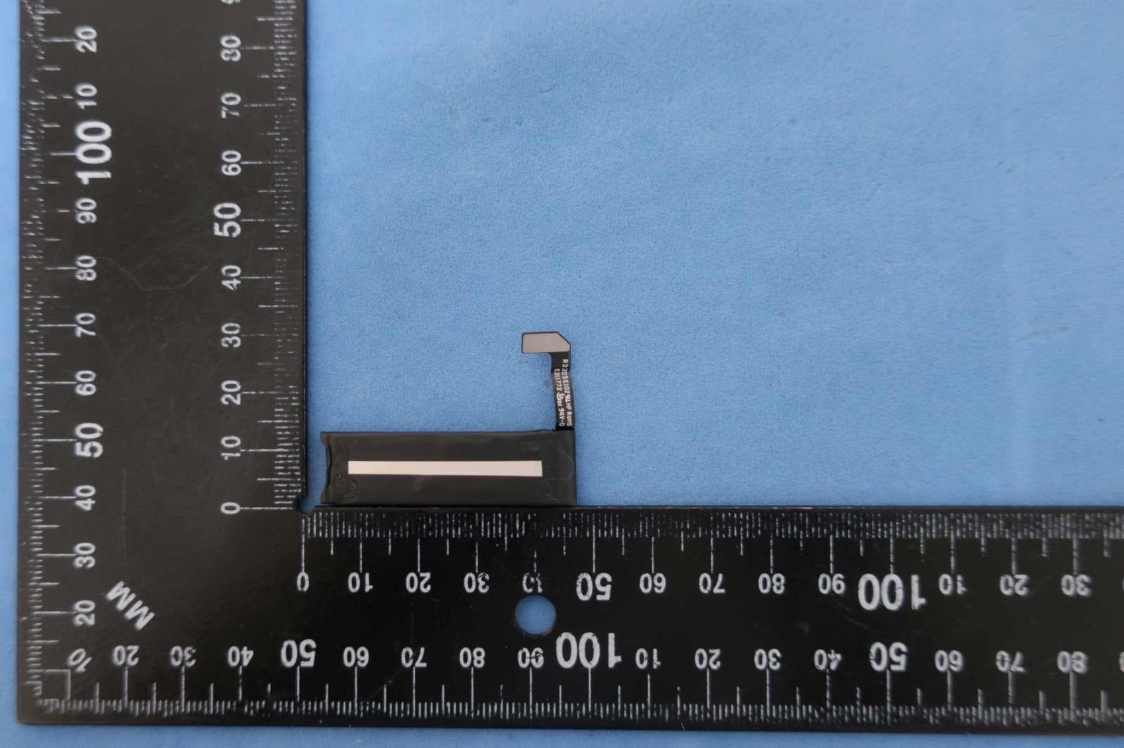
BXZSH4
Aug 02, 2023Myco 4 WiFi, Myco 4 Slim
Equipment Class
JBP - Part 15 Class B Computing Device Peripheral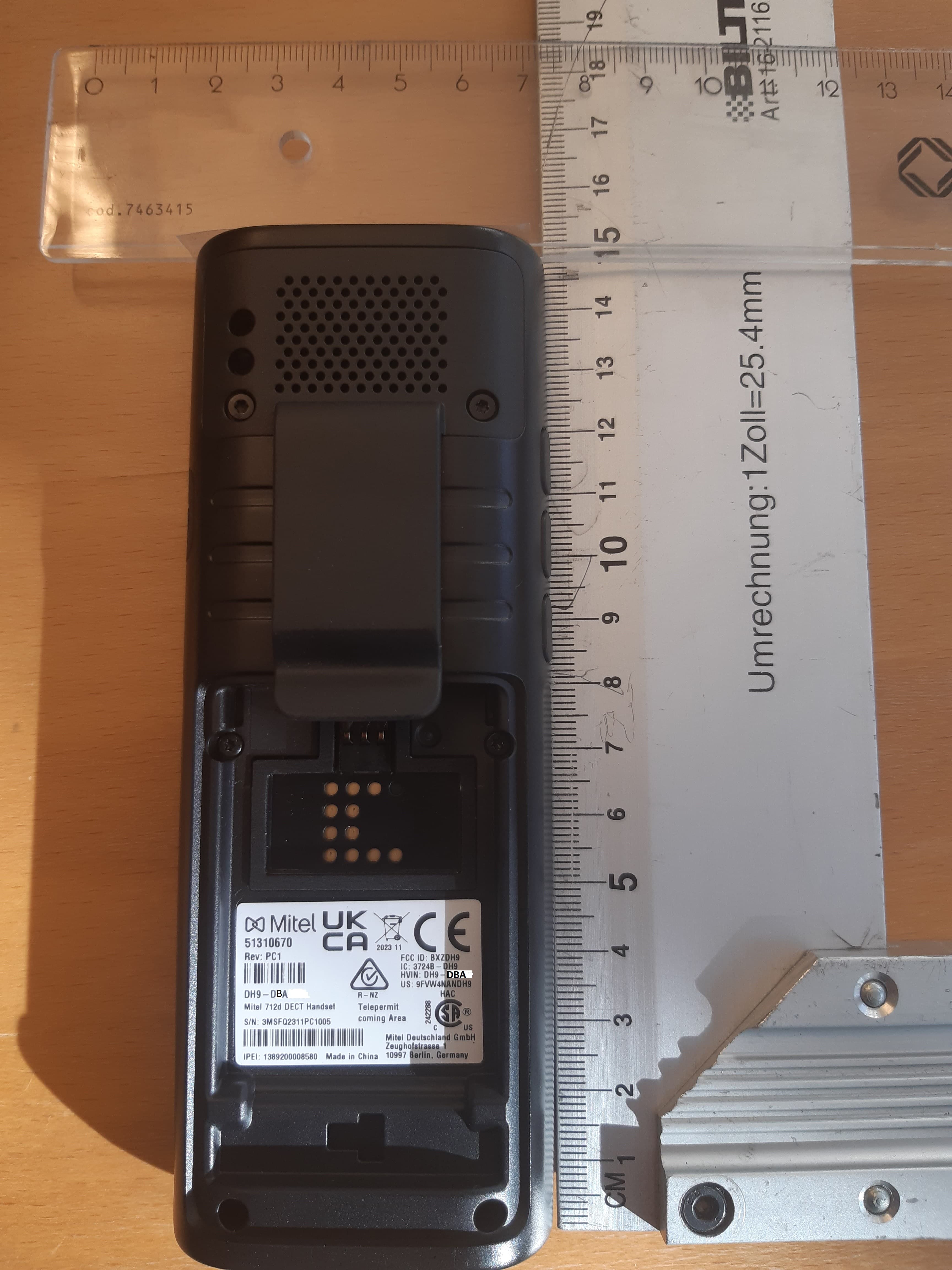
BXZDH9
Apr 16, 2023DECT Handset with Bluetooth
Equipment Class
PUE - Part 15 Unlicensed PCS portable Tx held to ear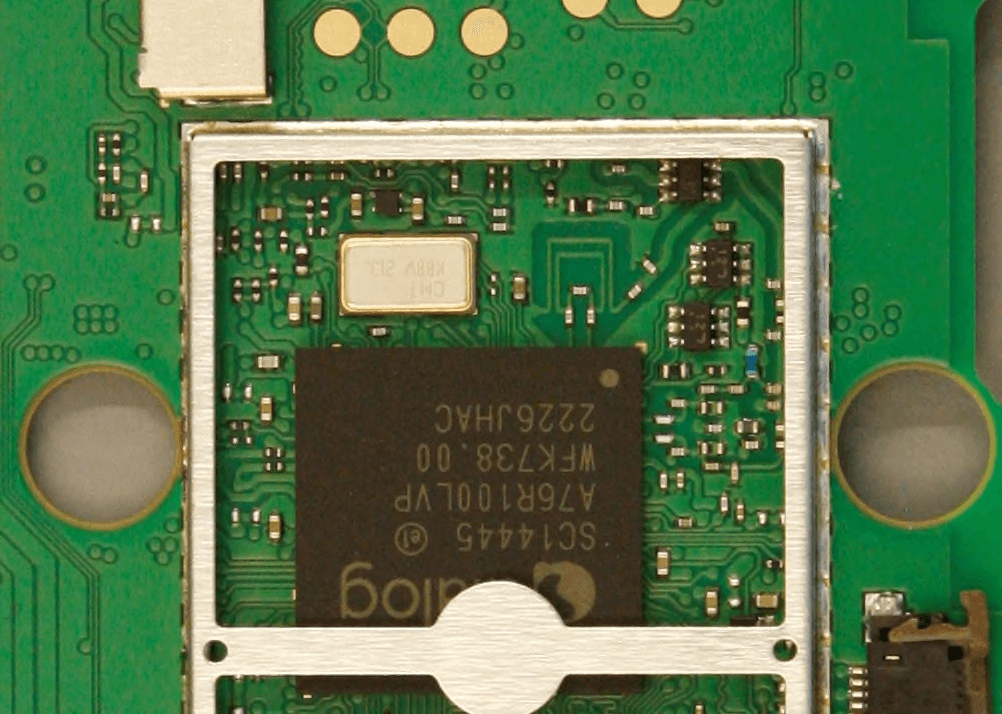
BXZDH10
Apr 16, 2023DECT Handset with Bluetooth
Equipment Class
DSS - Part 15 Spread Spectrum Transmitter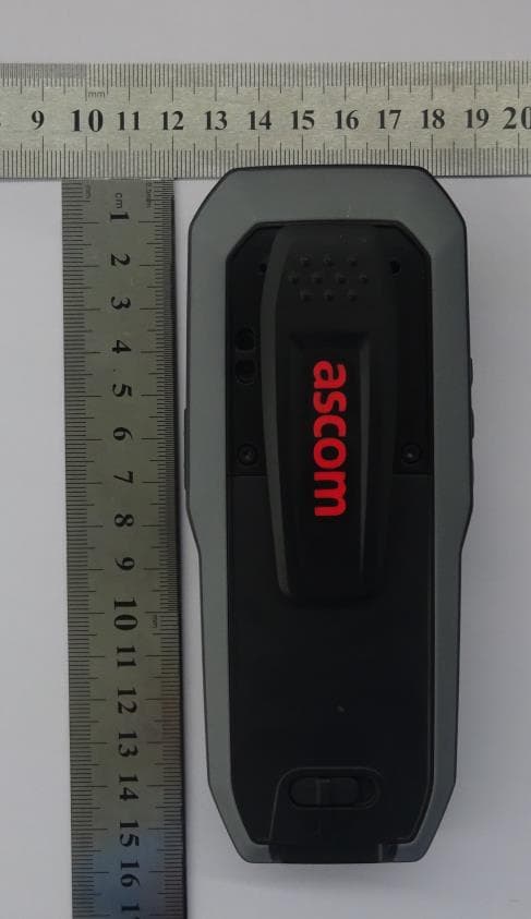
BXZDH8
Aug 09, 2021DECT Handset with Bluetooth and BLE
Equipment Class
JAB - Part 15 Class B Digital Device