BXZL951LPLF �Transmitter TeleProtect
Ascom (Sweden) AB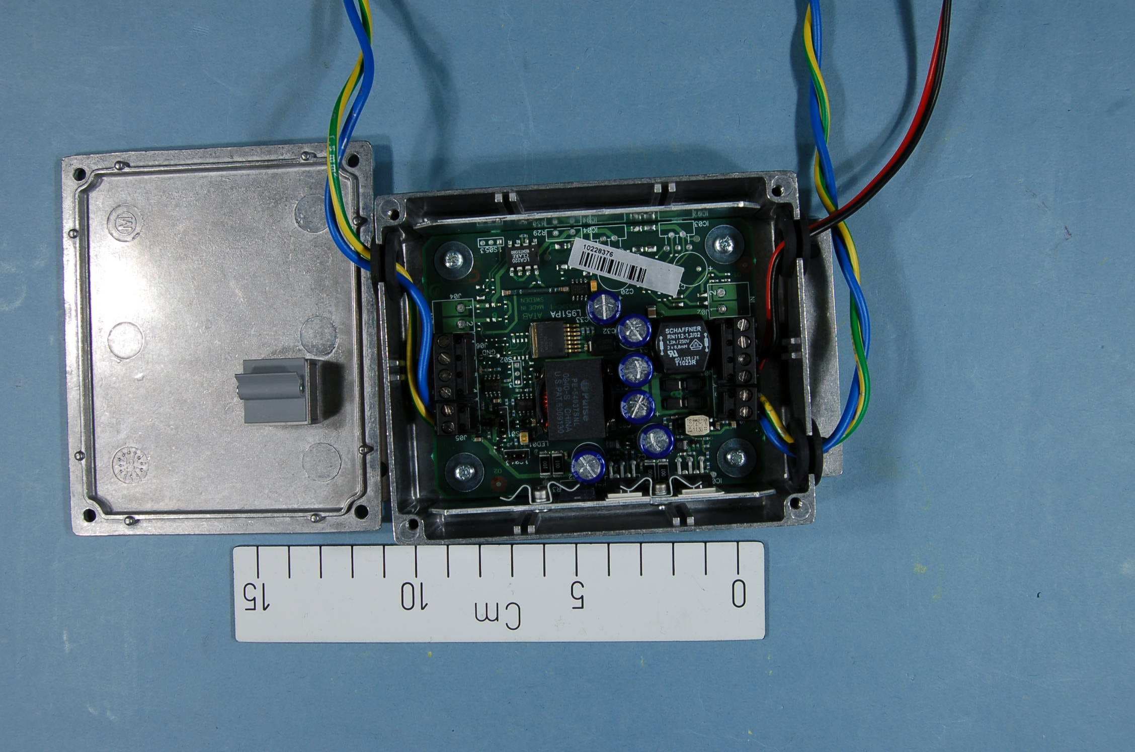
Click to zoom
Application Details
- Equipment Class
- DCD - Part 15 Low Power Transmitter Below 1705 kHz
- Date of Grant
- May 07, 2012
- Application Purpose
- Original Equipment
- Date of Application
- May 07, 2012
- Equipment Note
- LF �Transmitter TeleProtect
- Frequency Range
- 0.04000000 - 0.04000000
- Company
- Ascom (Sweden) AB
- Country
- Sweden
Documents & Files
Document Text
Text extracted from the exhibit documents filed with the FCC. Open a document above to read the original.
Users Manual
TD 92082GB PRELIMINARY 7 May 2012 / Ver. PB7 Installation Guide L951LP Locator L951A1 Antenna Unit L951A2 Antenna Unit L951A2/2 Antenna Unit L951PA Power Amplifier L951TP Transient Protection Unit TD 92082GB PRELIMINARY 7 May 2012 / Ver. PB7 Installation Guide LF Location Units Contents 1 Introduction ................................................................................................................... 1 1.1 Regulatory Compliance Statements (EU/EFTA only) ...................................................... 2 1.2 Regulatory Compliance Statements (USA and Canada only) ....................................... 2 2 Board Descriptions ......................................................................................................... 3 2.1 L951LP Locator ........................................................................................................................ 3 2.2 L951A1 Antenna Unit ............................................................................................................ 4 2.3 L951A2 and L951A2/2 Antenna Units ............................................................................. 5 2.4 L951PA Power Amplifier ........................................................................................................ 6 3 Installation...................................................................................................................... 7 3.1 Mounting .................................................................................................................................... 7 3.1.1 L951LP Locator............................................................................................................... 7 3.1.2 L951A1 Antenna Unit .................................................................................................. 8 3.1.3 L951A2 Antenna Unit................................................................................................... 8 3.1.4 L951A2/2 Antenna Unit .............................................................................................. 9 3.1.5 L951PA Power Amplifier ........................................................................................... 10 3.1.6 L951TP Transient Protection Unit ......................................................................... 10 3.2 L951LP Locator...................................................................................................................... 11 3.2.1 Connecting Supply Voltage....................................................................................... 11 3.2.2 Setting Location Code ................................................................................................ 11 3.2.3 Enabling Immediate Alarm Transmission ............................................................. 12 3.2.4 Enabling Internal Antenna ........................................................................................ 12 3.2.5 Connecting Antenna Units ........................................................................................ 13 3.2.6 Connecting Loops ........................................................................................................ 14 3.2.7 Connecting Power Amplifier ..................................................................................... 15 3.2.8 Adjusting the Range .................................................................................................. 16 3.3 L951PA Power Amplifier ..................................................................................................... 16 3.3.1 Connecting Supply Voltage....................................................................................... 16 3.3.2 Connecting Antenna Unit .......................................................................................... 17 3.4 L951TP Transient Protection Unit .................................................................................... 18 3.5 Locator Monitoring ............................................................................................................... 19 4 Installation Check ........................................................................................................ 20 TD 92082GB PRELIMINARY 7 May 2012 / Ver. PB7 Installation Guide LF Location Units 1 1Introduction Figure 1. L951LP Locator, L951A1 Antenna Unit and L951A2 Antenna Unit. The Locator L951LP is a dual output low frequency (LF) inductive location transmi tter. It is used in the Ascom Paging System and Ascom IP-DECT System, when location function is required. It generates coded signals to modulate a magnetic field carrier. Alarm Transmitters designed for LF can be used to identify the location from where an alarm is generated. L951LP has two antenna channels. Either the internal antenna and one external Antenna Unit (L951A1, L951A2, L951A2/ 2, indoor or outdoor loops) or two external Antenna Units can be used for transmission. The Antenna Units connected to L951LP can either cover a larger or additional area with the same code, or different areas with code and code + 1. When L951LP i s used to drive outdoor loops, the L951TP (Transient Protection) must be mounted for protection against lightning strikes. L951PA Power Amplifier is used when the transmitting range compared to L951LP has to be extended. The Power Am plifier is connected to the Locator unit and can feed one Antenna Unit (L951A1, L951A2, or L951A2/2). The Power Amplifier does not have any internal antenna. The following procedure describes the installation of L951LP Locator , Antenna Units (L951A1, L951A2, L951A2/2), L951PA Power Amplifier, and L951TP Transient Protection Unit. As a complement to this Installation Guide, see the S ystem Installation document. UnitSupply voltagePower consumption L951LP15–28 V AC or 16–40 V DC3 W L951A1none (passive) L951A2none (passive) L951A2/2none (passive) L951PA15–28 V AC or 16–40 V DC5.7 W L951TPnone (passive) IMPORTANT: Protect the unit against current …
Text truncated - open the document above for the full version.
External Photos
Project no.: 193638 Page 1 of 5 EXTERNAL PHOTOS – ASCOM ASCOM L951PA Project no.: 193638 Page 2 of 5 ASCOM L951A1 Project no.: 193638 Page 3 of 5 ASCOM L951A1 Project no.: 193638 Page 4 of 5 ASCOM L951LP/1A Project no.: 193638 Page 5 of 5 ASCOM L951LP/1A
Test Report
Nemko AS, Gaustadalléen 30, P.O.Box 73 Blindern, NO-0314 Oslo Norway T +47 22 96 03 30 F +47 22 96 05 50 Enterprise number NO974404532 Visiting address: Nemko Kjeller, Instituttveien 6, P.O.Box 96, NO-2027 Kjeller Norway T +47 64 84 57 00 F +47 64 84 57 05 Test report no. : 193638-1 Item tested : L951LP Type of equipment : LF Locator FCC ID : BXZL951LP IC : 3724B-L951LP Client : Ascom Sweden AB FCC Part 15C Power Line conducted emission (15.207) and Radiated emissions (15.209) RSS-GEN, Issue 3 General Requirements and Information for the Certification of Radio Apparatus 2012-04-27 Authorized by : .............................................. Geir Antonsen Technical Verificator TEST REPORT FCC part 15.209 Ref. no.: 193638-1 FCC ID: BXZL951LP Nemko AS, NO-2027 Kjeller Page 2 (16) CONTENTS 1 GENERAL INFORMATION ...................................................................................................... 3 1.1 Testhouse Info .......................................................................................................................... 3 1.2 Client Information ...................................................................................................................... 3 1.3 Responsible Manufacturer (If other than client) ........................................................................ 3 2 Test Information ...................................................................................................................... 4 2.1 Test Item ................................................................................................................................... 4 2.2 Test Environment ...................................................................................................................... 6 2.2.1 Normal test condition ................................................................................................... 6 2.3 Test Period................................................................................................................................ 6 3 TEST REPORT SUMMARY ..................................................................................................... 7 3.1 General ..................................................................................................................................... 7 3.2 Test Summary ........................................................................................................................... 8 3.3 Description of modification for Modification Filing ..................................................................... 8 3.4 Comments ................................................................................................................................ 8 3.5 Family List Rational .................................................................................................................. 8 4 TEST RESULTS ....................................................................................................................... 9 4.1 20 dB Bandwidth ....................................................................................................................... 9 4.2 Power Line Conducted Emissions .......................................................................................... 10 4.3 Spurious Emissions (Radiated) .............................................................................................. 12 5 LIST OF TEST EQUIPMENT .................................................................................................. 15 6 BLOCK DIAGRAM ................................................................................................................. 16 6.1 Power Line Conducted Emission ............................................................................................ 16 6.2 Test Site Radiated Emission ................................................................................................... 16 TEST REPORT FCC part 15.209 Ref. no.: 193638-1 FCC ID: BXZL951LP Nemko AS, NO-2027 Kjeller Page 3 (16) 1 GENERAL INFORMATION 1.1 Testhouse Info Name : Nemko AS Address : Nemko Kjeller Instituttveien 6, Box 96 NO-2027 Kjeller, NORWAY Telephone : +47 64 84 57 00 Fax : +47 64 84 57 05 E-mail: [email protected] FCC test firm : 994405 IC OATS : 2040D-1 Total Number of Pages: 16 1.2 Client Information Name : Ascom Sweden AB Address : Grimbodalen 2, P.O.Box 8783, SE-40276 Gotenberg, Sweden. Telephone : +46 31 55 94 16 Fax : +46 31 55 20 31 Contact: Name : Gilbert Kristiensson Telephone : +46 31 55 94 16 E-mail : [email protected] 1.3 Responsible Manufacturer (If other than client) Name : / Address : / TEST REPORT FCC part 15.209 Ref. no.: 193638-1 FCC ID: BXZL951LP Nemko AS, NO-2027 Kjeller Page 4 (16) 2 Test Information 2.1 Test Item Name : Ascom FCC ID : BXZL951LP IC : 3724B-L951LP Model/version : L951LP Serial number : / Hardware identity and/or version: / Software identity and/or version : / Frequency Range : 40kHz Number of Channels : / Type of Modulation : FSK User Frequency Adjustment : None Type of Power Supply : DC 24V Antenna Connector : Integral Antenna Diversity Supported : No Desktop Charger : None Description of Test Item L951LP is an LF transmitter with a configurable ID that gives a unique location from each transmitter (Stand-alone) Exposure Evaluation The EUT is exempted from RF Exposure Evaluation. TEST REPORT FCC part 15.209 Ref. no.: 193638-1 FCC ID: BXZL951LP Nemko AS, NO-2027 Kjeller Page 5 (16) TEST REPORT FCC part 15.209 Ref. no.: 193638-1 FCC ID: BXZL951LP Nemko AS, NO-2027 Kjeller Page 6 (16) 2.2 Test Environment 2.2.1 Normal test condition Temperature: 20 – 22 °C Relative humidity: 27 – 36 % Normal test voltage: 12V DC The values are the limit registered during the test period. 2.3 Test Period Item received date: 2012-01-26 Test period : 2012-01-26 TEST REPORT FCC part 15.209 Ref. no.: 193638-1 FCC ID: BXZL951LP Nemko AS, NO-2027 Kjeller Page 7 (16) 3 TEST REPORT SUMMARY 3.1 General Manufact…
Text truncated - open the document above for the full version.
Test Setup Photos
Project no.: 193638 Page 1 of 2 PHOTOS OF TEST SET-UP – ASCOM Power-line Conducted Emissions Test Set-up Project no.: 193638 Page 2 of 2 Radiated emission 30 - 1000MHz Test Set-up Radiated emission 9kHz – 30MHz Test Set-up
Contact Information
Applicant
Peter Soderberg
Technical Contact
Ascom (Sweden) ABGilbert Kristensson
[email protected]46 31 559 416
P.O.Box 8783, Grimbodalen 2 · Goteborg · Sweden
Non-Technical Contact
Ascom (Sweden) ABLena Kindmark
[email protected]46 31 559 432
Test Firm
Nemko ASFrode Sveinsen
Technical Specifications
| # | Rule Parts | Frequency Range | Power Output |
|---|---|---|---|
| 1 | 15C | 0.04 MHz - 0.04 MHz | - |
Other Applications from Ascom (Sweden) AB

BXZCHAT2
Sep 27, 2023Narrow band alarm transceiver
Equipment Class
TNB - Licensed Non-Broadcast Station Transmitter
BXZSH4
Aug 02, 2023Myco 4 WiFi, Myco 4 Slim
Equipment Class
JBP - Part 15 Class B Computing Device Peripheral
BXZDH9
Apr 16, 2023DECT Handset with Bluetooth
Equipment Class
PUE - Part 15 Unlicensed PCS portable Tx held to ear
BXZDH10
Apr 16, 2023DECT Handset with Bluetooth
Equipment Class
DSS - Part 15 Spread Spectrum Transmitter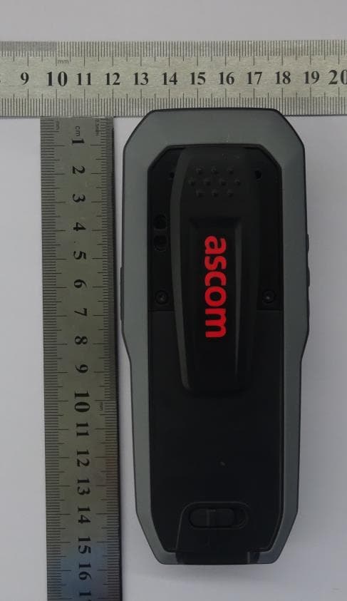
BXZDH8
Aug 09, 2021DECT Handset with Bluetooth and BLE
Equipment Class
JAB - Part 15 Class B Digital Device