BXZNILFLF Beacon
Ascom (Sweden) AB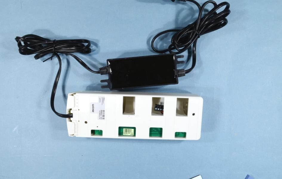
Click to zoom
Application Details
- Equipment Class
- DCD - Part 15 Low Power Transmitter Below 1705 kHz
- Date of Grant
- May 21, 2014
- Application Purpose
- Original Equipment
- Date of Application
- May 19, 2014
- Equipment Note
- LF Beacon
- Frequency Range
- 0.12500000 - 0.12500000
- Company
- Ascom (Sweden) AB
- Country
- Sweden
Documents & Files
Document Text
Text extracted from the exhibit documents filed with the FCC. Open a document above to read the original.
Users Manual
TD 93021US Rev A 10 FEB 2014 / Ver A Installation Guide teleCARE IP Emergency Call System TD 93021US Rev A 10 FEB 2014 / Ver Ai Installation Guide teleCARE IP Copyright © 2014 Ascom (US), Inc. This document may not be copied in whole or in part or otherwise reproduced without prior written consent from Ascom, except where specifically permitted under US and international copyright law. Disclaimer The information in this document is subject to change. Use this product only in accordance with the instructions provided in the installation and user guide manuals. Use this product only in accordance with the purposes for which it is designed. For the latest version of all Ascom teleCARE documentation, contact your local supplier or visit the Ascom Partner Website at https://www.ascom-ws.com . Trademarks and patents The teleCARE name and logo are trademarks of Ascom. Other trade names used in this document may be trademarks or registered trademarks of the manufacturers or vendors of the respective products. This publication may contain examples of screen captures and reports used in daily operations. Examples may include fictitious names of individuals and companies. Any similarity to names and addresses of actual businesses or per- sons is entirely coincidental. HIPAA disclaimer All examples of personal or protected health information in this document are fictitious. Any resemblance to a real person or facility is purely coincidental. The owners and users of this product are solely responsible for complying with all applicable protected health information privacy laws. The users, by their use of this product, agree to indemnify the manufacturer or seller of this product against all claims, litigation, and suits filed for protected health informa- tion violations. European Union directives The European directive “Waste Electrical and Electronic Equipment” (WEEE) aims to minimize the impact of electrical and electronic equipment waste on the environment and human health. To conform to this directive, electrical equipment marked with this symbol must not be disposed of in European public disposal systems. European users of electrical equipment must now return end-of-life equipment for disposal. Further information may be found on the fol- lowing website: www.recyclethis.info . Battery Disposal This product may use sealed lead-acid batteries. Please refer to manufacturer instructions and all state, provincial, and local codes for information, instructions and requirements regarding proper disposal. Environmental Requirements ·Refer to the installation guide and product data sheet for complete product ratings and information. ·Avoid exposing the device to direct sunlight or other heat sources. ·Do not expose the device to open flame. ·Keep the device away from excessive heat and moisture. ·Protect your device from aggressive liquids and vapors. ·Keep the device away from strong electromagnetic fields. Terms used in this manual Specialized terms are used throughout this manual. The first time a term is used it is defined in the text. Regulatory Compliance (EU/EFTA) This equipment is intended to be used in the whole EU & EFTA. This equipment is in compliance with the essential requirements and other relevant provisions of EMC Directive 2004/108/EC and RoHS Directive 2011/65/EU. For NIRX/NITX/NILF/NICR/NIRD products: R&TTE Directive 1999/5/EC and RoHS Directive 2011/65/EU. The Declaration of Conformity may be consulted at: http://www.ascom-ws.com/doc/ TD 93021US Rev A 10 FEB 2014 / Ver Aii Installation Guide teleCARE IP Regulatory Compliance (US/CAN) Safety Compliance The equipment described herein complies with: ·ANSI/UL 2560 Emergency Call Systems for Assisted Living and Independent Living Facilities ·CAN/CSA C22.2 No. 205 Signal Equipment Note: This equipment has been tested and found to comply with the limits for a Class B digi- tal device, pursuant to Part 15 of the FCC Rules. These limits are designed to provide reason- able protection against harmful interference in a residential installation. This equipment generates, uses, and can radiate radio frequency energy and, if not installed and used in accordance with the instructions, may cause harmful interference to radio communications. However, there is no guarantee that interference will not occur in a particular installation. If this equipment does cause harmful interference to radio or television reception, which can be determined by turning the equipment off and on, the user is encouraged to try to correct the interference by one or more of the following measures: ·Reorient or relocate the receiving antenna. ·Increase the separation between the equipment and receiver. ·Connect the equipment into an outlet on a circuit different from that to which the receiver is connected. ·Consult the dealer or an experienced radio or television technician for help. Information to user This device complies with Part 15 of the FCC Rules. Operation is subject to the following two conditions: i) this device may not cause harmful interference, and ii) this device must accept any interference received, including interference that may cause undesired operation. This device complies with Industry Canada license-exempt RSS standard(s). Operation is sub- ject to the following two conditions: (1) this device may not cause interference, and (2) this device must accept any interference, including interference that may cause undesired opera- tion of the device. Le présent appareil est conforme aux CNR d'Industrie Canada applicables aux appareils radio exempts de licence. L'exploitation est autorisée aux deux conditions suivantes: (1) l'appareil ne doit pas produire de brouillage, et (2) l'utilisateur de l'appareil doit accepter tout brouillage radioélectrique subi, même si le brouillage est susceptible d'en compromettre le fonctionnement. CAN ICES-3 (B)/NMB-3(B) Modifications Changes or modifications to the equipment not expressly approved by the party responsible for …
Text truncated - open the document above for the full version.
Users Manual
TD 93021US Rev A 10 FEB 2014 / Ver A26 Installation Guide teleCARE IP 5.2.10 Mounting the Housing without a Back box The housing can be mounted on a flat surface, without a back box, using four suitable screws in the outer fixing holes, as shown in the illustration below. When the NIRC housing is without a back box the cables should enter and leave the housing through the two knock-outs in the sides of the housing. Figure 20. Mounting the NIRC housing without a back box Caution: Do not distort the NIRC housing when it is mounted with or without a back box. To prevent distortion only mount the NIRC housing on a smooth, level surface and do not over- tighten the fixing screws! If the housing is distorted the top section will not fit properly and could fall off. 5.3Preparing the Room Bus and Power Cables It is important to prepare the cables appropriately and to guide the wires correctly inside the housing in order to avoid the wires pressing on the printed circuit board which could result in damage and also prevent the top section from closing properly. The following instructions apply to the room bus cables, the power supply cable and the corridor lamp cables. 5.3.1 Stripping the Outer Jacket of the Cables The first step is to strip the outer jacket of the cables to a length of 6.0in (150mm), then position the cable in the back box so that only the stripped wires enter the NIRC housing. Cable TD 93021US Rev A 10 FEB 2014 / Ver A27 Installation Guide teleCARE IP Figure 21. Stripping and positioning the cables for the NIRC Caution: Each room bus requires four wires. If the cable contains more than four wires the excess wires should be carefully stowed in the back box, away from the printed circuit board and other components to avoid electrical faults and safety problems. Details of the room bus connections are given in 5.4.1, 4-Pole Connector Terminal (NICT-4AA), page 31. Details of the 24Vdc power supply and corridor lamp connections are given in 5.4.2, 2-Pole Connector Terminal (NICT-2BA), page 33. Note: The 4-pole and the 2-pole connector terminals required for the room bus and the 24V power supply are not supplied with the IP room controller. The connectors are available as accessories and must be ordered separately. Details of for connecting the LED lamp boards are given in section 5.6, LED Lamp Boards, page 43. TD 93021US Rev A 10 FEB 2014 / Ver A28 Installation Guide teleCARE IP 5.3.2 Room Controller PCB Connections (NIRC-GMS and NIRC-WMS with Speech) The electrical connections on the component side of the IP room controller printed circuit board are shown in the following drawing of the NIRC circuit board. Figure 22. IP room controller (with speech) PCB electrical connections Details of the room bus connections are given in 5.4.1, 4-Pole Connector Terminal (NICT-4AA), page 31. Details of the 24Vdc power supply and corridor lamp connections are given in 5.4.2, 2-Pole Connector Terminal (NICT-2BA), page 33 Note: The 6-pole, 4-pole and the 2-pole connector terminals required for the external corridor LED lamps, the room bus and the 24V power supply are not supplied with the IP room controller. The connectors are available as accessories and must be ordered separately. Details of for connecting the LED lamp boards are given in section 5.6, LED Lamp Boards, page 43. Details of for connecting external corridor lamp LEDs are given in section 5.6.4, External Corridor Lamp Connections, page 47 PoE Extension Connector (Future use) LED Lamp Board Through-Board Connectors (only applicable to corridor lamp version) Room Bus 2Room Bus 1Room Bus 0 RJ 45 LAN Connector Note: The 24Vdc power outputs are only to be used for the corridor lamps! Buzzer External Corridor Lamp Outputs (Max. load per connection: 60mA) 2 x 24Vdc OUT Corridor Lamps Power Supply. 24Vdc IN Room Controller Power Supply Note: The combined load of the three room buses must not exceed 750mA! TD 93021US Rev A 10 FEB 2014 / Ver A29 Installation Guide teleCARE IP 5.3.3 IP Room Controller (NIRC) Printed Circuit Board Back View Figure 23. NIRC printed circuit board back view On the back of the printed circuit board there are four sets of through-board connection holes for LED lamp boards. Details of for connecting the LED lamp boards are given in section 5.6, LED Lamp Boards, page 43. Also on the back of the IP room controller printed circuit board there is a set of three identical MAC address labels and a product label which includes the part number and serial number. The three MAC labels are self-adhesive and can be removed from the printed circuit board. One of the labels should be left on the room controller printed circuit board. The other two can be removed and one can be stuck on the cover of the room controller, so the board can be identified without opening the room controller. The other can be used in a list of all room controller locations, for example, for administration purposes. Product label with part number and serial number Through-Board Connection Holes for the LED Lamp MAC address label TD 93021US Rev A 10 FEB 2014 / Ver A30 Installation Guide teleCARE IP 5.3.4 Room Controller (NIRC3) PCB Connections The electrical connections on the component side of the room controller printed circuit board are shown in the following drawing of the NIRC3 circuit board. Figure 24. Room controller (NIRC3) PCB electrical connections Details of the room bus connections are given in 5.4.1, 4-Pole Connector Terminal (NICT-4AA), page 31. The NIRC3 can be powered directly from a Power over Ethernet (PoE 802.3af or 802.3at) switch or through an external 24V DC power supply. Details of the 24V DC power supply connections are given in 5.4.2, 2-Pole Connector Terminal (NICT-2BA), page 33 The NIRC3 has two USB2.0HS host ports. Will be used in a future release to support WiFi functionality. Note: The 4-pole and the 2-pole connector terminals required for the room bus and the 24V power supply are not supplied with the room controller. The connect…
Text truncated - open the document above for the full version.
Users Manual
TD 93021US Rev A 10 FEB 2014 / Ver A46 Installation Guide teleCARE IP 5.6.3 Installing the LED Lamp Boards on the IP Room Controller Board On the back side of the IP room controller PCB there are the four sets of through-board connections for the LED lamp boards. Each through-board connector has three holes which accept the three connecting pins on the LED lamp board. Figure 50. LED through-board connectors and guide marks The LED lamp connection points are labeled LED0, LED1, LED2 and LED3. Any color LED board can be plugged into any of the connection points in the IP room controller. The appropriate position of the LED color is determined during the system setup. Caution: The pins on the LED lamp board are not in the center of the board so it is important to make sure that the LED lamp board lines up with the guide marks on the IP room controller PCB when the pins are inserted. Figure 51. Plugging LED lamp board into the room controller PCB With the three pins inserted and the LED lamp board lined up with the guide marks, firmly press the LED lamp board into the IP room controller PCB. Repeat the procedure on the other required LED lamp LED Lamp Board Guide Marks Through-Board Connection Holes for the LED Lamp Boards Insert the pins of the LED lamp board in the holes in the Room Controller PCB Align the LED Lamp Board with the Guide Marks on the Room Controller PCB TD 93021US Rev A 10 FEB 2014 / Ver A47 Installation Guide teleCARE IP boards. Figure 52. NIRC room controller PCB with 4 LED lamp boards Example of the second generation LED lamp boards (NILD2) mounted on the NIRC3. Figure 53. NIRC3- room controller PCB with 4 LED lamp boards 5.6.4 External Corridor Lamp Connections The NIRC has a 6-pole connector for connection of an external corridor lamp with up to four separate LEDs. NIRC3 TD 93021US Rev A 10 FEB 2014 / Ver A48 Installation Guide teleCARE IP The outputs L1, L2, L3 and L4 are parallel circuits to LED connections on the NIRC printed circuit board. Each external LED must be connected between the lamp connector (L1, L2, L3 or L4) and +V on the 6-pole connector. Figure 54. External corridor lamp connections of the NIRC Caution: The maximum load on each external LED circuit is 60mA. IMPORTANT: The maximum load on each external LED circuit is 60mA. The room controller (NIRC3) circuit board does not support an external corridor lamp directly, however an external lamp can be connected through a green LED lamp board (NILD2-GAA) which has a galvanically separated output with a maximum switching capacity of 0.4A at 60V peak. Figure 55. External corridor lamp connections through the NILD2-GAA See “Auxiliary Lamp Connection - NILD2” on page 52. for detailed information. NIRC3 To auxiliary power supply Max. 0.4A at 60V peak IMPORTANT: In order to retain the galvanic separation, it is not allowed to connect the GND (-) of the auxiliary power supply to the GND (-) of the NIRC3. TD 93021US Rev A 10 FEB 2014 / Ver A49 Installation Guide teleCARE IP 5.7Corridor Lamp (NICL) The Corridor Lamp (NICL) is controlled by the IP room controller (NIRC only) and one IP room controller can support two corridor lamps. Each Corridor Lamp is connected to one of the three room buses of the IP Room Controller and it always has the fixed address 5. IMPORTANT: The room controller NIRC3 does not support the 24 volt output that is required to power the NICL, therefore the NICL should not be used in combination with the NIRC3. Figure 56. The teleCARE IP corridor lamp The Corridor Lamp consists of a back box, a printed circuit module, a cover plate and translucent dome cover that can accept up to four LED boards, as shown in the following illustration: TD 93021US Rev A 10 FEB 2014 / Ver A50 Installation Guide teleCARE IP Figure 57. Corridor lamp (NICL) parts 5.7.1 Installing the Corridor Lamp When installing the Corridor Lamp the first step is to separate the top section (cover, PC board and lamp dome) from the housing. To do that simply grip the top edge of the cover and pull it away from the housing, as shown in the following illustration: Figure 58. Separating the top section from the housing TD 93021US Rev A 10 FEB 2014 / Ver A51 Installation Guide teleCARE IP 5.7.2 Removing the Corridor Lamp Printed Circuit Board To remove the circuit board from the housing, press the holding clip outwards until it releases the circuit board, as shown in the following illustration: Figure 59. Removing the circuit board from the housing With the printed circuit board released from the holding clip, partly rotate the circuit board and remove it from the housing. 5.7.3 Corridor Lamp Housing The corridor lamp has the same housing as used for the IP room controller which is designed to be surface mounted. Refer to section 5.2.8, Room Controller Housing on page 24 for details of mounting TD 93021US Rev A 10 FEB 2014 / Ver A52 Installation Guide teleCARE IP the housing. Figure 60. IP room controller housing 5.7.4 Corridor Lamp Electrical Connections The wiring between NIRC Room Controller and the NICL Corridor Lamp consists of the teleCARE IP four-wire room bus plus two additional wires for 24Vdc to power the corridor lamp LEDs. Figure 61. Corridor lamp PCB component side electrical connections LED Lamp Through-Board Connectors 24Vdc Power Supply (from the Room Controller) Room Bus (from the Room Controller) Buzzer Connectors for External LED inputs/outputs TD 93021US Rev A 10 FEB 2014 / Ver A53 Installation Guide teleCARE IP 5.7.5 4-Pole Connector Terminal Figure 62. 4-pole connector terminal The 4-pole connector terminal is used for connecting the room bus. It has a screw-less “spring-cage” connection technique and each terminal has two connection points. The designation of the required four wires is as shown in the following illustration. Figure 63. 4-pole connector terminal with the room bus Preparing the wires and connecting the 4-pole connection terminal is described in section 5.4.1, 4- Pole Connector Terminal (NICT-4AA) on…
Text truncated - open the document above for the full version.
Users Manual
TD 93021US Rev A 10 FEB 2014 / Ver A86 Installation Guide teleCARE IP The Passive Pull Cord Module is intended for use in the teleCARE IP system, in areas such as bath- rooms and toilets. It must be connected to the passive bus of a door side module or active pull cord cancel module. When connected to the door side module, it can be combined with the passive toilet cancel module on the same passive bus. The passive bus consists of four wires (see 6.4.1, 4-Pole Connector Terminal on page 65). For assembly and attaching instructions for the pull cord refer to 6.8.2, Assembling and Attaching the Pull Cord on page 84. The Passive Pull Cord Module requires a single backplate which must be ordered separately. The backplate enables this switch module to be mounted over different types of back boxes. Alternatively, a spacer with installation kit is available for surface mounting. 6.10.1 Pull Cord Module (Passive) Electrical Connections The passive pull cord module is a “passive peripheral” therefore it must be connected to the passive bus of the linked door side module or active pull cord module by the 4-pole passive bus connector (see 6.4.1, 4-Pole Connector Terminal on page 65). Figure 108. Passive pull cord module electrical connections 6.11 Toilet Cancel Module - Passive (NITC-XXP) Figure 109. Passive toilet cancel module The Passive Toilet Cancel Module is intended for use in the teleCARE IP system, in areas such as bathrooms and toilets. It must be connected to the passive bus of a door side module or a room display module. 4-Pole Connector for the Passive Bus TD 93021US Rev A 10 FEB 2014 / Ver A87 Installation Guide teleCARE IP IMPORTANT: Together with the passive toilet cancel module a passive pull cord module which contains the line break detection circuitry must be installed. The passive pull cord module must be connected at the end of the passive bus. The Passive Toilet Cancel Module requires a single backplate which must be ordered separately. The backplate enables this switch module to be mounted over different types of back boxes. Alternatively, a spacer with installation kit is available for surface mounting the switch module. 6.11.1 Passive Toilet Cancel Module (Passive) Electrical Connections This toilet cancel module is a “passive peripheral” therefore it must be connected to the passive bus of the linked door side module by the 4-pole passive bus connector (see 6.4.1, 4-Pole Connector Terminal on page 65). Figure 110. Passive toilet cancel module electrical connections Note: The 4-pole connector terminal for the passive bus is not supplied with the switch module. It is available as an accessory and must be ordered separately. 6.12 Pull Cord Module (NIPC2) Active and Passive The NIPC2 Pull Cord Modules are designed for use in the teleCARE IP system. They are IP44 splash proof and therefore suitable for use in rooms with showers, baths and in similar wet areas. They are available as an “active” module and a “passive” module. 4-Pole Connector for the Passive Bus TD 93021US Rev A 10 FEB 2014 / Ver A88 Installation Guide teleCARE IP The NIPC2 is available in gray or white and has a pull cord of length 2 meter with two plastic balls. The top ball acts as a safety break by splitting in half when the cord is pulled with excessive force. Figure 111. NIPC2 Pull cord module (exploded/assembled) The active version of the NIPC2 is connected to one of the room buses of the IP Room Controller. It has a 4-pin connector for the connection of the room bus, consisting of: 5.5Vdc, data, voice and ground (0V). The room bus address is set by DIP switches. The passive version must be connected to the passive bus of a door side module, a room display or a toilet cancel module. It has a 4-pin connector for the connection of the passive bus, consisting of: 5.5Vdc, Aux-In0, Aux-In1 and Aux-out. Note: The 4-pole connector terminal required for the room bus is not supplied with the switch module. It is available as an accessory and must be ordered separately. The NIPC2 Pull Cord Module includes a special backplate with two urethane foam gaskets which makes the NIPC2 splash water resistant to IP44 standard. The backplate must be mounted on a flat wall surface using the four corner holes in the backplate. The module is fixed on to the backplate by two latches and two screws through the cover plate. The screws are supplied with the module. WARNING:The NIPC2 can only be mounted on the supplied IP44 backplate. It is not compatible with the standard teleCARE switch module backplate and it is not compatible with the teleCARE surface mounting spacer. 6.12.1 Mounting the NIPC2 Pull Cord Module In order to avoid physical damage to the module and to reduce the risk of exposure to excessive spray water in shower rooms, bathrooms and similar wet areas, the NIPC2 should be installed with the pull cord module mounted above the height of any water source. The NIPC2 should be mounted in a location which ensures that the pull cord hangs free of any obstructions, is clearly seen and within easy reach so that it can be pulled to activate a call by residents or staff in an emergency or when assistance is required. TD 93021US Rev A 10 FEB 2014 / Ver A89 Installation Guide teleCARE IP The NIPC2 should be mounted at a minimum height of 90.5in (2300mm) above the floor and at least 8in (200mm) above the highest position of the shower head. Where possible the pull cord should extend down to approximately 9in (200mm) above the floor. The following illustration shows some examples of suitable locations for the pull cord module. Figure 112. Examples of suitable locations for mounting the NIPC2 6.12.2 Positioning the Back box for the Pull Cord Module The NIPC2 pull cord module must be mounted on a smooth flat surface in order to ensure that it is splash water proof in accordance with IP44. The ideal surface is a ceramic tiled wall with the back box for the NIPC2 situated in the center of a tile so that the pull cord module backplate do…
Text truncated - open the document above for the full version.
Users Manual
TD 93021US Rev A 10 FEB 2014 / Ver A116 Installation Guide teleCARE IP 6.18.1 Sunblind Motor Controller Figure 155. Sunblind control module electrical connections The sunblind control module can be connected to one room bus and will only respond to room bus addresses 0 to 3 of the connected room bus. The Room Bus “a” DIP switches are used to prevent the sunblind control module from responding to specific room bus addresses. Setting a DIP switch to the ON position selects that particular address, 0 to 3 to control the module. WARNING:Up to 230Vac power to the sunblind motor control relay must be fused at 2 Amps. Appropriate cable for the voltage and current must be used for the sunblind motor control. WARNING:The equipment that is connected to this interface is not considered to be part of the teleCARE IP system. 1 2 3 4 ON 1 2 3 4 ON Room Controller Room Bus “a” + 5.5vdc GND DATA + 5.5vdc GND DATA b DATA a COM DOWN UP Address Isolation DIP Switch Room Bus “a” 01 2 3 Sunblind Motor (Max. 2A) 2A TD 93021US Rev A 10 FEB 2014 / Ver A117 Installation Guide teleCARE IP 7Corridor Equipment 7.1Corridor Display (NICD) The NICD is a supplemental IP based corridor display suitable for use in teleCARE IP, and contains a LAN interface for connection to the teleCARE IP LAN network. The NICD has a large character, 3-color (Red/Green/Amber) message display and a signaling buzzer. It is available as a single or double sided unit with a 6-character or a 12-character display. Figure 159. 6 and 12 character Corridor Display (NICD) WARNING:The NICD equipment described in this section is for supplementary purposes only, is not evaluated to UL 2560 and is not part of the teleCARE IP system UL listing. From the built-in web interface the basic configuration of the NICD can be adjusted, for example the IP address, host name and communication port. General text display settings can be set in the NISM2. Up to 50 NICDs can be added to a single NISM2. The NISM2 is used to define such things as message display time, number of stored messages, the color of the displayed message depending on message priority and buzzer options. The NICD display mode can be constant or scrolling. The display mode can be set to constant (with short blank period in between) or to scrolling (from bottom to top) when there are two or more active calls to be displayed. The NICD can display up to 30 different messages. If the maximum number of messages is reached, the oldest message with the lowest priority will be cleared first. When the display is not showing any messages (idle), it can be configured to show the time/date or any other type of welcome message. 7.1.1 Corridor Display Network Requirements - Ethernet 10 BaseT - half duplex - no auto-crossing - no auto-negotiation - no auto-polarity Note: The display will not work on non-standard (reversed polarity) switches using a normal straight cable. Reversed polarity switches require a special Reverse Polarity Cable. TD 93021US Rev A 10 FEB 2014 / Ver A118 Installation Guide teleCARE IP 7.1.2 Preparing Single-Sided Displays Prior to Mounting Before a single-sided display can be mounted, the LAN cable must be connected to the rear of the display first. The first step is to remove the metal strain reliever plate from the back of the display by unscrewing the 2 screws. Figure 160. Remove the strain reliever plate Plug the RJ-45 connector of the network cable into the ethernet socket of the display and place the strain reliever plate back in place. Figure 161. Plug in the RJ-45 connector TD 93021US Rev A 10 FEB 2014 / Ver A119 Installation Guide teleCARE IP 7.1.3 Mounting the Corridor Display The NICD is prepared for wall mounting using a special wall mounting bracket which is available as an accessory. Figure 162. Wall mounted NICD NICD Wall Mounting Bracket The NICD wall mounting bracket is available in two sizes, for the 6-character display and for the 12- character display. Figure 163. 6 and 12 character mounting brackets Dimensions & Weights The method used to fix the mounting bracket to the wall must be capable of safely supporting the combined weight of the NICD and the mounting bracket. 6 Character NICD • Weight of the 6 character single-sided display = 3.7 pounds/1.7 kg • Weight of the 6 character double-sided display = 4.4 pounds/2 kg • Weight of the 6 character mounting bracket = 3.3 pounds/1.5 kg TD 93021US Rev A 10 FEB 2014 / Ver A120 Installation Guide teleCARE IP 12 Character NICD • Weight of the 12 character single-sided display = 6.2 pounds/2.8 kg • Weight of the 12 character double-sided display = 7.3 pounds/3.3 kg • Weight of the 12 character mounting bracket = 4.4 pounds/2 kg TD 93021US Rev A 10 FEB 2014 / Ver A121 Installation Guide teleCARE IP When placing the wall mounting bracket on the wall, consider the minimum height at which the display should be mounted. The minimum installation height depends on things like opening a door in the vicinity of a display or an object transported through the corridor. Make sure that in none of these circumstances the object will hit the display. Figure 164. Minimum installation height To mount the bracket on the wall, drill four holes according to the dimensions of the 6 or 12 character mounting bracket. 3 1/3 in. () 3 1/2 in. () 21 in. () 27 1/2 in. ( ) 21 in. () 2 3/8 in. () 25 3/4 in. (655 mm) 3 in. (76 mm) 1 1/2 in. (38 mm) 2 3/8 in. ( ) 5/8 in. ( ) 1 in.(25 mm) 9 1/2 in. 11 in. (( ) ) TD 93021US Rev A 10 FEB 2014 / Ver A122 Installation Guide teleCARE IP Figure 165. Drilling four holes for mounting the bracket Fix the mounting bracket on the wall by using four well-fitted screws capable of carrying the weight of both the display and the mounting bracket. Figure 166. Fixing the wall mounting bracket The next step is to mount the display on the wall mounting bracket. First start by removing the two hex screws at the top of the display using an allen key (Hex key wrench). Figure 167. Use the included accessories to mount the display …
Text truncated - open the document above for the full version.
Contact Information
Applicant
Peter Soderberg
Test Firm
Nemko ASFrode Sveinsen
Technical Specifications
| # | Rule Parts | Frequency Range | Power Output |
|---|---|---|---|
| 1 | 15C | 0.125 MHz - 0.125 MHz | - |
Other Applications from Ascom (Sweden) AB

BXZCHAT2
Sep 27, 2023Narrow band alarm transceiver
Equipment Class
TNB - Licensed Non-Broadcast Station Transmitter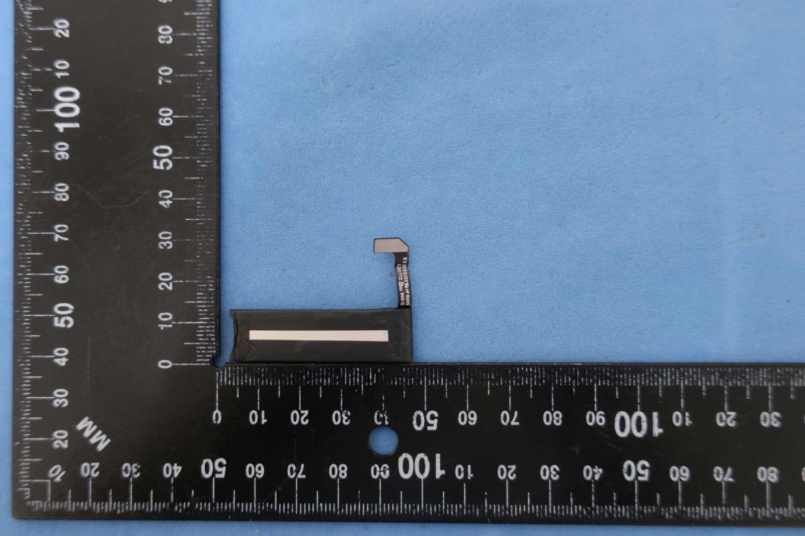
BXZSH4
Aug 02, 2023Myco 4 WiFi, Myco 4 Slim
Equipment Class
JBP - Part 15 Class B Computing Device Peripheral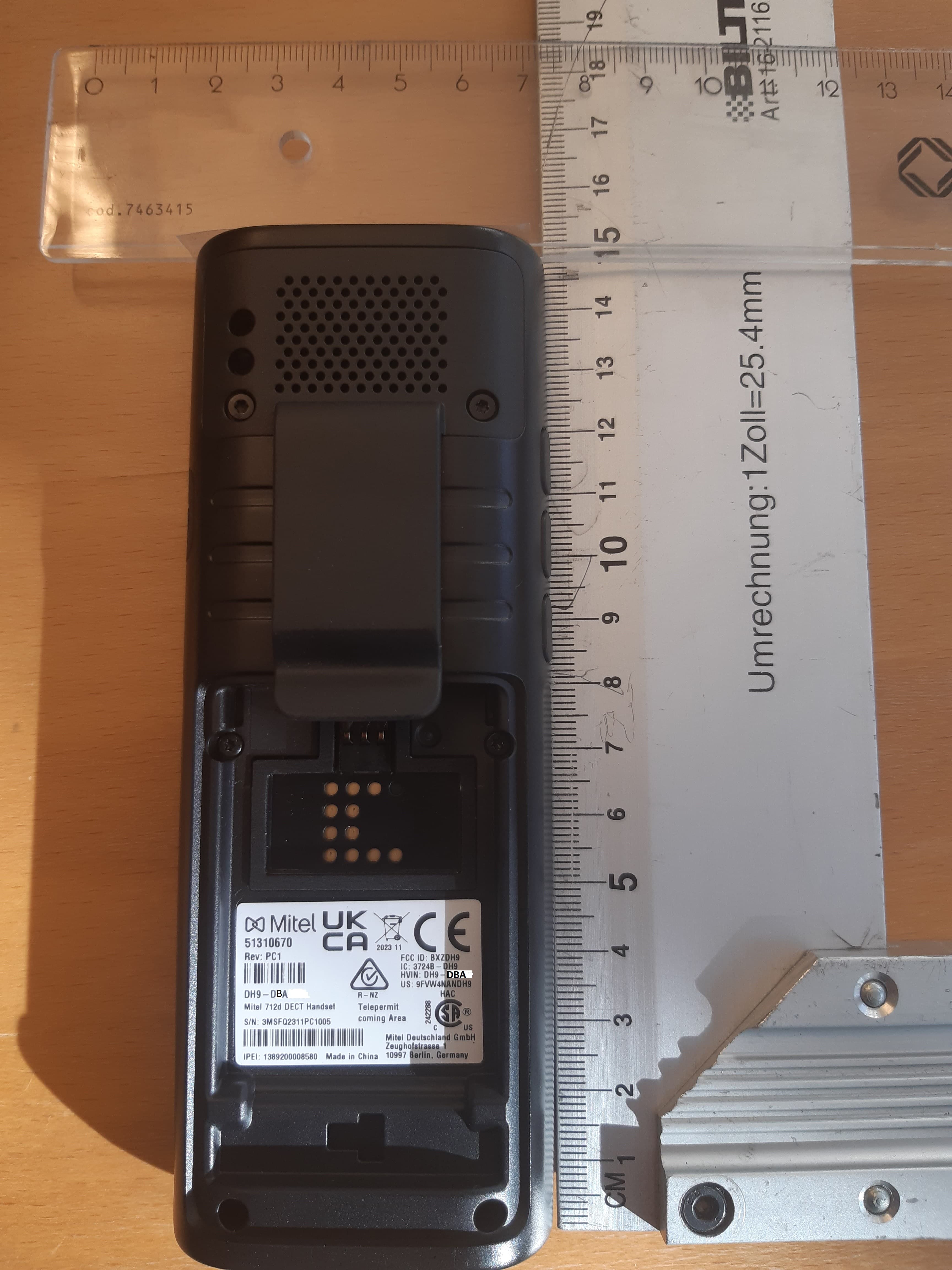
BXZDH9
Apr 16, 2023DECT Handset with Bluetooth
Equipment Class
PUE - Part 15 Unlicensed PCS portable Tx held to ear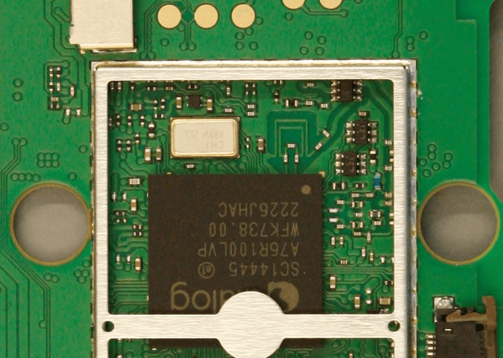
BXZDH10
Apr 16, 2023DECT Handset with Bluetooth
Equipment Class
DSS - Part 15 Spread Spectrum Transmitter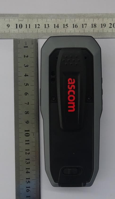
BXZDH8
Aug 09, 2021DECT Handset with Bluetooth and BLE
Equipment Class
JAB - Part 15 Class B Digital Device