BXZNITXNITX-AAB Mobile Tx teleCARE IP NA, NITX-BAB Mobile Tx teleCARE IP_LF, NA, NITX-BBB Staff transceiver, NA
Ascom (Sweden) AB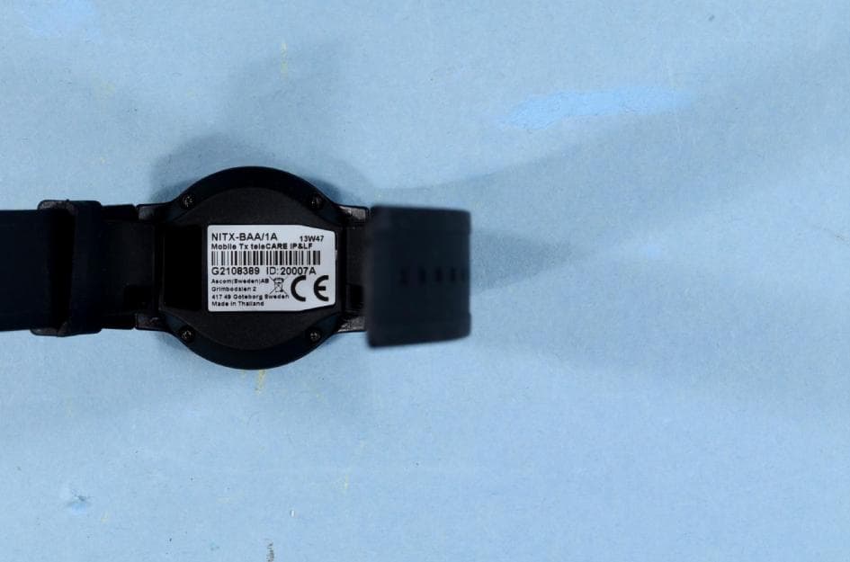
Click to zoom
Application Details
- Equipment Class
- DXT - Part 15 Low Power Transceiver, Rx Verified
- Date of Grant
- May 26, 2014
- Application Purpose
- Original Equipment
- Date of Application
- May 26, 2014
- Equipment Note
- NITX-AAB Mobile Tx teleCARE IP NA, NITX-BAB Mobile Tx teleCARE IP_LF, NA, NITX-BBB Staff transceiver, NA
- Frequency Range
- 916.21250000 - 920.21250000
- Company
- Ascom (Sweden) AB
- Country
- Sweden
Documents & Files
Document Text
Text extracted from the exhibit documents filed with the FCC. Open a document above to read the original.
Users Manual
TD 93021US Rev A 10 FEB 2014 / Ver A Installation Guide teleCARE IP Emergency Call System TD 93021US Rev A 10 FEB 2014 / Ver Ai Installation Guide teleCARE IP Copyright © 2014 Ascom (US), Inc. This document may not be copied in whole or in part or otherwise reproduced without prior written consent from Ascom, except where specifically permitted under US and international copyright law. Disclaimer The information in this document is subject to change. Use this product only in accordance with the instructions provided in the installation and user guide manuals. Use this product only in accordance with the purposes for which it is designed. For the latest version of all Ascom teleCARE documentation, contact your local supplier or visit the Ascom Partner Website at https://www.ascom-ws.com . Trademarks and patents The teleCARE name and logo are trademarks of Ascom. Other trade names used in this document may be trademarks or registered trademarks of the manufacturers or vendors of the respective products. This publication may contain examples of screen captures and reports used in daily operations. Examples may include fictitious names of individuals and companies. Any similarity to names and addresses of actual businesses or per- sons is entirely coincidental. HIPAA disclaimer All examples of personal or protected health information in this document are fictitious. Any resemblance to a real person or facility is purely coincidental. The owners and users of this product are solely responsible for complying with all applicable protected health information privacy laws. The users, by their use of this product, agree to indemnify the manufacturer or seller of this product against all claims, litigation, and suits filed for protected health informa- tion violations. European Union directives The European directive “Waste Electrical and Electronic Equipment” (WEEE) aims to minimize the impact of electrical and electronic equipment waste on the environment and human health. To conform to this directive, electrical equipment marked with this symbol must not be disposed of in European public disposal systems. European users of electrical equipment must now return end-of-life equipment for disposal. Further information may be found on the fol- lowing website: www.recyclethis.info . Battery Disposal This product may use sealed lead-acid batteries. Please refer to manufacturer instructions and all state, provincial, and local codes for information, instructions and requirements regarding proper disposal. Environmental Requirements ·Refer to the installation guide and product data sheet for complete product ratings and information. ·Avoid exposing the device to direct sunlight or other heat sources. ·Do not expose the device to open flame. ·Keep the device away from excessive heat and moisture. ·Protect your device from aggressive liquids and vapors. ·Keep the device away from strong electromagnetic fields. Terms used in this manual Specialized terms are used throughout this manual. The first time a term is used it is defined in the text. Regulatory Compliance (EU/EFTA) This equipment is intended to be used in the whole EU & EFTA. This equipment is in compliance with the essential requirements and other relevant provisions of EMC Directive 2004/108/EC and RoHS Directive 2011/65/EU. For NIRX/NITX/NILF/NICR/NIRD products: R&TTE Directive 1999/5/EC and RoHS Directive 2011/65/EU. The Declaration of Conformity may be consulted at: http://www.ascom-ws.com/doc/ TD 93021US Rev A 10 FEB 2014 / Ver Aii Installation Guide teleCARE IP Regulatory Compliance (US/CAN) Safety Compliance The equipment described herein complies with: ·ANSI/UL 2560 Emergency Call Systems for Assisted Living and Independent Living Facilities ·CAN/CSA C22.2 No. 205 Signal Equipment Note: This equipment has been tested and found to comply with the limits for a Class B digi- tal device, pursuant to Part 15 of the FCC Rules. These limits are designed to provide reason- able protection against harmful interference in a residential installation. This equipment generates, uses, and can radiate radio frequency energy and, if not installed and used in accordance with the instructions, may cause harmful interference to radio communications. However, there is no guarantee that interference will not occur in a particular installation. If this equipment does cause harmful interference to radio or television reception, which can be determined by turning the equipment off and on, the user is encouraged to try to correct the interference by one or more of the following measures: ·Reorient or relocate the receiving antenna. ·Increase the separation between the equipment and receiver. ·Connect the equipment into an outlet on a circuit different from that to which the receiver is connected. ·Consult the dealer or an experienced radio or television technician for help. Information to user This device complies with Part 15 of the FCC Rules. Operation is subject to the following two conditions: i) this device may not cause harmful interference, and ii) this device must accept any interference received, including interference that may cause undesired operation. This device complies with Industry Canada license-exempt RSS standard(s). Operation is sub- ject to the following two conditions: (1) this device may not cause interference, and (2) this device must accept any interference, including interference that may cause undesired opera- tion of the device. Le présent appareil est conforme aux CNR d'Industrie Canada applicables aux appareils radio exempts de licence. L'exploitation est autorisée aux deux conditions suivantes: (1) l'appareil ne doit pas produire de brouillage, et (2) l'utilisateur de l'appareil doit accepter tout brouillage radioélectrique subi, même si le brouillage est susceptible d'en compromettre le fonctionnement. CAN ICES-3 (B)/NMB-3(B) Modifications Changes or modifications to the equipment not expressly approved by the party responsible for …
Text truncated - open the document above for the full version.
Users Manual
TD 93021US Rev A 10 FEB 2014 / Ver A26 Installation Guide teleCARE IP 5.2.10 Mounting the Housing without a Back box The housing can be mounted on a flat surface, without a back box, using four suitable screws in the outer fixing holes, as shown in the illustration below. When the NIRC housing is without a back box the cables should enter and leave the housing through the two knock-outs in the sides of the housing. Figure 20. Mounting the NIRC housing without a back box Caution: Do not distort the NIRC housing when it is mounted with or without a back box. To prevent distortion only mount the NIRC housing on a smooth, level surface and do not over- tighten the fixing screws! If the housing is distorted the top section will not fit properly and could fall off. 5.3Preparing the Room Bus and Power Cables It is important to prepare the cables appropriately and to guide the wires correctly inside the housing in order to avoid the wires pressing on the printed circuit board which could result in damage and also prevent the top section from closing properly. The following instructions apply to the room bus cables, the power supply cable and the corridor lamp cables. 5.3.1 Stripping the Outer Jacket of the Cables The first step is to strip the outer jacket of the cables to a length of 6.0in (150mm), then position the cable in the back box so that only the stripped wires enter the NIRC housing. Cable TD 93021US Rev A 10 FEB 2014 / Ver A27 Installation Guide teleCARE IP Figure 21. Stripping and positioning the cables for the NIRC Caution: Each room bus requires four wires. If the cable contains more than four wires the excess wires should be carefully stowed in the back box, away from the printed circuit board and other components to avoid electrical faults and safety problems. Details of the room bus connections are given in 5.4.1, 4-Pole Connector Terminal (NICT-4AA), page 31. Details of the 24Vdc power supply and corridor lamp connections are given in 5.4.2, 2-Pole Connector Terminal (NICT-2BA), page 33. Note: The 4-pole and the 2-pole connector terminals required for the room bus and the 24V power supply are not supplied with the IP room controller. The connectors are available as accessories and must be ordered separately. Details of for connecting the LED lamp boards are given in section 5.6, LED Lamp Boards, page 43. TD 93021US Rev A 10 FEB 2014 / Ver A28 Installation Guide teleCARE IP 5.3.2 Room Controller PCB Connections (NIRC-GMS and NIRC-WMS with Speech) The electrical connections on the component side of the IP room controller printed circuit board are shown in the following drawing of the NIRC circuit board. Figure 22. IP room controller (with speech) PCB electrical connections Details of the room bus connections are given in 5.4.1, 4-Pole Connector Terminal (NICT-4AA), page 31. Details of the 24Vdc power supply and corridor lamp connections are given in 5.4.2, 2-Pole Connector Terminal (NICT-2BA), page 33 Note: The 6-pole, 4-pole and the 2-pole connector terminals required for the external corridor LED lamps, the room bus and the 24V power supply are not supplied with the IP room controller. The connectors are available as accessories and must be ordered separately. Details of for connecting the LED lamp boards are given in section 5.6, LED Lamp Boards, page 43. Details of for connecting external corridor lamp LEDs are given in section 5.6.4, External Corridor Lamp Connections, page 47 PoE Extension Connector (Future use) LED Lamp Board Through-Board Connectors (only applicable to corridor lamp version) Room Bus 2Room Bus 1Room Bus 0 RJ 45 LAN Connector Note: The 24Vdc power outputs are only to be used for the corridor lamps! Buzzer External Corridor Lamp Outputs (Max. load per connection: 60mA) 2 x 24Vdc OUT Corridor Lamps Power Supply. 24Vdc IN Room Controller Power Supply Note: The combined load of the three room buses must not exceed 750mA! TD 93021US Rev A 10 FEB 2014 / Ver A29 Installation Guide teleCARE IP 5.3.3 IP Room Controller (NIRC) Printed Circuit Board Back View Figure 23. NIRC printed circuit board back view On the back of the printed circuit board there are four sets of through-board connection holes for LED lamp boards. Details of for connecting the LED lamp boards are given in section 5.6, LED Lamp Boards, page 43. Also on the back of the IP room controller printed circuit board there is a set of three identical MAC address labels and a product label which includes the part number and serial number. The three MAC labels are self-adhesive and can be removed from the printed circuit board. One of the labels should be left on the room controller printed circuit board. The other two can be removed and one can be stuck on the cover of the room controller, so the board can be identified without opening the room controller. The other can be used in a list of all room controller locations, for example, for administration purposes. Product label with part number and serial number Through-Board Connection Holes for the LED Lamp MAC address label TD 93021US Rev A 10 FEB 2014 / Ver A30 Installation Guide teleCARE IP 5.3.4 Room Controller (NIRC3) PCB Connections The electrical connections on the component side of the room controller printed circuit board are shown in the following drawing of the NIRC3 circuit board. Figure 24. Room controller (NIRC3) PCB electrical connections Details of the room bus connections are given in 5.4.1, 4-Pole Connector Terminal (NICT-4AA), page 31. The NIRC3 can be powered directly from a Power over Ethernet (PoE 802.3af or 802.3at) switch or through an external 24V DC power supply. Details of the 24V DC power supply connections are given in 5.4.2, 2-Pole Connector Terminal (NICT-2BA), page 33 The NIRC3 has two USB2.0HS host ports. Will be used in a future release to support WiFi functionality. Note: The 4-pole and the 2-pole connector terminals required for the room bus and the 24V power supply are not supplied with the room controller. The connect…
Text truncated - open the document above for the full version.
Users Manual
TD 93021US Rev A 10 FEB 2014 / Ver A46 Installation Guide teleCARE IP 5.6.3 Installing the LED Lamp Boards on the IP Room Controller Board On the back side of the IP room controller PCB there are the four sets of through-board connections for the LED lamp boards. Each through-board connector has three holes which accept the three connecting pins on the LED lamp board. Figure 50. LED through-board connectors and guide marks The LED lamp connection points are labeled LED0, LED1, LED2 and LED3. Any color LED board can be plugged into any of the connection points in the IP room controller. The appropriate position of the LED color is determined during the system setup. Caution: The pins on the LED lamp board are not in the center of the board so it is important to make sure that the LED lamp board lines up with the guide marks on the IP room controller PCB when the pins are inserted. Figure 51. Plugging LED lamp board into the room controller PCB With the three pins inserted and the LED lamp board lined up with the guide marks, firmly press the LED lamp board into the IP room controller PCB. Repeat the procedure on the other required LED lamp LED Lamp Board Guide Marks Through-Board Connection Holes for the LED Lamp Boards Insert the pins of the LED lamp board in the holes in the Room Controller PCB Align the LED Lamp Board with the Guide Marks on the Room Controller PCB TD 93021US Rev A 10 FEB 2014 / Ver A47 Installation Guide teleCARE IP boards. Figure 52. NIRC room controller PCB with 4 LED lamp boards Example of the second generation LED lamp boards (NILD2) mounted on the NIRC3. Figure 53. NIRC3- room controller PCB with 4 LED lamp boards 5.6.4 External Corridor Lamp Connections The NIRC has a 6-pole connector for connection of an external corridor lamp with up to four separate LEDs. NIRC3 TD 93021US Rev A 10 FEB 2014 / Ver A48 Installation Guide teleCARE IP The outputs L1, L2, L3 and L4 are parallel circuits to LED connections on the NIRC printed circuit board. Each external LED must be connected between the lamp connector (L1, L2, L3 or L4) and +V on the 6-pole connector. Figure 54. External corridor lamp connections of the NIRC Caution: The maximum load on each external LED circuit is 60mA. IMPORTANT: The maximum load on each external LED circuit is 60mA. The room controller (NIRC3) circuit board does not support an external corridor lamp directly, however an external lamp can be connected through a green LED lamp board (NILD2-GAA) which has a galvanically separated output with a maximum switching capacity of 0.4A at 60V peak. Figure 55. External corridor lamp connections through the NILD2-GAA See “Auxiliary Lamp Connection - NILD2” on page 52. for detailed information. NIRC3 To auxiliary power supply Max. 0.4A at 60V peak IMPORTANT: In order to retain the galvanic separation, it is not allowed to connect the GND (-) of the auxiliary power supply to the GND (-) of the NIRC3. TD 93021US Rev A 10 FEB 2014 / Ver A49 Installation Guide teleCARE IP 5.7Corridor Lamp (NICL) The Corridor Lamp (NICL) is controlled by the IP room controller (NIRC only) and one IP room controller can support two corridor lamps. Each Corridor Lamp is connected to one of the three room buses of the IP Room Controller and it always has the fixed address 5. IMPORTANT: The room controller NIRC3 does not support the 24 volt output that is required to power the NICL, therefore the NICL should not be used in combination with the NIRC3. Figure 56. The teleCARE IP corridor lamp The Corridor Lamp consists of a back box, a printed circuit module, a cover plate and translucent dome cover that can accept up to four LED boards, as shown in the following illustration: TD 93021US Rev A 10 FEB 2014 / Ver A50 Installation Guide teleCARE IP Figure 57. Corridor lamp (NICL) parts 5.7.1 Installing the Corridor Lamp When installing the Corridor Lamp the first step is to separate the top section (cover, PC board and lamp dome) from the housing. To do that simply grip the top edge of the cover and pull it away from the housing, as shown in the following illustration: Figure 58. Separating the top section from the housing TD 93021US Rev A 10 FEB 2014 / Ver A51 Installation Guide teleCARE IP 5.7.2 Removing the Corridor Lamp Printed Circuit Board To remove the circuit board from the housing, press the holding clip outwards until it releases the circuit board, as shown in the following illustration: Figure 59. Removing the circuit board from the housing With the printed circuit board released from the holding clip, partly rotate the circuit board and remove it from the housing. 5.7.3 Corridor Lamp Housing The corridor lamp has the same housing as used for the IP room controller which is designed to be surface mounted. Refer to section 5.2.8, Room Controller Housing on page 24 for details of mounting TD 93021US Rev A 10 FEB 2014 / Ver A52 Installation Guide teleCARE IP the housing. Figure 60. IP room controller housing 5.7.4 Corridor Lamp Electrical Connections The wiring between NIRC Room Controller and the NICL Corridor Lamp consists of the teleCARE IP four-wire room bus plus two additional wires for 24Vdc to power the corridor lamp LEDs. Figure 61. Corridor lamp PCB component side electrical connections LED Lamp Through-Board Connectors 24Vdc Power Supply (from the Room Controller) Room Bus (from the Room Controller) Buzzer Connectors for External LED inputs/outputs TD 93021US Rev A 10 FEB 2014 / Ver A53 Installation Guide teleCARE IP 5.7.5 4-Pole Connector Terminal Figure 62. 4-pole connector terminal The 4-pole connector terminal is used for connecting the room bus. It has a screw-less “spring-cage” connection technique and each terminal has two connection points. The designation of the required four wires is as shown in the following illustration. Figure 63. 4-pole connector terminal with the room bus Preparing the wires and connecting the 4-pole connection terminal is described in section 5.4.1, 4- Pole Connector Terminal (NICT-4AA) on…
Text truncated - open the document above for the full version.
Users Manual
TD 93021US Rev A 10 FEB 2014 / Ver A76 Installation Guide teleCARE IP Figure 93. External Call Contact with Call LED WARNING: • The equipment that is connected to this interface is not considered to be part pf the system configuration unless the equipment complies with ANSI/UL 2560 standard for Emergency Call Systems for Assisted Living and Independent Living Facilities. • The SWITCH and LAMP circuits are not electrically isolated. • The cable length for the SWITCH circuit must not exceed 33ft (10m) and the cable must be appropriately separated from power cables and sources of electromagnetic interference. • The LAMP circuit is power limited to 5.5Vdc at 06.mA. • The SWITCH circuit is power limited to 5.5Vdc at 06.mA. teleCARE Bedside Module 5.5Vdc LAMP SWITCH GND TD 93021US Rev A 10 FEB 2014 / Ver A77 Installation Guide teleCARE IP 6.6Medical Rail Socket (NIMS2) The Medical Rail Socket (NIMS2) is a teleCARE IP peripheral. The NIMS2 is designed to be flush mounted by two screws in an opening in a medical rail. The NIMS2 supports teleCARE IP speech and stereo TV audio input from the television interface module. Figure 94. Medical Rail Module NIMS2 (top, front, bottom) The NIMS2 is connected to the teleCARE IP room bus by a 4-pin connector. The room bus connector includes the 5.5Vdc power supply for the NIMS2. The medical rail socket is functionally compatible with the teleCARE IP bedside module. It includes the teleCARE Safe Release Socket. The medical rail socket is supplied with two self-tapping screws which are used to mount the socket in the medical rail. In addition to the a 4-pole connector for the room bus, the NIBM2 has connectors for the following inputs and outputs: • Control outputs for 2 light switching relays • Stereo TV audio input from the television interface module • External call input with a reassurance LED output • NISP speech module TD 93021US Rev A 10 FEB 2014 / Ver A78 Installation Guide teleCARE IP 6.6.1 NIMS2 Electrical Connections and DIP Switch Settings The medical rail socket (NIMS2) is an “active peripheral” which must be connected to one of the three room buses of a teleCARE IP room controller by the 4-pole room bus connector. The room bus connector includes the 5.5Vdc power supply for the NIMS2. Each room bus offers individual addresses for up to four switch modules. The address is selected using the DIP switch on the switch module printed circuit board. Details of the DIP switch settings are given in 6.4.10, Dip Switch Settings on page 71. Figure 95. Medical Rail Socket NIMS2 electrical connections and address setting For details of the 4-Pole connector see 6.4.1, 4-Pole Connector Terminal on page 65. For light switching relay details see 6.5.2, Light Switching Relay Maximum Load and Surge Damping Diode on page 75. For details of connecting a speech module see 6.15.1, Connecting the Speech Module on page 104. For details of connecting the external call see 6.5.3, External Call Contact with Call Lamp Output on page 75. Note: The 4-pole connector terminals required for the room bus and other inputs and outputs are not supplied with the switch module. They are available as accessories and must be ordered separately. Not supported with UL 2560 systems 4-Pole Connector for the Room Bus 4-Pole Connector for an External Call Input and Call Lamp LED Output Connector for the Speech Module 4-Pole Connector for the Stereo Input from the Television Interface M 4-Pole Connector for the Light Switching Relays TD 93021US Rev A 10 FEB 2014 / Ver A79 Installation Guide teleCARE IP 6.6.2 NIMS2 Room Bus Address Setting The room bus address of the medical rail socket is selected using the DIP switch on the top side of the printed circuit board. For details of the DIP switch settings see 6.4.10, Dip Switch Settings on page 71. Figure 96. NIMS2 DIP switch 6.6.3 Light Switching Relay Maximum Load and Surge Damping Diode The medical rail socket NIMS2 includes 2 light switching circuits with normally open (N/O) contacts. The contacts are potential free and galvanically isolated. Each circuit is suitable for switching a bi- stable 24 volt DC external relay. The maximum switching current for each relay must not exceed 0.3A at maximum 30Vdc. Figure 97. Light switching relay with surge damping diode WARNING: • The equipment that is connected to this interface is not considered to be part pf the system configuration unless the equipment complies with ANSI/UL 2560 standard for Emergency Call Systems for Assisted Living and Independent Living Facilities. • Do not connect the bed light circuitry directly to the L1 and L2 switch contacts on the NIMS2. • The Light Switching Power Supply and Relay must be UL recognized components. • The maximum switching current for the L1 and L2 contact on the NIMS2 must not exceed 03.A at 30Vdc. • A diode (1N4004 or equivalent) must be connected across the coil of the bed light switching relay to prevent surges caused by the relay coil. DIP Switch for Room Bus Address TD 93021US Rev A 10 FEB 2014 / Ver A80 Installation Guide teleCARE IP 6.6.4 External Call Contact with Call LED Output The external call connection allows an external normally open third-party contact to activate a teleCARE call in parallel to the red button of the bedside module. The 4-pole connector provides SWITCH and GND terminals for connection to a normally open contact of an external switching device. These terminals provide 5.5Vdc at 0.6mA, for monitoring the external device contact. The 4-pole connector also provides a +5.5V output and an open collector driver on the Lamp terminal. Together, the +5.5V and Lamp terminals provide power and switching for an external LED lamp. The external LED lamp will be switched on when the contact on the external switching device connected to the SWITCH and GND terminals closes. Figure 98. External Call Contact with Call LED WARNING: • The equipment that is connected to this interface is not considered to be part pf the system configuration unless the…
Text truncated - open the document above for the full version.
Users Manual
TD 93021US Rev A 10 FEB 2014 / Ver A106 Installation Guide teleCARE IP 6.16 Room Display (NIRD) The NIRD Room Display (NIRD) combines Ascom interactive messaging (IM) functionality, with a teleCARE door side module and an RFID card reader in a wall mounted module which is suitable for use in residents rooms and staff rooms. It has an EBA polyester film membrane which covers the display and incorporates the buttons, keys and the LEDs. Important: At least one NIRD serving the property must be permanently installed in a fixed location. Figure 138. Room Display The NIRD includes three teleCARE function buttons (red, yellow and green). Each of these buttons has an LED which illuminates to indicate the activated condition. Three function keys and a scroll button are included for controlling the display and speech. The LCD screen measures 2.5in (63mm) x 1.3in (35mm). It displays large, easy to read characters showing calls and the locations of staffs. Above the LCD screen is a three-color LED which illuminates to emphasize the type or category of calls received. The NIRD also includes a buzzer speaker which signals the configured beep codes for the received messages. The integrated card reader is an RFID device operating in the 13.56 MHz frequency range. It is used in combination with contactless smart cards. The NIRD is an active module and must be connected to the teleCARE IP room bus. It uses two fixed room bus addresses 6 and 7. The NIRD has a 5-pole connector for the teleCARE IP speech module and a 4-pin connector for supporting a passive peripheral bus. Note: The 4-pole connector terminal required for the room bus and the 8-pole connector terminal which is required to connect the room bus and a passive peripheral bus are not supplied with the NIRD. They are available as accessories and must be ordered separately. TD 93021US Rev A 10 FEB 2014 / Ver A107 Installation Guide teleCARE IP There are two dedicated backplates available for the NIRD: a short backplate for mounting the NIRD as a single module and a long backplate for combining the NIRD with the NISP speech module. These backplates must be ordered separately. Note: The NIRD is not compatible with the standard teleCARE switch module backplates and it is not compatible with the teleCARE surface mounting spacer. 6.16.1 Room Bus Electrical Connections The NIRD is an active teleCARE IP peripheral which must be connected to teleCARE IP room bus by a 4-pole connector, as shown below. Figure 139. 4-pole connector terminal for the room bus 6.16.2 Room Bus with Passive Peripheral Bus Electrical Connections When a passive peripheral bus is required the room bus and the passive peripheral bus must be combined in an 8-pole connector, as shown below. Figure 140. 8-pole connector terminal for the room bus and passive peripheral bus 6.16.3 Connector locations The locations of the room bus connector, the passive peripheral bus connector and the NISP speech module connector are shown below: +5.5V DATA VOICE GND +5.5V IN0IN1 OUT +5.5V DATA VOICE GND TD 93021US Rev A 10 FEB 2014 / Ver A108 Installation Guide teleCARE IP Figure 141. Room display electrical connections 6.16.4 Room Display Backplate (Short) To mount the NIRD as a single module the short backplate must be used: Figure 141 indicates the location of a hole which needs to be drilled for mounting purposes. Figure 142. Room display backplate (short) +5.5vdc DATA VOICE GND +5.5vdc+5.5vdc DATA VOICE GND IN0IN1 OUT Speech Module Connector 4-Pole Room Bus Connecto r 8-Pole Room Bus and Passive Peripheral Bus Connector TD 93021US Rev A 10 FEB 2014 / Ver A109 Installation Guide teleCARE IP The backplate must be fixed to the wall using the four corner holes (indicated in the drawing below by red circles). Figure 143. Mounting the room display backplate The backplate has an arrangement of fixing holes (indicated in the drawing above by blue circles) which make it suitable for mounting on various international back boxes. Caution: Even when the backplate is mounted on a back box it must also be fixed to the wall with the corner holes. 6.16.5 Room Display Combined with the Speech Module The NIRD can be combined with the NISP Speech Module in teleCARE IP systems with speech. The NIRD is used to select calls, control voice communication and cancel calls. The NISP facilitates two-way voice communication via a press-to-talk function on the NIRD. = Essential = Optional CAUTION! DO NOT MOUNT THE ROOM DISPLAY CLOSE TO OR OVER METAL OBJECTS. There must be a minimum distance of 1 in (30mm) in all directions between the room display and any metal objects to avoid the degradation of the card reader antenna performance. TD 93021US Rev A 10 FEB 2014 / Ver A110 Installation Guide teleCARE IP (For details of the NISP speech module refer to chapter 6.15“Speech Module (NISP)” on page 104.) Figure 144. Room display combined with the speech module 6.16.6 Room Display Backplate (Long) The long backplate must be used to mount the NIRD combined with the NISP. Figure 144 indicates the location of a hole which needs to be drilled for mounting purposes. Figure 145. Room display backplate (long) Mounting the Backplate and Installing the NIRD and NISP It is important to insert the NIRD to NISP connection cable through the backplate before the backplate is screwed to the wall, as shown in the following illustration: TD 93021US Rev A 10 FEB 2014 / Ver A111 Installation Guide teleCARE IP Figure 146. Inserting the connection cable through the backplate Note: Make sure that the cable lies in the recess under the strip in the middle of the backplate to avoid trapping the cable under the backplate when it is screwed to the wall. The backplate must be fixed to the wall using the four corner holes and the two holes in the middle of the backplate (indicated in the drawing below by red circles). Figure 147. Mounting the room display long backplate The backplate has an arrangement of fixing holes (indicated in the drawing above by blue circles…
Text truncated - open the document above for the full version.
Contact Information
Applicant
Peter Soderberg
Test Firm
Nemko ASFrode Sveinsen
Technical Specifications
| # | Rule Parts | Frequency Range | Power Output |
|---|---|---|---|
| 1 | 15C | 916.2125 MHz - 920.2125 MHz | - |
Other Applications from Ascom (Sweden) AB

BXZCHAT2
Sep 27, 2023Narrow band alarm transceiver
Equipment Class
TNB - Licensed Non-Broadcast Station Transmitter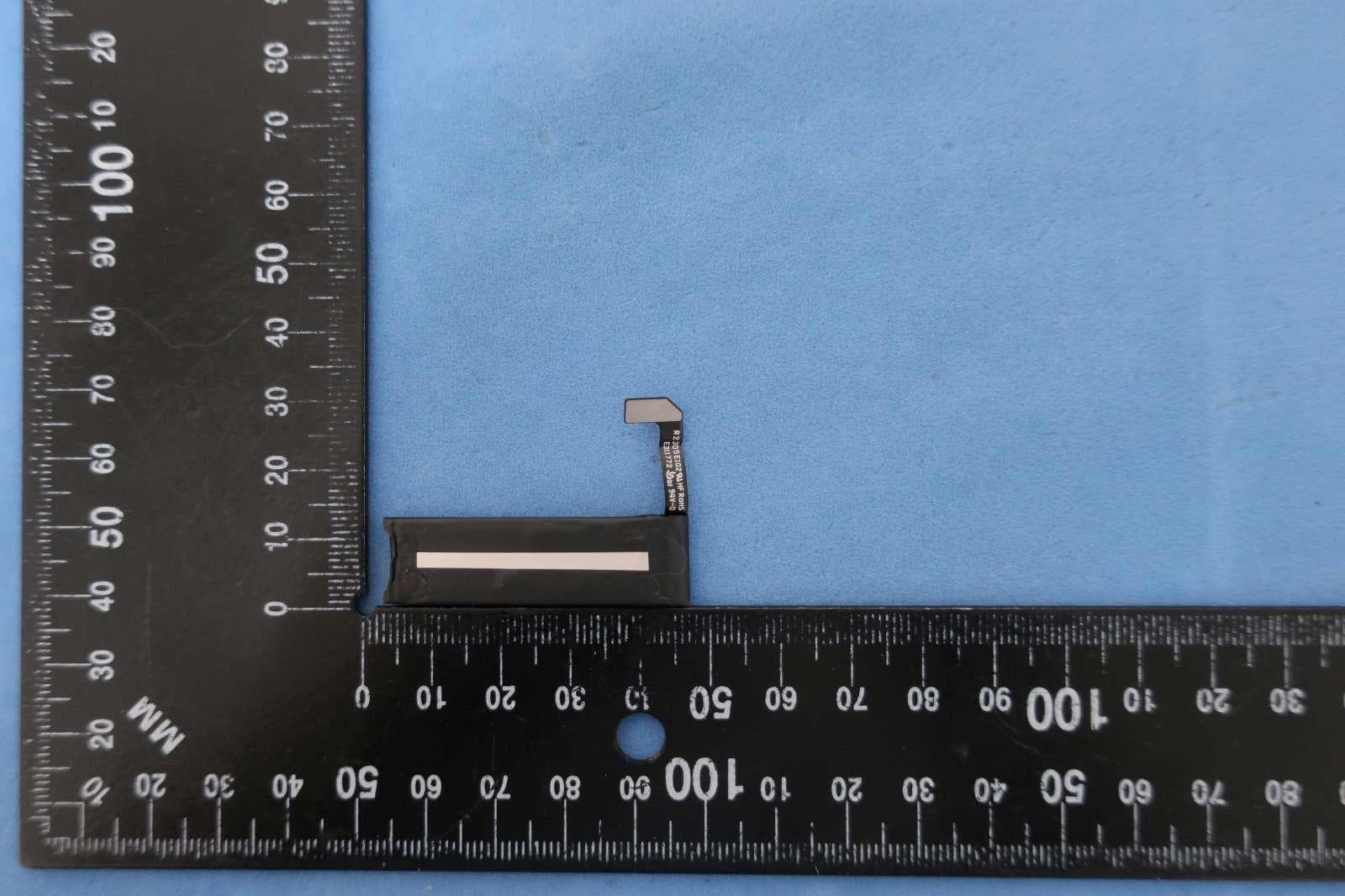
BXZSH4
Aug 02, 2023Myco 4 WiFi, Myco 4 Slim
Equipment Class
JBP - Part 15 Class B Computing Device Peripheral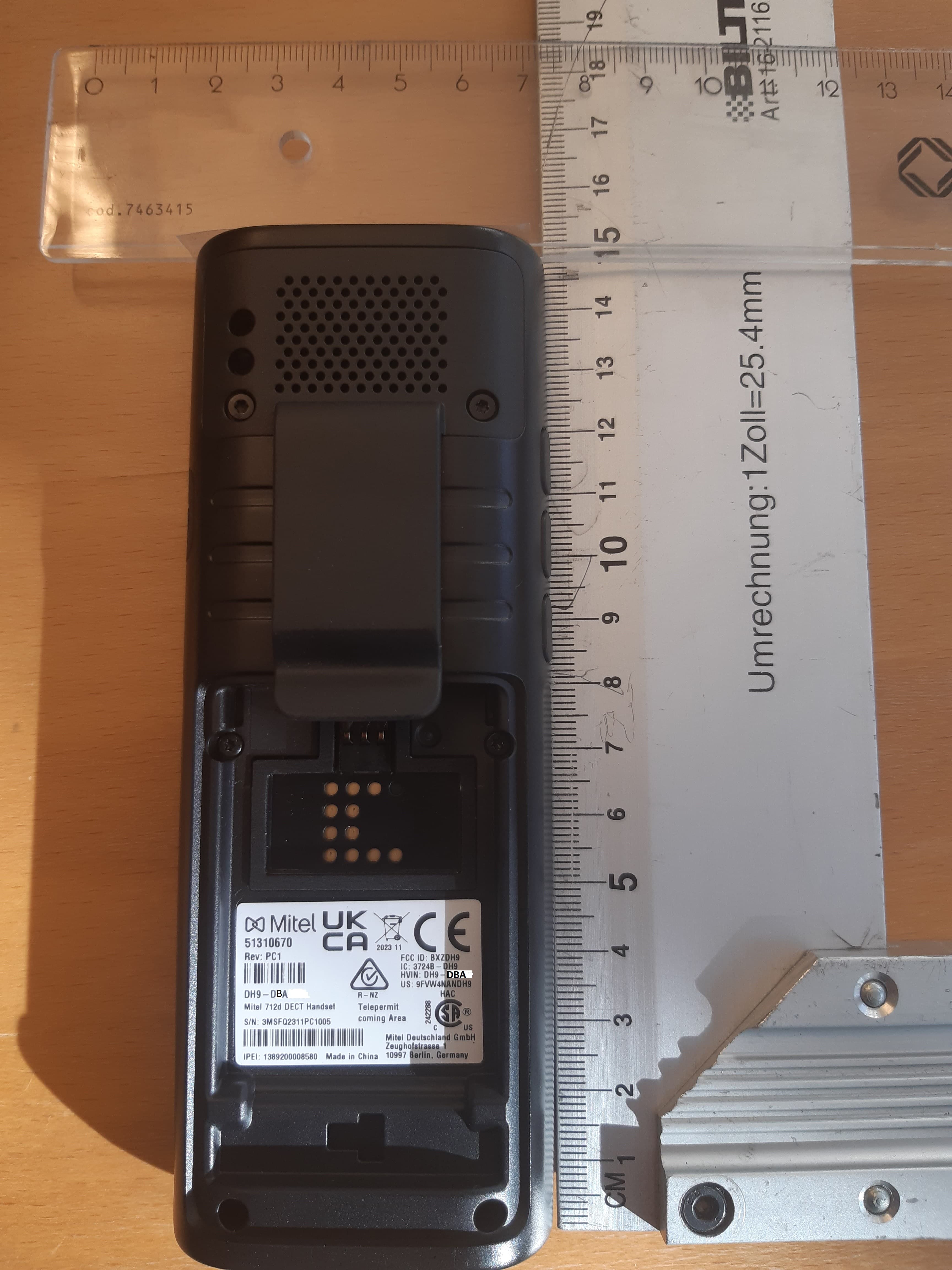
BXZDH9
Apr 16, 2023DECT Handset with Bluetooth
Equipment Class
PUE - Part 15 Unlicensed PCS portable Tx held to ear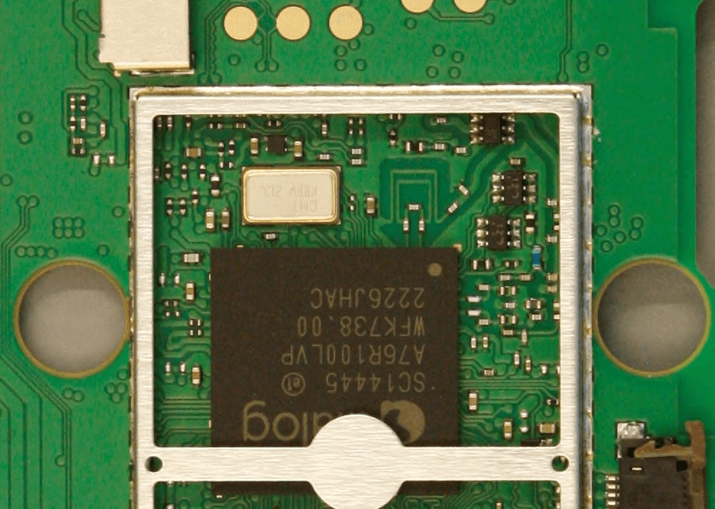
BXZDH10
Apr 16, 2023DECT Handset with Bluetooth
Equipment Class
DSS - Part 15 Spread Spectrum Transmitter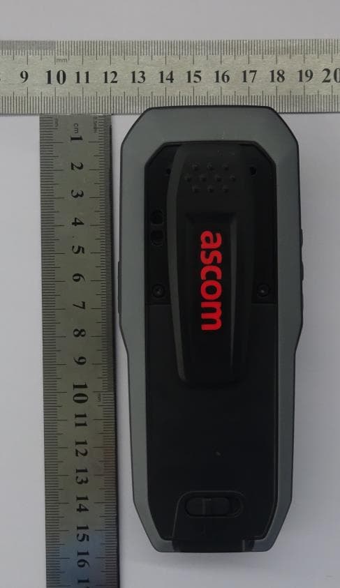
BXZDH8
Aug 09, 2021DECT Handset with Bluetooth and BLE
Equipment Class
JAB - Part 15 Class B Digital Device