BXZNUWPC3Wireless Customizable Pull Cord US
Ascom (Sweden) AB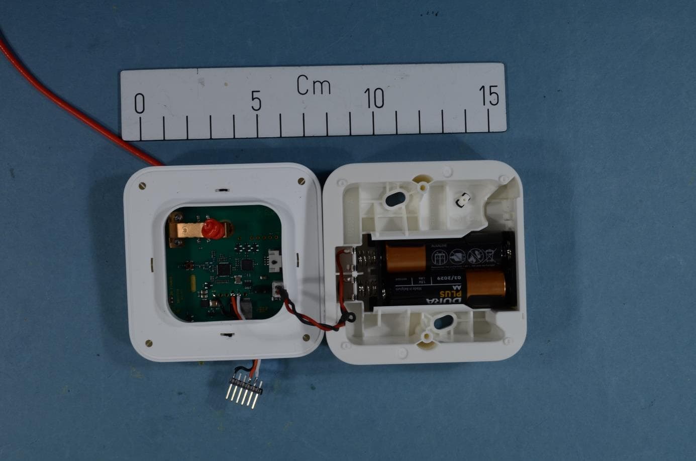
Click to zoom
Application Details
- Equipment Class
- DXT - Part 15 Low Power Transceiver, Rx Verified
- Date of Grant
- Jan 04, 2021
- Application Purpose
- Original Equipment
- Date of Application
- Jan 04, 2021
- Equipment Note
- Wireless Customizable Pull Cord US
- Frequency Range
- 916.21250000 - 920.21250000
- Company
- Ascom (Sweden) AB
- Country
- Sweden
Documents & Files
Document Text
Text extracted from the exhibit documents filed with the FCC. Open a document above to read the original.
Users Manual
TD 93025US 9 May 2019 / Ver. I System Description teleCARE IP Emergency Call System TD 93025US 9 May 2019 / Ver. I System Description teleCARE IP Copyright © 2019 Ascom (US), Inc. This document may not be copied in whole or in part or otherwise reproduced without prior written consent from Ascom, except where specifically permitted under US and international copyright law. Disclaimer The information in this document is subject to change. Use this product only in accordance with the instructions provided in the installation and user guide manuals. Use this product only in accordance with the purposes for which it is designed. For the latest version of all Ascom teleC- ARE documentation, contact your local supplier or visit the Ascom Partner Website at https:// www.ascom-ws.com. Trademarks and patents The teleCARE name and logo are trademarks of Ascom. Other trade names used in this document may be trademarks or registered trademarks of the manufacturers or vendors of the respective products. This publication may contain examples of screen captures and reports used in daily operations. Examples may include fictitious names of individuals and companies. Any similarity to names and addresses of actual businesses or persons is entirely coincidental. HIPAA disclaimer All examples of personal or protected health information in this document are fictitious. Any resemblance to a real person or facility is purely coincidental. The owners and users of this prod- uct are solely responsible for complying with all applicable protected health information privacy laws. The users, by their use of this product, agree to indemnify the manufacturer or seller of this product against all claims, litigation, and suits filed for protected health information violations. European Union directives The European directive “Waste Electrical and Electronic Equipment” (WEEE) aims to minimize the impact of electrical and electronic equipment waste on the environment and human health. To conform to this directive, electrical equipment marked with this symbol must not be disposed of in European public disposal systems. European users of electrical equipment must now return end-of-life equipment for disposal. Further information may be found on the following website: www.recyclethis.info . Battery Disposal This product may use sealed lead-acid batteries. Please refer to manufacturer instructions and all state, provincial, and local codes for information, instructions and requirements regarding proper disposal. Environmental Requirements Refer to the installation guide and product data sheet for complete product ratings and informa- tion. Avoid exposing the device to direct sunlight or other heat sources. Do not expose the device to open flame. Keep the device away from excessive heat and moisture. Protect your device from aggressive liquids and vapors. Keep the device away from strong electromagnetic fields. Terms used in this manual Specialized terms are used throughout this manual. The first time a term is used it is defined in the text. Regulatory Compliance (EU/EFTA) This equipment is intended to be used in the whole EU & EFTA. This equipment is in compliance with the essential requirements and other relevant provisions of EMC Directive 2014/30/EU and RoHS Directive 2011/65/EU. For NIRX/NITX/NILF/NICR/NIRD/ NUWGTW/NUREP/NUWIR/NUUTX/NUWBM3 products: Radio Equipment Directive 2014/53/EU and RoHS Directive 2011/65/EU. The Declaration of Conformity may be consulted at: http://www.ascom-ws.com/doc/ TD 93025US 9 May 2019 / Ver. I System Description teleCARE IP Regulatory Compliance (US/CAN) Copyright Safety Compliance: The equipment described herein complies with: ANSI/UL 2560 Emergency Call Systems for Assisted Living and Independent Living Facilities CAN/CSA C22.2 No. 205 Signal Equipment Note: This equipment has been tested and found to comply with the limits for a Class B digital device, pursuant to Part 15 of the FCC Rules. These limits are designed to provide reasonable protection against harmful interference in a residential installation. This equipment generates, uses, and can radiate radio frequency energy and, if not installed and used in accordance with the instructions, may cause harmful interference to radio communications. However, there is no guarantee that interference will not occur in a particular installation. If this equipment does cause harmful interference to radio or television reception, which can be deter- mined by turning the equipment off and on, the user is encouraged to try to correct the interfer- ence by one or more of the following measures: Reorient or relocate the receiving antenna. Increase the separation between the equipment and receiver. Connect the equipment into an outlet on a circuit different from that to which the receiver is connected. Consult the dealer or an experienced radio or television technician for help. Information to user: This device complies with Part 15 of the FCC Rules. Operation is subject to the following two conditions: i) this device may not cause harmful interference, and ii) this device must accept any interference received, including interference that may cause undesired operation. This device complies with Industry Canada license-exempt RSS standard(s). Operation is subject to the following two conditions: (1) this device may not cause interference, and (2) this device must accept any interference, including interference that may cause undesired operation of the device. Le présent appareil est conforme aux CNR d'Industrie Canada applicables aux appareils radio exempts de licence. L'exploitation est autorisée aux deux conditions suivantes: (1) l'appareil ne doit pas produire de brouillage, et (2) l'utilisateur de l'appareil doit accepter tout brouillage radioélectrique subi, même si le brouil- lage est susceptible d'en compromettre le fonctionnement. CAN ICES-3 (B)/NMB-3(B) Modifications: Changes or modifications to the equipment not expressly approved by the p…
Text truncated - open the document above for the full version.
Users Manual
TD 93025US 9 May 2019 / Ver. I66 System Description teleCARE IP The fixed transceiver includes an 8-pole connector for a hard wire of a conventional teleCARE M switch modules, or a dome lamp, or an external technical alarm contact (N/O). The fixed transceiver LEDs stay active for a period of 30 seconds after a call has been made, except for staff presence indication which stays active until it is cancelled by the staff. Note: Leaving a fixed transceiver in staff presence state will have a negative impact on the battery life time and therefore it is advised to power the NIFX externally when using an NIFX template that includes staff presence functionality. When externally powered, the red, yellow and green LEDs will permanently emit a low intensity light for locating and identification in the dark. The socket module version of the fixed transceiver includes a teleCARE Safe Release socket for connecting the NIPH or NIPH2-B1A handset with handset disconnect alarm functionality. Speech/Entertainment handsets are not supported. 9.6.6 NITX Mobile transceiver The NITX mobile transceiver is a wireless call unit for residents. It is robust and water resistant (IP 65). The NITX mobile receiver is available in two versions: •NITX-AAB for residents containing an 916-921 MHz RF transceiver, a call button and a reassurance LED •NTX-BAB for residents containing an 916-921 MHz RF transceiver, a call button and a reassurance LED. It also contains a 125 kHz LF receiver used for call cancellation by a staff transceiver and for location determination using LF beacons. Figure 61. teleCARE IP mobile transceiver (wrist and pendant) The mobile transceiver is delivered with a plastic wrist strap so that it can be worn like a wrist watch. Alternatively, it can be placed in a pendant holder and attached to a lanyard so that it can be worn around the neck. The pendant holder and lanyard must be ordered separately. The mobile transceiver is powered by a 3 volt lithium replaceable battery. The battery voltage is continually monitored and if low voltage is detected a “low battery” alarm is transmitted as part of the heartbeat transmission of the unit. Under normal circumstances the battery life is 1 to 1 ½ year. TD 93025US 9 May 2019 / Ver. I67 System Description teleCARE IP A normal call is activated by a short press on the button, an assistance call is activated by pressing the button for longer than 3 seconds. When a call has been made, a delay of one minute will prohibit the NITX from sending updates (of the same call type) to prevent draining the internal buffer capacitor too fast, this will prevent triggering false battery low alarms. A call can be cancelled locally by 1 long press followed by 3 short presses within 3 seconds. Remote cancelling can be done by a 3 button doorside module or a portable messaging device, such as an Ascom handset. The mobile transceiver sends a “Heartbeat” signal at regular intervals (default 4 minutes). If the system fails to receive the heartbeat signal within a predetermined period then it is assumed that the transceiver has failed or is missing and an alarm will automatically be generated. An infrared proximity detector which monitors the correct attachment of the mobile transceiver on the wrist is located at the back of the mobile transceiver. If the mobile transceiver is removed from the wrist the infrared proximity detector will detect and automatically activate a “mobile transceiver detached” alarm. A motion detector detects when the mobile transceiver is in motion. If a mobile transceiver stays motionless for more than two hours it will automatically activate a no-motion alarm. 9.6.7 NITX Staff Transceiver The NITX-BBB staff transceiver is for staff members. It is robust and water resistant (IP 67). Figure 62. teleCARE IP staff transceiver (wrist and pendant) The NITX-BBB staff transceiver contains an 916-921 MHZ RF transceiver, a call button and a reassurance LED. It also contains a125 kHz LF transceiver used for cancelling calls from other NITX (BAB) and NIFX (1AB and 1BB) transceivers and for location determination using LF beacons. The NITX-BBB staff transceiver cancels calls initiated from other NITX (BAB) and NIFX (1AB and 1BB) transceivers through an LF transmission and provides the identification of the staff member cancelling the call. A staff member can also initiate an assistance call from the staff transceiver when in need of assistance. It is used in the teleCARE IP system. A call cancellation (LF transmission) is activated by a short press on the green button when in close proximity (up to 30cm) of a wireless call device that includes an LF receiver. An assistance call (RF transmission) is activated by a long press (more than 3 seconds) on the green button. TD 93025US 9 May 2019 / Ver. I68 System Description teleCARE IP Mobile transceiver Accessories Interchangeable rings, buttons and strap loops make it possible to customize the mobile transceiver body. The four types of rings, six buttons and four strap loops are available as accessories in a variety of colours which can be ordered separately. A special tool is supplied for removing the ring. Figure 63. Mobile transceiver accessories Replacement Rings Dark grayMetallic Light grayWhite Ring mounting tool Colored Buttons Dark grayRed MetallicGreen WhiteOrange Continued on the next page TD 93025US 9 May 2019 / Ver. I69 System Description teleCARE IP Colored Loops OrangeAqua OrchidLime Wrist Straps and Pendant Kit Pendant holderPendant lanyard Wrist straps TD 93025US 9 May 2019 / Ver. I70 System Description teleCARE IP 9.6.8 NUUTX Universal Transceiver The universal transceiver module (NUUTX-HU) is a wall mounted teleCARE IP wireless peripheral containing a 916 - 921 MHz RF transceiver which can be mounted on walls, door or window posts. The NUUTX has two independent inputs that can be used to interface external alerts coming from a wide variety of detectors and alarm contacts. The inputs support: • Normally open…
Text truncated - open the document above for the full version.
Users Manual
PRELIMINARY INSTALLATIONGUIDE WirelessPull CordModule(NUWPC3– Hx) PRELIMINARY Introduction INSTALLATIONGUIDE WirelessPullCordModule(NUWPC3–Hx) 1Introduction 1.1Symbols Readthemanualformoreinformation Caution:Useextremecautionandfollowinstructionscarefully. 1.2Description TheWirelessPullCordModuleNUWPC3communicateswiththecontroller(NIRC3/NIRC4)ora repeater (NUREP).TheNUWPC3pullcordis batterypoweredwithtwoAAAlkalinebatteries.Thebatteriescanbe easilyreplacedusingthebatterypackviathebatterydoorinthespacer. 1.3Installation TheNUWPC3hasanIP44ingressprotection.TheareasinwhichNUWPC3saretobeinstalledmustbe clean,dry(duringinstallation),andweatherproof.Thewallsonwhichdevicesaretobeinstalledshouldbe finished(painted,wallpapered,tiled,etc.)beforethedevicesareinstalled.It is importanttomountthe NUWPC3awayfromanydirectwateringression. 1.4ImportantSafetyInformation TheWirelessPullCordModule(NUWPC3)InstallationInstructionscontainimportantinstructionsforuse duringinstallationandmaintenanceoftheNUWPC3.Toensurea safeworkingenvironmentduringthe installationandoperationoftheNUWPC3,thefollowingsafetysymbolsappearthroughoutthisdocument toindicatedangerousconditionsandimportantsafetyinstructions. Caution:Useextremecautionandfollowinstructionscarefully. 1 TD93427EN/ 30October2020/ Ver.PA4 PRELIMINARY INSTALLATIONGUIDE WirelessPullCordModule(NUWPC3–Hx) Introduction 1.5RegulatoryComplianceUS/CAN ForfurtherinformationabouttheteleCAREsystemproductssee“SystemDescription”TD93025,where alsoinformationregardingRegulatorycompliancecanbefound. TD93427EN/ 30October2020/ Ver.PA4 2 PRELIMINARY Mounting INSTALLATIONGUIDE WirelessPullCordModule(NUWPC3–Hx) 2Mounting ThebaseoftheNUWPC3mountsdirectlyontoflatwallorceilingsurfaces. Caution:Topreventa firehazardbecauseofdustbuildupinsidetheNUWPC3,regular inspectionand/orcleaningoftheNUWPC3is required. Caution:Takepropermeasurestoavoidspreadingdustandotherparticleswhenapplying maintenancetoanNUWPC3thatis mountedinsidea clinicalarea. 2.1Mountingthe Spaceron the wall or ceiling WhenmountingtheNUWPC3ona wallorceilingwithouta backbox,mountthebasedirectlytoa flatwall surfaceusingtwoscrewssuitableforthewalltype. Whenchoosinga walllocationforanNUWPC3,considertheingressionprotection. TheNUWPC3shallonlybemountedwiththeincludedbase. Donotdistortortwistthebasewhenmountingit toa wall.If thebaseis distorted,theNUWPC3– Hxmodulewillnotfitproperlyandmaynotbeprotectedagainstwateringression. Figure1. NUWPC3BaseOrientationand mounting Legend 1.Screwholesforwallorceilingmounting 2.Screwholesformodule 3.Batterydoor 4.Batteryconnector 3TD93427EN/ 30October2020/ Ver.PA4 PRELIMINARY INSTALLATIONGUIDE WirelessPullCordModule(NUWPC3–Hx)Mounting To mountthe NUWPC3baseon a wall 1.Placethebaseagainsta flatwallandorientit sothatthebatterydooris pointingdownandthatthe baseis level.Orplacethebaseagainsttheceiling.Usea levelingdevicetocheck,if necessary. 2.Makesurethatthereis roomtoremovethebatterypackfromthebasebeforemountingthebase. (SeeFigure1.NUWPC3BaseOrientationand mounting,page3,item2.) 3.Usingthebaseasa template,markthetwoslottedholes(SeeFigure1.NUWPC3BaseOrientationand mounting,page3,item1.)forthescrewslocatedinthebase. 4.Removethebasespaceranddrillholesforthescrewsthatwillbeused,suchaswood,concrete,or drywallscrews,orscrewswithanchors. 5.Placethebaseovertheholes,insertthescrews,andthentighten. Caution:TheNUWPC3mustbemountedina waythatthemoduleis firmlyattachedtothe background. Thebasehasa gaskettopreventwateringressionfromtherear.Incaseofuneven background,useanapplicablecaulktocaulkaroundthebaseandthebackground.Make surethatthebatterydooris notblockedbythecaulk. 2.2Mountingthe moduleon the spacer 1.Placethegasketonthespacerandorientthegasketsoit fitsneatly. 2.Pullthebatterywiresandconnectorthroughthegasket. TD93427EN/ 30October2020/ Ver.PA4 4 PRELIMINARY Mounting INSTALLATIONGUIDE WirelessPullCordModule(NUWPC3–Hx) 3.Insertthebatteryconnector(SeeFigure1.NUWPC3BaseOrientationand mounting,page3,item4) intothesocketontherearsideofthemodule. 4.Placethemoduleonthegasketandmakesureit fitsneatly. 5.Usethe2 providedscrewsanda Phillipsscrewdrivertoscrewthemoduleontotheholesinthespacer (SeeFigure1.NUWPC3BaseOrientationand mounting,page3,item3).Tightenthescrews,butdonot overtightenthem. 6.Connectthebottomhalfofthecordtothepartcomingfromthemodule.Thetwohalvesshouldfirmly clicktogether. 5TD93427EN/ 30October2020/ Ver.PA4
Users Manual
PRELIMINARY INSTALLATIONGUIDE WirelessPullCordModule(NUWPC3–Hx)Mounting 7.Adjustthelengthofthecord: • Liftthebottombarrelofthecord(item1). • Cutthecordabout2.5cm(1 in)belowthedesiredlength(item2). • Tiea doubleknotattheendofthecordbyloopingtheendofthecordtwicethroughtheloop(item3). • Pulltheknottightly(item4). 2.3Placingof batteries 1.• Openthebatterydoorofthebase(item1). • Removethebatterypackfromthebase(item2).Thebatterypackis keptinplacebya smalledge.Lift thepackoverthisedge. 2.Place2 x 1.5VAAdisposableAlkalinebatteries(notincluded)inthebatterypack,payattentiontothe polarityofthebatteries. TD93427EN/ 30October2020/ Ver.PA46 PRELIMINARY Mounting INSTALLATIONGUIDE WirelessPullCordModule(NUWPC3–Hx) TheNUWPC3is protectedagainstreversepolarityofthebatteries. Whenbatteriesotherthantherecommendedonesareused,theNUWPC3is protectedbya thermistor(PTC).Thecorrectworkingcannotbeguaranteed. 3.• Placethebatterypackbackintothebase(item1).Liftthebatterypackintothemoduleandplaceit overthesmalledgetokeepit inplace. • Closethebatterydoor.(item2) Thebatterypackfitsonlyonewayintothebase. Whenthebatterypackis inserted,the3 buttonLEDswilllightupinsequencestartingwiththe topLED.Thisconfirmsthatthemoduleis workingproperly. 4.Checkthecorrectworkingofthemodule:Generatea callbypullingthecord. Onlyina correctlyconfiguredsystemwillthecallgenerateanalarmondisplaydevicessuch ascorridorlamps. 5.For newinstallation:Placethe2 providedscrewcapsoverthescrewholes.Orientthemcorrectly.The capshavea smallprotrusionthatfitsneatlyintothesmallindentationofthemodule,seedetailbelow 2.4Removingthe module RemovaloftheNUWPC3fromwallorceiling. 1.Removethebatterypackfromthemodule: • Openthebatterydoorofthebase(item1). 7 TD93427EN/ 30October2020/ Ver.PA4 PRELIMINARY INSTALLATIONGUIDE WirelessPullCordModule(NUWPC3–Hx)Mounting • Removethebatterypackfromthebase(item2).Thebatterypackis keptinplacebya smalledge.Lift thepackoverthisedge. 2.Removethe2 screwcaps: • Inserta smallflattippedscrewdrivernexttothecap(item1). • Twistthescrewdriverandpopoutthecap(item2). 3.Removethe2 screwswitha #2Phillipsscrewdriver. 4.PulltheModulegentlyawayfromthebase.Themoduleis stillconnectedtothebaseviathebattery packwires. 5.Disconnectthebatteryconnectorfromtherearofthemodule TD93427EN/ 30October2020/ Ver.PA48 PRELIMINARY Mounting INSTALLATIONGUIDE WirelessPullCordModule(NUWPC3–Hx) 2.5Replacingthe buttoninsert 1.Removecurrentbuttoninsertbygentlypullingthesmalltabatthelowerendoftheinsertwitha small pairofpliers. 2.Inserta newbuttoninsertfromthelowerendofthemodule.Makesuretheinsertfitscompletelyinthe membrane. Thebuttoninsertshouldbewaterresistant. 3.CheckthatallofthebuttonLEDsarevisible: Removethebatterypackandinsertagain:the3 buttonLEDswilllightupinsequencestartingwiththe topLED.Thisconfirmsthatthemoduleis workingproperly. 9TD93427EN/ 30October2020/ Ver.PA4 PRELIMINARY 10TD93427EN/ 30October2020/ Ver.PA4 PRELIMINARY Ascom(Sweden)AB Grimbodalen2 SE–41749Göteborg Sweden Phone+4631559300 www.ascom.com TD 93427EN / 30 October 2020 / Ver. PA4 lastpage
Cover Letter(s)
Ascom (Sweden) AB Page 1(2) PO Box 8783, SE402 76 Gothenburg, Sweden T +46 31 55 93 00, F +46 31 55 20 31 www.ascom.com Org.nr./F-skatt 556336-6292, VAT No. SE556336629201, REG. Office: GÖTEBORG 28 October, 2020 Equipment Autorisation Division Federal Communications Commission 7435 Oakland Mills Road Columbia, MD 21046 Ascom (Sweden) AB FCC Registration Number (FRN): 0013904214 FCC IO: BXZNUWPC3 Product Name: Wireless Customizable Pull Cord US Pursuant to Sections 0.457 and 0.459 of the commissions rules, we hereby request that the following documents be held confidential: • Operational Description • Block Diagram • Schematics • Parts Lists • Tune Up Information • HW Design Description These documents contain detailed system and equipment description and related information about the product which Ascom (Sweden) AB considers being proprietary, confidential and a custom design and otherwise would not release to the general public. Since the design is a basis from which future technological products will evolve, Ascom (Sweden) AB considers that this information would be of benefit to its competitors and that the disclosure of the information in these documents would give competitors an unfair advantage in the market. In addition to the above mentioned documents, pursuant to Public Notice DA 04-1705 of the Commission’s policy, in order to comply with the marketing regulations in 47 CFR §2.803 and the importation rules in 47 CFR §2.1204, while ensuring that business sensitive information remains confidential until the actual marketing of newly authorized devices, Ascom requests that the Commission withholds the following documents from public viewing for one hundred eighty days after the date the grant of equipment authorization is issued: • External Photographs • Internal Photographs • Test Setup Photographs These documents reveal technical and design information that has not been publicly disclosed in marketing materials and is protected by Ascom (Sweden) AB as confidential and proprietary trade secrets. This information has been disclosed to those required to maintain its confidentiality confidentiality, and is not customarily disclosed publicly prior to the commercial release of the device. As a result, disclosure of this information by the Commission prior to commercial release would harm Ascom (Sweden) AB by giving competitors an unfair market advantage. Ascom (Sweden) AB believes Ascom (Sweden) AB Page 2(2) PO Box 8783, SE402 76 Gothenburg, Sweden T +46 31 55 93 00, F +46 31 55 20 31 www.ascom.com Org.nr./F-skatt 556336-6292, VAT No. SE556336629201, REG. Office: GÖTEBORG the period of confidentiality requested is necessary to protect the information until the commercial release of a device. If you have any questions, please feel free to contact me at the address shown below. Dated this 28 Day of October 20 20 By: Bodil Tufvesson Signature Printed Title: Regulatory Affairs Engineer Telephone: +46 31559563 Applicant: Ascom (Sweden) AB
External Photos
EXTERNAL PHOTOS Project no.: 406902 FCC ID: : BXZNUWPC3 Page 1 (2) EXTERNAL PHOTOS – NUWPC3-HU Top side Rear side EXTERNAL PHOTOS Project no.: 406902 FCC ID: : BXZNUWPC3 Page 2 (2) Side view Back view
ID Label/Location Info
Made in Thailand Fabriqué en Thaïlande Insert date code at time of label printing. Made in Thailand Fabriqué en Thaïlande Ascom(Sweden)AB Grimbodalen 2 417 49 Göteborg, Sweden Australian RCM-symbol height not less than 3 mm All element to of the enhanced UL Certification Mark must be printed exactly as shown wrt. color, orientation, content etc. The enhanced UL Certification Mark cannot be reproduced any smaller than 8mm when it is selfstanding. Note: UL Mark with back background and white background are allowed. Label specification The symbol indicating separate collection for EEE consists of the crossed-out wheeled bin. The symbol must be printed visibly, legibly and indelibly. This document contains confidential and proprietary information of Ascom and may not be copied, used or disclosed without the written permission of Ascom and must be returned upon request. When used, the CE mark must have a height for a good visibility. Wireless Customizable Pull Cord US Model: NUWPC3-HU /xx Model: NUWPC3-HU/xx yyyy-mm-dd yyyy-mm-dd ID:YYYYYY G1234567 yyyy-mm-dd IC: 3724B-NUWPC3 FCC ID: BXZNUWPC3 IC: 3724B-NUWPC3 R-NZ FCC ID: BXZNUWPC3 R-NZ Serial number, 8 characters. Device ID with Barcode in 128 format S/N: Barcode is code 128 format or a Data matrix ≥ 3mm S/N ≥ 8mm China RoHS mark: Height > 5mm ID: YYYYYY ID: YYYYYY S/N: G1234567 Complies with IMDA Standards DA107674 IMDA marking for radio/telecom approved devices in Singapore Complies with IMDA Standards DA107674 Unite radio d’appel toilettes personnalisable US Degree of protection provided by enclosure (IP Code) IP44 IP44 HVIN: NUWPC3-904643 HVIN: NUWPC3-904643
ID Label/Location Info
Note! This drawing shall not be duplicated or used for any purpose other tan that for which provided. The information disclosed here in originated by and is the property of Ascom, and except for rights explicitly granted by written consent, such information shall not be disclosed or disseminated whole or in part. Ascom reserves all rights in the event of the grant of patent, copyright, design, use, sale, manufacturing and reproduction rights there to. 1 SIZE A3 A B C D E F 12345678 F E D C B A 8765432 0.05 0.02 10 0.02 400.02 5 RevChange Description:Change Date: Changed By:Approved By: A TBD Pos.:Cad-Model Nr.:/Type:Cad-Model Name (Common Name):Qty.:Notes: Authoring Application: Creo Parametric Title:General tolerances acc. to ISOScale: LABEL BLANK 10X40MM Dimensions acc. to ISO-2768 2:1 GD and T acc. to ISO 1101 Projection: Surface roughness std. acc. to ISO 1302 Resp. Engineer:Originally Drawn By:Originally Approved:Drawing no.Revision: Nermin Hromic M BodiNermin Hromic M69302A Gothenburg Sweden Creation Date: Format: A3Sheet: 1/1 Model version: B.1 Drawing version: A.1 Model modified? NO Drawing modified? *** CAD Model Name: M68630 Safety & Compliance Ex (!C):NO El.safety (!S):NO MDD:NO FAR SIDE (ADHESIVE): Perforate paper backing here to allow removal in two sections Each section should have easy pull tab for removal 2016-12-02 FUNCTIONAL DIMENSIONING The part described on this drawing is represented in graphic detail to show all of its features for the purpose of engineering documentation. Only those dimensions which affect the fit and function of the overall product assembly have been included for various purposes of inspection. Listed below All dimensions and drw note requirements shown shall be inspected and reported for initial part qualification. Dimensions noted with an " "are critical dimensions and must be inspected according to a control plan in a reoccurring process. Dimensions noted with an" "are process control (cp,cpk) dimensions and must be inspected and stored in a continuous process. All remaining features, not specified by dimension and tolerance, are cosmetic and mostly for the manufacturability of the part, but must still be approved by Ascom Engineering Department prior to initial qualification of the tool and part. The dimensional values for features not dimensioned are to be obtained from the Digital Shape Model (DSM) listed in the title block. The allowable tolerance on these features shall be as stated in the general tolerance chart ISO 2768 or GD &T "Profile of surface" symbol in the text note block. X X Notes: 1. Material: Self Adhesive Film, PET50K2411 PA-T1 8K 2. Digital shape model no.: M69302_A.igs and/or .stp is basis where dimensions are omitted 3. Label durability according to PGDQ2 or PGJI2 4. Label layout according to Ascom Agile /PLM-system 5. Color according to Ascom Agile /PLM-system 6. Tolerances according to ISO 2768-c 7. To be supplied with protective liner for adhesive 8. Purchasing cycle max 6 months to avoid adhesive deteriation before use 9. RoHS and REACH compliant
Internal Photos
INTERNAL PHOTOS Project no.: 406902 FCC ID: : BXZNUWPC3 Page 1 (1) INTERNAL PHOTOS – NUWPC3-HU Top view – main board (with test leads white,red and black) Rear view – main board (with test leads white,red and black)
RF Exposure Info
FCC ID: BXZNUWPC3 SAR Exclusion Justification Test exclusion thresholds for 100 MHz to 6 GHz at test separation distances ≤ 50 mm Guidance document reference: 447498 D01 General RF Exposure Guidance v05r02, page 11, paragraph 4.3.1(1). The 1-g and 10-g SAR test exclusion thresholds for 100 MHz to 6 GHz at test separation distances ≤ 50 mm are determined by: [(max. power of channel, including tune-up tolerance, mW)/(min. test separation distance, mm)] * [√f(GHz)] ≤ 3.0 for 1-g SAR and ≤ 7.5 for 10-g extremity SAR, where • f(GHz) is the RF channel transmit frequency in GHz • Power and distance are rounded to the nearest mW and mm before calculation • The result is rounded to one decimal place for comparison • 3.0 and 7.5 are referred to as the numeric thresholds in the step 2 below The test exclusions are applicable only when the minimum test separation distance is ≤ 50 mm and for transmission frequencies between 100 MHz and 6 GHz. When the minimum test separation distance is < 5 mm, a distance of 5 mm according to 5) in section 4.1 is applied to determine SAR test exclusion. SAR test exclusion analysis: Assumptions: Since the exact separation distance may vary from sensor to sensor, the minimum separation distance of 5 mm is assumed per the guidance document. Max. power of channel: 0.67 mW Min. separation distance: 5 mm Max. frequency: 0.91821 GHz [(Pwr/Dist)* √ Freq.] = 0.1 Max. power is source-based time-averaged maximum conducted output power, adjusted for tune-up tolerance. The result of the above SAR threshold calculation demonstrates that the result is less than the 1-g numeric threshold of 3 and the 10-g numeric threshold of 7.5. Conclusion: The above analysis shows that the evaluated device qualifies for exemption from SAR testing. Signed: , Senior Enginner 10/30/2020
Test Setup Photos
TEST SET-UP PHOTOS Project no.: 406902 FCC ID: BXZNUWPC3 Page 1 (1) PHOTOS OF TEST SET-UP Test setup , YZ Plane Test setup , XZ Plane Test setup, XY Plane Radiated emissions , below 1GHz Radiated emissions , above 1GHz
Contact Information
Applicant
Peter Soderberg
Test Firm
Nemko Scandinavia ASTor Erik Pedersen
[email protected]+4798228176
Technical Specifications
| # | Rule Parts | Frequency Range | Power Output |
|---|---|---|---|
| 1 | 15C | 916.2125 MHz - 920.2125 MHz | - |
Other Applications from Ascom (Sweden) AB

BXZCHAT2
Sep 27, 2023Narrow band alarm transceiver
Equipment Class
TNB - Licensed Non-Broadcast Station Transmitter
BXZSH4
Aug 02, 2023Myco 4 WiFi, Myco 4 Slim
Equipment Class
JBP - Part 15 Class B Computing Device Peripheral
BXZDH9
Apr 16, 2023DECT Handset with Bluetooth
Equipment Class
PUE - Part 15 Unlicensed PCS portable Tx held to ear
BXZDH10
Apr 16, 2023DECT Handset with Bluetooth
Equipment Class
DSS - Part 15 Spread Spectrum Transmitter
BXZDH8
Aug 09, 2021DECT Handset with Bluetooth and BLE
Equipment Class
JAB - Part 15 Class B Digital Device