BY32160-24B1B/O Toys
Scientific Toys Ltd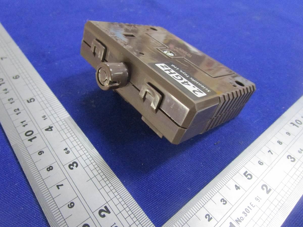
Click to zoom
Application Details
- Equipment Class
- DXX - Part 15 Low Power Communication Device Transmitter
- Date of Grant
- Mar 26, 2020
- Application Purpose
- Original Equipment
- Date of Application
- Mar 26, 2020
- Equipment Note
- B/O Toys
- Frequency Range
- 2422.00000000 - 2462.00000000
- Company
- Scientific Toys Ltd
- Country
- Hong Kong
Documents & Files
Document Text
Text extracted from the exhibit documents filed with the FCC. Open a document above to read the original.
Users Manual
UM-4 OR LR03 UM-4 OR LR03 UM-4 OR LR03 UM-4 OR LR03 UM-4 OR LR03 UM-4 OR LR03 Back Panel of transmitter 2 x AAA/LR03 batteries Unscrew to open OPERATING INSTRUCTIONS: INSTRUCTION SHEET & PACKAGING MUST BE RETAINED SINCE IT CONTAINS IMPORTANT INFORMATION. Remember to take out all batteries from spider and transmitter after playing. 1. Do not mix old and new batteries. 2. Do not mix alkaline, standard (Carbon-Zinc), or rechargeable batteries. BATTERY INSTALLATION (FOR MAXIMUM PERFORMANCE, ONLY USE ALKALINE BATTERIES) SPIDER 1. Make sure the ON/OFF switch of the spider is at the OFF position. (See Diagram 1) 2. Unscrew to open the battery cover. (See Diagram 1) 3. Insert batteries by matching (+) and (-) sign as indicated in the battery pack. (See Diagram 2) 4. Replace and screw the battery cover. TRANSMITTER 1. Remove battery cover and install 2 x AAA batteries by matching (+) and (-) sign as indicated in the battery compartment. (See Diagram 3). 2. Replace the battery cover. HOW TO PLAY START TO PLAY 1. Push the ON/OFF switch to the "ON" position of the spider. (See Diagram 4) FORWARD RUNNING 2. Push the Driving Control Stick forward for forward running. (See Diagram 5) REVERSE RUNNING 3. Pull the Driving Control Stick backward, the spider will turn in reverse. (See Diagram 6) STOP OPERATION 4. Release the Driving Control Stick to stop the spider. PERFORMANCE TIPS: - Don't drive in grass, sand or on carpet. - Don't go through water. - Use fresh alkaline batteries. - Be sure to rest your spider for at least 30 minutes after every 15 minutes of operation. - Make sure ON/OFF switch on your spider is OFF when not in use. - Don't bend antenna. - Electrical, CB interference, mobile phones, air conditioning, elevators and steel girders in building will affect the operation of your spider. - Don't leave the spider or transmitter near sources of heat or under direct sunlight for long periods of time. - Remove the batteries from the spider and transmitter when not in use. BATTERY CAUTIONS 1. For maximum performance, use alkaline batteries. 2. Do not mix old and new batteries. 3. Do not mix alkaline, standard (carbon-zinc), or rechargeable batteries. 4. Do not recharge non-rechargeable battery. 5. Ensure batteries are inserted with the correct polarity. 6. Remove batteries when toy is not in use. 7. Remove exhausted batteries from toy and dispose of in accordance with the makers recommendation. 8. Rechargeable batteries should only be charged under adult supervision. 9. Remove rechargeable batteries from toy before charging. 10. The supply terminals are not to be short-circuited. 11. The antenna wires are not to be inserted into socket outlet. NOT SUITABLE FOR CHILDREN UNDER 3 YEARS OF AGE, DUE TO SMALL PARTS. FCC NOTE: THE ANTENNA PROVIDED IS A UNIQUE ANTENNA. BY INSTALLATION OF UNAUTHORIZED ANTENNA TO THIS EQUIPMENT. SUCH UNAUTHORIZED INSTALLATION COULD VOID THE USER’S AUTHORITY TO OPERATE THE EQUIPMENT. THE MANUFACTURER IS NOT RESPONSIBLE FOR ANY RADIO OR TV INTERFERENCE CAUSED BY UNAUTHORIZED MODIFICATIONS TO THIS EQUIPMENT. SUCH MODIFICATIONS COULD VOID THE USER’S AUTHORITY TO OPERATE THE EQUIPMENT. Warning: Changes or modifications to this unit not expressly approved by the party responsible for compliance could void the user’s authority to operate the equipment. NOTE: This equipment has been tested and found to comply with the limits for a Class B digital device, pursuant to Part 15 of the FCC Rules. These limits are designed to provide reasonable protection against harmful interference in a residential installation. This equipment generates, uses and can radiate radio frequency energy and, if not installed and used in accordance with the instructions, may cause harmful interference to radio communications. However, there is no guarantee that interference will not occur in a particular installation. If this equipment does cause harmful interference to radio or television reception, which can be determined by turning the equipment off and on, the user is encouraged to try to correct the interference by one or more of the following measures: - Reorient or relocate the receiving antenna. - Increase the separation between the equipment and receiver. - Connect the equipment into an outlet on a circuit different from that to which the receiver is connected. - Consult the dealer or an experienced radio/TV technician for help. ATTENTION PARENTS: IT IS RECOMMENDED THAT THIS TOY AND ALL ACCESSORIES BE PERIODICALLY EXAMINED FOR POTENTIAL HAZARDS AND THAT ANY POTENTIALLY HAZARDOUS PARTS BE REPAIRED OR REPLACED. WARNING: CHOKING HAZARD- Small parts, Not for chidren under 3 years © 2019 SCIENTIFIC TOYS LTD. 1108, TOWER B, 14 SCIENCE MUSEUM ROAD, TSIMSHATSUI, HONG KONG. PRINTED IN CHINA O.I. NO.6521 Diagram 3
External Photos
Page 1 of 2 External Photos Page 2 of 2
Internal Photos
Page 1 of 4 Internal Photos Page 2 of 4 Page 3 of 4 Page 4 of 4
RF Exposure Info
1 INTERTEK TESTING SERVICES RF Exposure The equipment under test (EUT) is a B/O Toys operating at 2.4G Band. The EUT can be powered by DC 3.0V (2 x 1.5V AAA batteries). For more detail information pls. refer to the user manual. Antenna Type: Integral antenna. Antenna Gain: 0dBi. The normal radiated output power (e.i.r.p) is: -2.0dBm (tolerance: +/- 3dB). The normal conducted output power is -2.0dBm (tolerance: +/- 3dB). Modulation Type: GFSK. According to the KDB 447498: The Maximum peak radiated emission for the EUT is 94.4 dBμV/m at 3m in the frequency 2422MHz The EIRP = [(FS*D) ^2 / 30] mW = -0.83dBm which is within the production variation. The Minimum peak radiated emission for the EUT is 91.2 dBμV/m at 3m in the frequency 2447MHz The EIRP = [(FS*D) ^2 / 30] mW = -4.03dBm which is within the production variation. The maximum conducted output power specified is 1dBm= 1.259mW The source- based time-averaging conducted output power =1.259* Duty cycle mW <1.259 mW(Duty cycle <100%) The SAR Exclusion Threshold Level: = 3.0 * (min. test separation distance, mm) / sqrt(freq. in GHz) = 3.0 * 5 / sqrt (2.462) mW = 9.56 mW Since the source-based time-averaging conducted output power is well below the SAR low threshold level, so the EUT is considered to comply with SAR requirement without testing. The duty cycle is simply the on-time divided by the period: The duration of one cycle = 2.000ms Effective period of the cycle = = 1.0145ms DC =1.0145ms / 2.000ms =0.5073 or 50.73% FCC ID: BY32160-24B1
Test Report
Scientific Toys Ltd TEST REPORT SCOPE OF WORK FCC TESTING– MODEL: BY32160-24B1 REPORT NUMBER SZHH01379042-001 ISSUE DATE March 23, 2020 PAGES 26 DOCUMENT CONTROL NUMBER FCC ID 249_C © 2017 INTERTEK Intertek Report No.: SZHH01379042-001 This report is for the exclusive use of Intertek's Client and is provided pursuant to the agreement between Intertek and its Client. Intertek's responsibility and liability are limited to the terms and conditions of the agreement. Intertek assumes no liability to any party, other than to the Client in accordance with the agreement, for any loss, expense or damage occasioned by the use of this report. Only the Client is authorized to permit copying or distribution of this report and then only in its entirety. Any use of the Intertek name or one of its marks for the sale or advertisement of the tested material, product or service must first be approved in writing by Intertek. The observations and test results in this report are relevant only to the sample tested. This report by itself does not imply that the material, product, or service is or has ever been under an Intertek certification program. Intertek Testing Service Shenzhen Ltd. Longhua Branch 101, 201, Building B, No. 308 Wuhe Avenue, Zhangkengjing Community GuanHu Subdistrict, LongHua District, Shenzhen, People’s Republic of China Tel: (86 755) 8601 6288 Fax: (86 755) 8601 6751 Version: 01-November-2017 Page: 1 of 26 FCC ID 249_C Test Report Scientific Toys Ltd Application for Certification FCC ID: BY32160-24B1 B/O Toys Model: BY32160-24B1 Additional Models: See page 5 to 7 2.4GHz Transmitter Report No.: SZHH01379042-001 We hereby certify that the sample of the above item is considered to comply with the requirements of FCC Part 15, Subpart C for Intentional Radiator, mention 47 CFR [10-1-18] Prepared and Checked by: Approved by: Sign on file Terry Tang Senior Engineer Kidd Yang Technical Supervisor Date: March 23, 2020 Intertek Report No.: SZHH01379042-001 Version: 01-November-2017 Page: 2 of 26 FCC ID 249_C Test Report MEASUREMENT/TECHNICAL REPORT This report concerns (check one:) Original Grant X Class II Change Equipment Type: DXX - Part 15 Low Power Communication Device Transmitter Deferred grant requested per 47 CFR 0.457(d)(1)(ii)? Yes No X If yes, defer until: date Company Name agrees to notify the Commission by: date of the intended date of announcement of the product so that the grant can be issued on that date. Transition Rules Request per 15.37? Yes No X If no, assumed Part 15, Subpart C for intentional radiator the new 47 CFR [10-1-18 Edition] provision. Report prepared by: Terry Tang Intertek Testing Services Shenzhen Ltd. Longhua Branch 101, 201, Building B, No. 308 Wuhe Avenue, Zhangkengjing Community GuanHu Subdistrict, LongHua District, Shenzhen, People’s Republic of China Tel / Fax: 86-755-8601 6288/86-755-8601 6751 Intertek Report No.: SZHH01379042-001 Version: 01-November-2017 Page: 3 of 26 FCC ID 249_C Test Report Table of Contents 1.0 Summary of Test Result .......................................................................................... 4 2.0 General Description ................................................................................................. 5 2.1 Product Description ................................................................................................. 5 2.2 Related Submittal(s) Grants .................................................................................... 7 2.3 Test Methodology .................................................................................................... 7 2.4 Test Facility ............................................................................................................ 7 3.0 System Test Configuration ...................................................................................... 8 3.1 Justification ............................................................................................................. 8 3.2 EUT Exercising Software ......................................................................................... 8 3.3 Special Accessories ................................................................................................ 8 3.4 Equipment Modification ........................................................................................... 8 3.5 Measurement Uncertainty ....................................................................................... 8 3.6 Support Equipment List and Description .................................................................. 8 4.0 Emission Results ..................................................................................................... 9 4.1 Radiated Test Results ............................................................................................. 9 4.1.1 Field Strength Calculation ..................................................................................... 9 4.1.2 Radiated Emission Configuration Photograph ..................................................... 10 4.1.3 Radiated Emissions ............................................................................................ 10 4.1.4 Transmitter Spurious Emissions ......................................................................... 13 5.0 Equipment Photographs ........................................................................................ 17 6.0 Product Labelling ................................................................................................... 17 7.0 Technical Specifications ........................................................................................ 17 8.0 Instruction Manual ................................................................................................. 17 9.0 Miscellaneous Information .................................................................................... 18 9.1 Bandedge Plot ......................................................................................…
Text truncated - open the document above for the full version.
Test Setup Photos
Page 1 of 2 Radiated Photos Up to 1GHz (The EUT placed at the center of the turntable) Page 2 of 2 Above 1GHz (The EUT placed at the center of the turntable)
Contact Information
Applicant
Muk Shui Leung(Electronic Engineering Assistant Manager)
Technical Contact
Intertek Testing Services Shenzhen Ltd. Longhua brWilliam Chen
[email protected](86-755) 8614 0627
101, 201, Building B, No. 308 Wuhe Avenue, Zhangke · Shenzhen · China
Non-Technical Contact
Intertek Testing Services Shenzhen Ltd. Longhua brWilliam Chen
[email protected](86-755) 8614 0627
Test Firm
Intertek Testing Services Shenzhen Ltd. Longhua BrHolly Ou
[email protected]+86 755 86140691
Technical Specifications
| # | Rule Parts | Frequency Range | Power Output |
|---|---|---|---|
| 1 | 15C | 2.42 GHz - 2.46 GHz | - |
Other Applications from Scientific Toys Ltd

BY34723-24GB
Jun 30, 2021R/C VEHICLE
Equipment Class
DXX - Part 15 Low Power Communication Device Transmitter
BY33204-24GR
Jul 12, 2020R/C CAR
Equipment Class
DXX - Part 15 Low Power Communication Device Transmitter
BY34204-24B2
Jun 14, 2020RC/CAR
Equipment Class
DXX - Part 15 Low Power Communication Device Transmitter
BY34204-24B1
Jun 14, 2020R/C CAR
Equipment Class
DXX - Part 15 Low Power Communication Device Transmitter
BY35284-24B1
Apr 05, 2020B/O Toys
Equipment Class
DXX - Part 15 Low Power Communication Device Transmitter