C2DLWSN-21-SRAlarm System Transmitter
Ademco Inc.
Click to zoom
Application Details
- Equipment Class
- DSS - Part 15 Spread Spectrum Transmitter
- Date of Grant
- Sep 23, 2001
- Application Purpose
- Original Equipment
- Date of Application
- Sep 23, 2001
- Equipment Note
- Alarm System Transmitter
- Frequency Range
- 923.58000000 - 923.58000000
- Company
- Ademco Inc.
- Country
- United States
Documents & Files
Document Text
Text extracted from the exhibit documents filed with the FCC. Open a document above to read the original.
External Photos
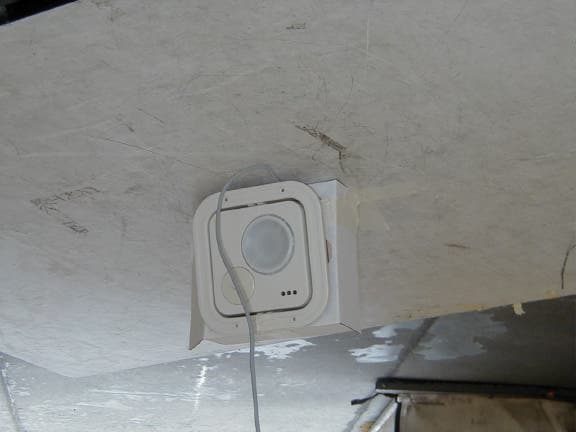
Overall View Top View Side View
ID Label/Location Info
FCC Label Location
Internal Photos
Cover Removed SN930 Board Battery Power Leads (Disconnected) (Detail) SN930 Tx Board Installed SN930 Tx Board Removed PCB Top View PCB Bottom View
Operational Description
Theory of operation : SN921 The SN921-Repeater is designed to repeat messages, sent by specific transmitters, for reception by another SpreadNet repeater or receiver. The repeat process is described as following: -The SN921’s re-receiver receives messages sent by many transmitters. These messages may or may not belong to the security system or the repeater. -The SN921’s re-receiver filters out all messages which have a property code that is greater than it’s programmed property code. -The SN921’s re-receiver retains valid messages (those with proper property code) in the buffer. -The SN921’s re-receiver then converts valid messages into data mode commands, and sends the commands to its re-transmitter through a serial interface. -Upon receiving the valid messages from re-receiver, the re-transmitter re-formats the message and re-transmits the message using the re-transmitter’s property code. POWER SUPPLY: The power supply used is an off-the-shelf item. A class 2, 16.5 VAC, 50/60 Hz, 40 VA transformer provides power to the power supply. The power supply provides a 12VDC 1 Amp regulated output. The power supply also has a charger used to charge a 12VDC, 6.5 AH back-up battery. If AC power is off, this back up battery supplies power to the repeater for 18 hours. The 12VDC output is connected to SN921 re-receiver TB-1 pins 7 and 8. RECEIVER OPERATION: The SN921 Repeater is a dual down conversion super-heterodyne spread spectrum receiver operating in the 900Mhz ISM band. RF Section: The Repeater is tuned for a carrier frequency of 923.58Mhz entering in at either Ant A or Ant B. The antennas are positioned orthogonally to each other to achieve polar diversity and are enabled on and off until final synchronization is achieved and then the higher power antenna is selected. The 923.58Mhz signal passes through a series of wide-band filters after being amplified by the LNA (Low Noise Amplifier) stage. The first down-conversion is accomplished by mixing the first LO1 signal of 684.66Mhz with the incoming 923.58Mhz received signal to achieve a 238.92Mhz IF signal after filtering out the positive image frequency. After filtering, the 238.92Mhz signal is mixed with the second LO2 of 228.22Mhz to achieve the final IF of 10.7Mhz. The 10.7Mhz spread spectrum IF signal is fed into the 1496 decorrelator IC where the spread spectrum code sequence is mixed with the received 10.7Mhz signal to de-spread the signal. The de-spread signal is passed through a series of 10.7Mhz band-pass ceramic filters and fed into the NE604 IF amplifier. Signal is then taken from the NE604 RSSI (received signal strength indicator) output. Digital Section: Three micro-controllers are used to provide parallel operation between processing incoming RF signals and outgoing serial data. All CPU’s are interfaced using a parallel bus configuration. The Master CPU controls all functions of the data acquisition and synchronization. The Slave CPU is responsible for the spread spectrum code generation, antenna switching, and sample and hold control. The Communications CPU is the interface buffer between the Master CPU and the external interface which is a Host or its Transmitter. It manages the FIFO buffering and CRC detection/correction and formats data specific to do proper tasks. The RSSI signal feeds a sample and hold circuit controlled by the Master and Slave CPU’s. The sampled RSSI signal feeds into the Master CPU A/D where the data is processed. During synchronization, the Master CPU slides the code sequence chip by chip until it receives a hit from a transmitter. The Master CPU then locks on to the signal and achieves a fine search by controlling the clock of the Slave CPU to purposely shift the code sequence in increments of 1/8 of a chip. After the complete message is received, the Master CPU transfers the message to the COM CPU where it is checked for validity, compressed, and stored in the COM CPU’s internal FIFO buffer. When a poll request arrives from an external device, the message is transferred if it is operates 911 mode. In the repeater mode, the COM CPU manages and analyzes all incoming messages and depending on the programmed parameters, it sends the messages to its transmitter to be repeated. Transmitter Operation: The SN-921 transmitter section has two primary sections, one digital and one RF. The digital section, in summary, provides all transmitter timing, RF control, and data message organization. Most of these functions are performed by the microprocessor. Several functions external to the microprocessor provide power supply regulation, battery low detection, alarm signal input conditioning, and non-volatile transmitter setup information that the microprocessor accesses during the transmit interval to construct its transmitted data message. A low power wake up timer also connects to the microproccessor and will reset the microprocessor if a lock up condition exists. The transmit sequence is initiated when data mode commands are sent by the receiver to the transmitter via a serial interface. The tranmitter microprocessor then re-formats the message and begins the tranmit sequence.
RF Exposure Info
Document 6415-01, Rev. 0 FCC ID: ?fccid FCC Certification Test Report Washington Laboratories, Ltd August 2001 Page 1 of 2 RF Exposure Calculation per FCC §2.1091 for IntelliSense C2DLWSH-21-SR August 28, 2001 Prepared for: IntelliSense 625 Coolidge Drive Folsom, CA 95630 Prepared By: Washington Laboratories, Ltd. 7560 Lindbergh Drive Gaithersburg, Maryland 20879 Document 6415-01, Rev. 0 FCC ID: ?fccid FCC Certification Test Report Washington Laboratories, Ltd August 2001 Page 2 of 2 1. Radiofrequency radiation evaluation exposure (§2.1091) FCC §2.1091 calls out the criteria for evaluation of radiofrequency exposure. The SN921 is a fixed device and is not to be moved once installed. Per §2.1091(c), the requirements for evaluation of RF exposure do not apply to this equipment. If the device were classified as a mobile device, per 2.1091(c), mobile devices that operate at frequencies in excess of 1.5 GHz and whose ERP is less than 3 watts are excluded from routine environmental evaluation. The operational frequency of the SN921 Spread Spectrum Transmitter is 923.58 MHz The ERP for the SN921 transmitter is calculated as follows: Effective Radiated Power, ERP = PtGt Power Density, S = E 2 /Zo S = (PtGt)/4πr 2 PtGt = S X 4πr 2 From measurement, the output power of the transmitter is 50.1 mW. The PCB antenna is designed to be omnidirectional and has a nominal gain of 0dBi or 1. Thus, PtGt = 50.1 X 10 -3 * 1 And PtGt = 50.1 mW This is well below the 3 Watt limit set by the FCC in 2.1091(c).
Test Report
Document 6395-01, Rev. 0 FCC Certification Test Report Washington Laboratories, Ltd August 2001 FCC Certification Test Report for IntelliSense C2DLWSH-21-SR August 24, 2001 Prepared for: IntelliSense 625 Coolidge Drive Folsom, CA 95630 Prepared By: Washington Laboratories, Ltd. 7560 Lindbergh Drive Gaithersburg, Maryland 20879 FCC Certification Test Report Document 6395-01, Rev. 0 FCC Certification Test Report Washington Laboratories, Ltd August 2001 FCC Certification Test Program FCC Certification Test Report for the IntelliSense SN921 Direct Sequence Spread Spectrum Transmitter C2DLWSH-21-SR August 10, 2001 WLL JOB# 6395 Prepared by: Brian J. Dettling Documentation Specialist Reviewed by: Gregory M. Snyder Chief EMC Engineer Document 6395-01, Rev. 0 FCC ID: C2DLWSH-21-SR FCC Certification Test Report Washington Laboratories, Ltd August 2001 ii Abstract This report has been prepared on behalf of IntelliSense to support the attached Application for Equipment Authorization. The test report and application are submitted for an Intentional Radiator under Part 15.247 of the FCC Rules and Regulations. This Federal Communication Commission (FCC) Certification Test Report documents the test configuration and test results for an IntelliSense SN921 Direct Sequence Spread Spectrum Transmitter. Testing was performed on an Open Area Test Site (OATS) of Washington Laboratories, Ltd, 7560 Lindbergh Drive, Gaithersburg, MD 20879. Site description and site attenuation data have been placed on file with the FCC's Sampling and Measurements Branch at the FCC laboratory in Columbia, MD. Washington Laboratories, Ltd. has been accepted by the FCC and approved by NIST NVLAP (NVLAP Lab Code: 200066-0) as an independent FCC test laboratory. The IntelliSense SN921 Direct Sequence Spread Spectrum Transmitter complies with the limits for an Intentional Radiator device under Part 15.247 of the FCC Rules and Regulations. Document 6395-01, Rev. 0 FCC ID: C2DLWSH-21-SR FCC Certification Test Report Washington Laboratories, Ltd August 2001 iii Table of Contents Abstract......................................................................................................ii 1 Introduction...................................................................................................................1 1.1 Compliance Statement............................................................................................1 1.2 Test Scope............................................................................................................1 1.3 Contract Information..............................................................................................1 1.4 Test Dates.............................................................................................................1 1.5 Test and Support Personnel....................................................................................1 1.6 Abbreviations.........................................................................................................1 2 Equipment Under Test....................................................................................................2 2.1 EUT Identification & Description............................................................................2 2.2 Test Configuration..................................................................................................3 2.3 Testing Algorithm...................................................................................................3 2.4 Test Location.........................................................................................................3 2.5 Measurements........................................................................................................3 2.5.1 References.....................................................................................................3 2.6 Measurement Uncertainty.......................................................................................4 3 Test Equipment..............................................................................................................4 4 Test Results...................................................................................................................5 4.1 Duty Cycle Correction...........................................................................................5 4.2 RF Power Output: (FCC Part §15.247(b)(1))........................................................5 4.3 Bandwidth: (FCC Part §15.247(a)(2))...................................................................5 4.4 Spurious Emissions at Antenna Terminals (FCC Part §15.247(c))...........................8 4.5 Power Spectral Density: (FCC Part §15.247(d))..................................................17 4.6 Radiated Spurious Emissions; Restricted Bands: (FCC Part §15.205)...................19 4.6.1 Test Procedure..........................................................................................19 4.7 AC Powerline Conducted Emissions: (FCC Part §15.207)...................................24 List of Tables Table 1. Device Summary....................................................................................................3 Table 2: Test Equipment List...............................................................................................4 Table 3. RF Power Output...................................................................................................5 Table 4: Radiated Emission Test Data................................................................................20 Table 5: Conducted Emissions Test Data; 15.207..............................................................26 Document 6395-01, Rev. 0 FCC ID: C2DLWSH-21-SR FCC Certification Test Report Washington Laboratories, Ltd August 2001 iv List of Figures Figure 1. Occupied Bandwidth.............................................................................................7 Figure 2. Conducted Spurious Emissions,…
Text truncated - open the document above for the full version.
Test Report
FCC Certification Test Report Addendum for FCC ID: C2DLWSH-21-SR The following questions were raised during the review of the FCC certification filing for FCC ID: C2DLWSH-21-SR. Responses to the questions and additional data have been submitted within this addendum. 1) In compliance with 15.35 of the FCC rules, data taken above 1000 MHz must be tested using an average detector utilizing a Resolution bandwidth of 1 MHz. Please provide the corresponding data using the average detector and information stating that the appropriate bandwidth for measurements above 1000 MHz were used. Reply: The output from the antenna was connected, via a preamplifier, to the input of the spectrum analyzer. The detector function was set to quasi-peak or peak, as appropriate. The measurement bandwidth on the spectrum analyzer system was set to at least 120 kHz, with all post-detector filtering no less than 10 times the measurement bandwidth. For measurements above 1 GHz, the measurement bandwidth was set to 1MHz. Average data, using the duty cycle correction, are listed in the original test report. 2) Please also provide corresponding data demonstrating that the difference between the peak and average measurement for the restricted bands is less the 20dB above the average readings. Reply: Peak emissions data above 1 GHz are recorded in Table 1A of this addendum. As the emission is pulsed, peak emission levels were measured and corrected using the duty cycle correction as described in Section 4.1 of the original test report. The original test reports has data corrected using the duty cycle correction and then compared to the average limit. Table 1A - FCC 15.247(c) 3M Radiated Emissions Data Peak Measurements Above 1GHz CLIENT: Intellisense MODEL NO: SN921-REPEATER TYPE/PART: Spread Spectrum TX DATE: 7/5/2001 BY: Greg Snyder JOB #: 6395 Tx FREQUENCY: 923.58 Mhz nf= Noise Floor ORIENTATION: X=Flat (Ant. @90 degree) Frequency Polarity Azimuth Antenna SA Level AFc E-Field E-Field Limit Margin Height (PEAK) MHz H/V Degree m dBuV dB/m dBuV/m uV/m uV/m dB 1216.80 V 135.00 1.0 68.50 -10.9 57.6 756.4 5000.0 -16.4 1216.80 H 135.00 1.0 63.0 -10.9 52.1 401.6 5000.0 -21.9 1231.44 V 135.00 1.0 81.30 -10.8 70.5 3345.5 5000.0 -3.5 1231.44 H 135.00 1.0 76.3 -10.8 65.5 1881.3 5000.0 -8.5 1539.30 V 90.00 1.0 60.50 -8.7 51.8 390.0 5000.0 -22.2 1539.30 H 180.00 1.0 59.8 -8.7 51.2 361.0 5000.0 -22.8 2500.00 H 225.00 1.0 48.5 -5.2 43.3 145.7 5000.0 -30.7 2770.83 V 112.50 1.0 62.83 -4.8 58.0 796.6 5000.0 -16.0 2770.83 H 225.00 1.0 56.2 -4.8 51.4 371.3 5000.0 -22.6 3694.44 V 180.00 1.0 56.70 -3.6 53.1 450.9 5000.0 -20.9 3694.44 H 135.00 1.0 50.8 -3.6 47.2 228.6 5000.0 -26.8 4603.62 V 0.00 1.0 45.50 -2.7 42.8 137.9 5000.0 -31.2 nf 4603.62 H 225.00 1.0 46.8 -2.7 44.1 160.1 5000.0 -29.9 nf 4618.05 V 180.00 1.0 47.20 -2.7 44.5 167.9 5000.0 -29.5 4618.05 H 225.00 1.0 48.8 -2.7 46.1 201.9 5000.0 -27.9 4926.80 V 180.00 1.0 51.20 -2.4 48.8 274.5 5000.0 -25.2 4926.80 H 135.00 1.0 53.7 -2.4 51.3 366.0 5000.0 -22.7 5406.00 V 0.00 1.0 45.40 -2.0 43.4 147.1 5000.0 -30.6 nf 5406.00 H 0.00 1.0 45.4 -2.0 43.4 147.1 5000.0 -30.6 7388.64 V 0.00 1.0 45.50 2.2 47.7 242.7 5000.0 -26.3 nf 7388.64 H 180.00 1.0 46.0 2.2 48.2 257.0 5000.0 -25.8 nf 8312.22 V 0.00 1.0 45.20 2.2 47.4 234.4 5000.0 -26.6 nf 8312.22 H 0.00 1.0 45.6 2.2 47.8 245.5 5000.0 -26.2 nf 9236.40 V 0.00 1.0 46.20 2.5 48.7 272.2 5000.0 -25.3 nf 9236.40 H 180.00 1.0 46.0 2.5 48.5 266.0 5000.0 -25.5 nf ORIENTATION: Y=Standing Up/Vertical Mount Frequency Polarity Azimuth Antenna SA Level AFc E-Field E-Field Limit Margin Height (PEAK) MHz H/V Degree m dBuV dB/m dBuV/m uV/m uV/m dB 1216.80 V 22.00 1.0 72.30 -10.9 61.4 1171.5 5000.0 -12.6 1216.80 H 90.00 1.0 62.20 -10.9 51.3 71.4 5000.0 -22.7 1231.44 V 22.00 1.0 81.20 -10.8 70.4 3307.2 5000.0 -3.6 1231.44 H 90.00 1.0 78.50 -10.8 67.7 2423.6 5000.0 -6.3 1539.30 V 0.00 1.0 54.60 -8.7 45.9 197.7 5000.0 -28.1 1539.30 H 157.50 1.0 61.20 -8.7 52.5 422.7 5000.0 -21.5 2770.83 V 180.00 1.0 62.20 -4.8 57.4 740.9 5000.0 -16.6 2770.83 H 135.00 1.0 68.30 -4.8 63.5 1495.4 5000.0 -10.5 3694.44 V 225.00 1.0 59.80 -3.6 56.2 644.3 5000.0 -17.8 3694.44 H 315.00 1.0 56.00 -3.6 52.4 416.0 5000.0 -21.6 4603.62 V 180.00 1.0 44.80 -2.7 42.1 127.2 5000.0 -31.9 nf 4603.62 H 315.00 1.0 46.00 -2.7 43.3 146.0 5000.0 -30.7 nf 4618.05 V 157.50 1.0 49.70 -2.7 47.0 223.9 5000.0 -27.0 4618.05 H 135.00 1.0 48.40 -2.7 45.7 192.8 5000.0 -28.3 4925.80 V 180.00 1.0 50.70 -2.4 48.3 259.1 5000.0 -25.7 4926.80 H 135.00 1.0 50.50 -2.4 48.1 253.2 5000.0 -25.9 5541.36 V 180.00 1.0 42.70 -1.9 40.8 109.1 5000.0 -33.2 nf 5541.36 H 315.00 1.0 45.80 -1.9 43.9 155.9 5000.0 -30.1 nf 7388.64 V 90.00 1.0 45.00 2.2 47.2 229.1 5000.0 -26.8 nf 7388.64 H 202.50 1.0 47.0 2.2 49.2 288.4 5000.0 -24.8 nf 8312.22 V 0.00 1.0 46.50 2.2 48.7 272.3 5000.0 -25.3 nf 8312.22 H 0.00 1.0 46.6 2.2 48.8 275.4 5000.0 -25.2 nf 9236.40 V 0.00 1.0 46.60 2.5 49.1 285.0 5000.0 -24.9 nf 9236.40 H 0.00 1.0 45.80 2.5 48.3 260.0 5000.0 -25.7 nf ORIENTATION: Z=Antenna Parallel to Rx Antenna Frequency Polarity Azimuth Antenna SA Level AFc E-Field E-Field Limit Margin Height (PEAK) MHz H/V Degree m dBuV dB/m dBuV/m uV/m uV/m dB 1216.80 V 315.00 1.0 68.00 -10.9 57.1 714.1 5000.0 -16.9 1216.80 H 90.00 1.0 62.30 -10.9 51.4 370.5 5000.0 -22.6 1231.44 V 45.00 1.0 81.30 -10.8 70.5 3345.5 5000.0 -3.5 1231.44 H 90.00 1.0 76.80 -10.8 66.0 1992.8 5000.0 -8.0 1539.30 V 315.00 1.0 60.00 -8.7 51.3 368.2 5000.0 -22.7 1539.30 H 315.00 1.0 56.50 -8.7 47.8 246.1 5000.0 -26.2 2770.83 V 270.00 1.0 63.30 -4.8 58.5 840.9 5000.0 -15.5 2770.83 H 0.00 1.0 61.50 -4.8 56.7 683.5 5000.0 -17.3 3694.44 V 315.00 1.0 52.80 -3.6 49.2 287.8 5000.0 -24.8 3694.44 H 225.00 1.0 56.20 -3.6 52.6 425.7 5000.0 -21.4 4603.62 V 315.00 1.0 45.60 -2.7 42.9 139.5 5000.0 -31.1 nf 4603.62 H 338.00 1.0 45.30 -2.7 42.6 134.7 5000.0 -31.4 nf 4618.05 V 270.00 1.0 48.00 -2.7 45.3 184.1 5000.0 -28.7 4618.05 H 180.00 1.0 46.80 -2.7 44.1 160.4 5000.0 -29.9 4926.80 V 90.00 1.0 46.30 -2.4 43…
Text truncated - open the document above for the full version.
Test Setup Photos
Radiated Emissions Test Setup Front Back Conducted Emissions Test Setup Front Side
Contact Information
Applicant
Michael Antola(RF Compliance Engineer)
Technical Contact
Washington LaboratoriesGreg Snyder
[email protected]301-417-0220
7560 Lindbergh Drive · Gaithersburg, Maryland · United States
Non-Technical Contact
Washington LaboratoriesBrian Dettling
[email protected]301-417-0220
Test Firm
Washington Laboratories, Ltd.Michael Violette
Technical Specifications
| # | Rule Parts | Frequency Range | Power Output |
|---|---|---|---|
| 1 | 15C | 923.58 MHz - 923.58 MHz | 50.00 mW |
Other Applications from Ademco Inc.
C2DDUALTEC7360
Mar 18, 2004Microwave/Passive PIR Intrusion Detection
Equipment Class
FDS - Part 15 Field Disturbance Sensor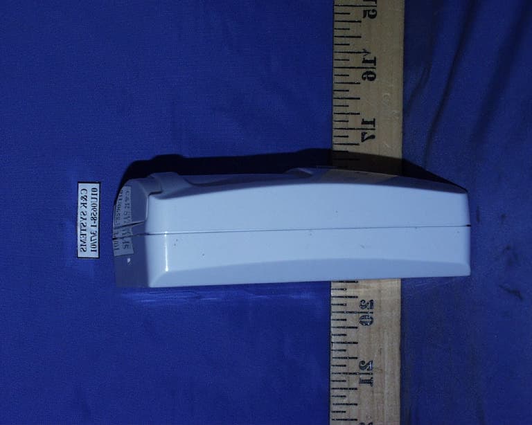
C2D7KULP
May 21, 2001Microwave/Passive IR Monitor Detector
Equipment Class
FDS - Part 15 Field Disturbance SensorC2DLWSN-61-KF
Sep 02, 1997R/C Alarm System Transmitter Maximum output power: 11.6 mW
Equipment Class
DSS - Part 15 Spread Spectrum TransmitterC2DBG90KKDM
Jun 05, 1997FDS - Part 15 Field Disturbance Sensor
Equipment Class
FDS - Part 15 Field Disturbance SensorC2DBG200KKDM
Jun 05, 1997FDS - Part 15 Field Disturbance Sensor
Equipment Class
FDS - Part 15 Field Disturbance Sensor