C2R5054DX100Communications Receiver
Ranger Electronic Communications Inc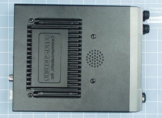
Click to zoom
Application Details
- Equipment Class
- CXX - Communications Rcvr for use w/ licensed Tx and CBs
- Date of Grant
- Apr 17, 2002
- Application Purpose
- Original Equipment
- Date of Application
- Apr 17, 2002
- Equipment Note
- Communications Receiver
- Frequency Range
- 50.00000000 - 54.00000000
- Country
- Taiwan
Documents & Files
Document Text
Text extracted from the exhibit documents filed with the FCC. Open a document above to read the original.
Users Manual
AM/FM/SSB/CW 6 Meter Amateur Mobile Transceiver Owner's Manual RCI-5054 DX / RCI-5054 DX -100 - 1 - Table of Contents PAGE Chapter 1 Specifications ....................................................... 2 Chapter 2 Introduction .......................................................... 3 Unpacking ........................................................................... 3 Chapter 3 Installation ............................................................ 4 Transceiver Mounting ........................................................... 4 Power Connection ............................................................... 4 Chapter 4 Operation .............................................................. 5 Front Panel .......................................................................... 5 Rear Panel ........................................................................... 9 Microphone ......................................................................... 10 Frequency Selection ............................................................. 11 Mode Selection .................................................................... 12 RF Power Control ................................................................. 12 Chapter 5 Programming ........................................................ 13 Receive Scanning ............................................................... 13 Split Function ....................................................................... 13 Memory Function ................................................................. 13 Memory Channel Scanning ................................................... 14 Metering .............................................................................. 14 Chapter 6 Frequency Si 14 All-Frequency Scanning ........................................................ 15 Memory Scanning ................................................................ 16 Chapter 7 Offset Frequency Oi 17 Memo .................................................................................... 18 LIMITED WARRANTY ............................................. Inside Back Cover - 2 - Chapter 1 Specifications GENERAL Model RCI-5054DX RCI-5054DX-100 Frequency Range : 50.000 ~ 54.000 MHz 50.000 ~ 54.000 MHz Tuning Steps 100 Hz, 1 KHz, 10 KHz, 100 KHz, 1 MHz 100 Hz, 1 KHz, 10 KHz, 100 KHz, 1 MHz Emission USB, LSB, CW, AM, FM USB, LSB, CW, AM, FM Frequency Control Phase-Lock-Loop Synthesizer Phase-Lock-Loop Synthesizer Frequency Tolerance 0.005% 0.005% Frequency Stability 0.001% 0.001% Operating Temperature Range -10 O C to +50 O C -10 O C to +50 O C Antenna Impedance 50 ohm 50 ohm Microphone Plug-In (6-Pin), 400 Ω Dynamic PTT Plug-In (6-Pin), 400 Ω Dynamic PTT Meter Function RF Output, RX Receive Signal Strength, SWR RF Output, RX Receive Signal Strength, SWR Input Voltage 13.8 V DC 13.8 V DC Dimensions 7 3/4" (W) x 10 3/4" (D) x 2 3/8" (H) 7 3/4" (W) x 9 3/4" (D) x 2 7/8" (H) Weight 4 lb. 3 oz. 5 lb. 13 oz. TRANSMITTER RF Power Output 25W : USB/LSB Peak Power 10W : CW/AM/FM 100W : USB/LSB Peak Power 50W : CW/AM/FM RF Transmit Modes USB, LSB, CW, AM, FM USB, LSB, CW, AM, FM Antenna Connector UHF Type, 50 Ω UHF Type, 50 Ω Modulation 16F3, A3E, J3E, A1A 16F3, A3E, J3E, A1A Spurious Emissions >60 dB >60 dB Carrier Suppression -50 dB -50 dB RECEIVER Sensitivity AM/CW : 0.5 uV for 10dB Sinad FM : 0.25uV for 12dB Sinad USB/LSB : 0.15uV for 10dB Sinad AM/CW : 0.5 uV for 10dB Sinad FM : 0.25uV for 12dB Sinad USB/LSB : 0.15uV for 10dB Sinad Image Rejection Ratio -65 dB -65 dB AGC Figure of Merit SSB/C W/AM : 80dB at 50mV for a 10dB change in Audio Output SSB/CW/AM : 80dB at 50mV for a 10dB change in Audio Output Audio Power Output 2.5W 2.5W ( SPECIFICATIONS SUBJECT TO CHANGE WITHOUT NOTICE ) - 3 - Chapter 2 Introduction Congratulations on your purc hase of an RCI-5054DX/5054DX-100 6 meter amateur radio. Your RC I-5054DX/5054DX-100 is designed to provide trouble-free service and state-of-the-art communications in the 6 meter band. Please read this manual thoroughly to ensure proper performance. Unpacking The following items are includ ed with our RCI-5054DX/5054DX-100. Carefully remove and examine all mate rials from the packing carton. If any items are missing or appear da maged, please contact your dealer immediately. Each unit should include: (1) RCI-5054DX/5054DX-100 Transceiver (2) Dynamic Microphone with remote frequency adjustment switches (3) Power Cord (4) Mounting Bracket & Hardware (5) Installation Hardware (6) Owner's Manual (7) Warranty Registration Card It is recommended that you save the packing materials for future storage or shipping. IMPORTANT To operate this radio, you must possess and amateur radio operator's license issued by the FCC. Oper ation of this unit without proper licensing is ILLEGAL and can result in severe penalties. NOTE The manufacturer is not responsible for any radio or TV interference caused by unauthorized modifications to this equipment. Such modifications could void the user’s au thority to operate this equipment. - 4 - Chapter 3 Installation The RCI-5054DX/5054DX-100 is easy to install. All necessary parts (less the antenna and coax cable) have been included to facilitate installation. Transceiver Mounting Choose a suitable location for the transceiver that will allow easy access to the front panel as well as proper air circulation to the back of the unit. If you are installing the unit in a vehicl e, attach the mounting bracket first, then attach the transceiver to the mounting bracket using the hardware provided. Before making any electrical connection, ensure that the transceiver is turned off and the vehicle's battery is disconnected. Power Connection The transceiver operates off of any 12 to 13.8 VDC source. Beware of voltage drops caused by operating fr om Cigarette Lighter Plugs or long DC wire runs. Sometimes it is best to connect direct to the battery for best RF output and Tx audio quality If an AC power supply is u…
Text truncated - open the document above for the full version.
External Photos
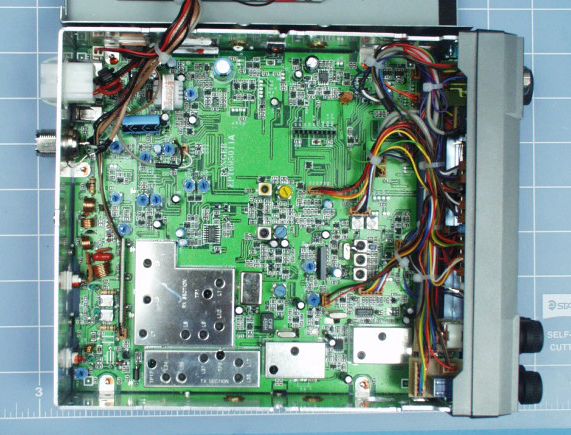
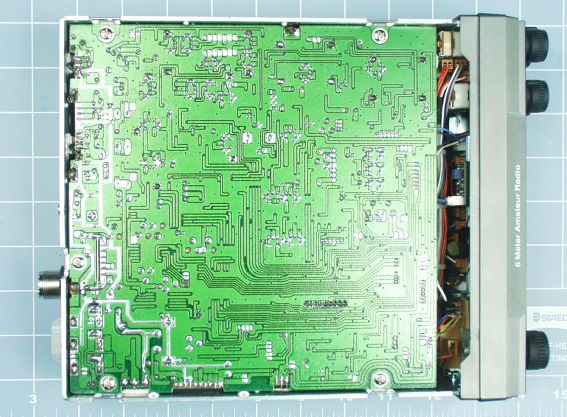
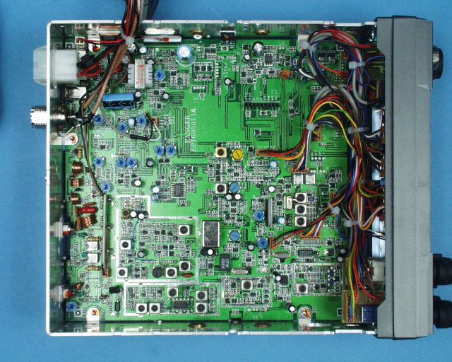
Front View Top View Left Side View Bottom View Right Side View Back View
Test Report
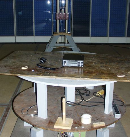
ENGINEERING STATEMENT In Regard to Measurements on Model No. RCI-5054DX-100 RANGER COMMUNICATIONS INC. FCC ID: C2R5054DX100 A. INTRODUCTION Hyak Laboratories, Inc. has been authorized by Ranger Communications Inc. to perform measurements on a receiver to determine compliance with FCC rules, Part 15, Para. 15.109. The receiver operates in the 50 - 54 MHz band and is in- tended for use as a 6 meter amateur radio receiver. B. DESCRIPTION OF RECEIVER The device incorporates a dual conversion superheterodyne design. The following information is supplied as requested in FCC Bulletin OCE 24: 1. Service in which the receiver will be used: Part 15. 2. Function of receiver: Amateur Radio. 3. Tuning range: 50 - 54 MHz. 4. IFs used: 10.695 MHz; 455 kHz 5. Fundamental frequency of all oscillators in the receiver: 1 st L.O.:(F c -10.695) MHz 2 nd L.O.: 10.24 MHz C. DESCRIPTION OF MEASUREMENT PROCEDURE: RADIATED EMISSIONS Measurements of receiver radiation field strength were made using ANSI 63.4 (1992) as the basic procedure. Measurements were made with 3 meter spacing between the receiver under test and the test equipment antenna. The receiver was operated with an external antenna. The receiver under test was placed on a rotatable table 80 cm in height. Measurement of field strength was made through use of a TEK 494P spectrum analyzer in conjunction with Singer DM-105A series calibrated dipoles. The receiver was tuned to low and high channels. For each spurious emission identified between 30 to 2000 MHz, the test sample was rotated for maximum pickup, the test antenna varied in elevation, and the test antenna polarization shifted between horizontal to vertical in order to maximize observed signals. D. REPORT OF RADIATED EMISSIONS All signals observed from 30 to 2000 MHz were more than 20 dB below the limits of paragraph 15.109 of the FCC Rules. E. DESCRIPTION OF MEASUREMENT PROCEDURE; AC-LINE CONDUCTED Not applicable; operates from vehicle 13.8 V supply. F. STATEMENT Technical test data are from tests performed by me or under my supervision. My qualifications are a matter of record with the Federal Communications Commission. I personally attest to the accuracy of the test data submitted as a part of this engineering statement. __________________________________ Rowland S. Johnson Dated: April 2, 2002
Contact Information
Applicant
Susan Chiu
Test Firm
Carl T. Jones CorporationCarl Jones
Technical Specifications
| # | Rule Parts | Frequency Range | Power Output |
|---|---|---|---|
| 1 | 15B | 50 MHz - 54 MHz | - |
Other Applications from Ranger Electronic Communications Inc
C2R-TRE-SBMD
Jun 27, 2011CB TRANSCEIVER
Equipment Class
TNB - Licensed Non-Broadcast Station Transmitter
C2R-PPR-125
Feb 25, 2008CB TRANSCEIVER
Equipment Class
TNB - Licensed Non-Broadcast Station Transmitter
C2R5054DX
Jun 18, 2001Communications Receiver
Equipment Class
CXX - Communications Rcvr for use w/ licensed Tx and CBs
C2R-DX-2547
Jul 08, 1999CB Transceiver
Equipment Class
TNB - Licensed Non-Broadcast Station Transmitter
C2R-DX-2537
Jul 08, 1999CXX - Communications Rcvr for use w/ licensed Tx and CBs
Equipment Class
CXX - Communications Rcvr for use w/ licensed Tx and CBs