CCRXP106WBluetooth Speaker
Sam Ash Music Corporation
Click to zoom
Application Details
- Equipment Class
- DSS - Part 15 Spread Spectrum Transmitter
- Date of Grant
- May 20, 2020
- Application Purpose
- Original Equipment
- Date of Application
- May 20, 2020
- Equipment Note
- Bluetooth Speaker
- Frequency Range
- 2402.00000000 - 2480.00000000
- Company
- Sam Ash Music Corporation
- Country
- United States
Documents & Files
Document Text
Text extracted from the exhibit documents filed with the FCC. Open a document above to read the original.
Users Manual
Owner's Manual E PEDITION XP 106 PORTABLE PA WITH 2 Copyright 2017 v3.0 Samson Technologies Corp. 278-B Duffy Avenue Hicksville, NY 11801 Phone: 1-800-3-SAMSON (1-800-372-6766) www.samsontech.com The Bluetooth® word mark and logos are registered trademarks owned by Bluetooth SIG, Inc. and any use of such marks by Samson Technologies is under license. Other trademarks and trade names are those of their respective owners.” 3 XP106 • Portable PA System Important Safety Information WARNING: TO REDUCE THE RISK OF ELECTRIC SHOCK, DO NOT REMOVE COVER (OR BACK) AS THERE ARE NO USER-SERVICEABLE PARTS INSIDE. REFER SERVICING TO QUALIFIED SERVICE PERSONNEL. This lightning flash with arrowhead symbol within an equilateral triangle is intended to alert the user to the presence of non-insulated “danger- ous voltage” within the product’s enclosure that may be of sufficient magnitude to constitute a risk of electric shock. The exclamation point within an equilateral triangle is intended to alert the user to the presence of important operating and maintenance in- structions in the literature accompanying the appliance. AVIS RISQUE DE CHOC ÉLECTRONIQUE - NE PAS OUVRIR If you want to dispose this product, do not mix it with general household waste. There is a separate collection system for used electronic products in accordance with legislation that requires proper treatment, recovery and recycling. Private household in the 28 member states of the EU, in Switzerland and Norway may return their used electronic products free of charge to designated collection facilities or to a retailer (if you purchase a similar new one). For Countries not mentioned above, please contact your local authorities for a correct method of disposal. By doing so you will ensure that your disposed product undergoes the necessary treatment, recovery and recycling and thus prevent potential negative effects on the environment and human health. 4 1. Read these instructions. 2. Keep these instructions. 3. Heed all warnings. 4. Follow all instructions. 5. Do not use this apparatus near water. 6. Clean only with dry cloth. 7. Do not block any ventilation open- ings. Install in accordance with the manufacturer’s instructions. 8. Do not install near any heat sources such as radiators, heat registers, stoves, or other apparatus (including amplifiers) that produce heat. 9. Do not defeat the safety purpose of the polarized or grounding type plug. A polarized plug has two blades with one wider than the other. A grounding type plug has two blades and a third grounding prong. The wide blade or the third prong are provided for your safety. If the provided plug does not fit into your outlet, consult an electri- cian for replacement of the obsolete outlet. 10. Protect the power cord from being walked on or pinched particularly at the plugs, convenience receptacles, and at the point where they exit from the apparatus. 11. Only use attachments/accessories specified by the manufacturer. 12. Use only with the cart, stand, tripod, bracket, or table specified by the manufacturer, or sold with the ap- paratus. When a cart is used, use caution when moving the cart/appara- tus combination to avoid injury from tip-over. 13. Unplug the apparatus during lighten- ing storms or when unused for long periods of time. 14. Refer all servicing to qualified personnel. Service is required when the apparatus has been damaged in any way, such as power supply cord or plug is damaged, liquid has been spilled or objects have fallen into the apparatus has been exposed to rain or moisture, does not operate normally, or has been dropped. 15. This appliance shall not be exposed to dripping or splashing water and that no object filled with liquid such as vases shall be placed on the ap- paratus. 16. Caution-to prevent electrical shock, match wide blade plug wide slot fully insert. 17. Please keep a good ventilation envi- ronment around the entire unit. 18. To prevent injury, this apparatus must be securely attached to the stand in accordance with the installation instructions. 19. WARNING: The battery (battery or batteries or battery pack) shall not be exposed to excessive heat such as sunshine, fire or the like. 20. CAUTION: Danger of explosion if bat- tery is incorrectly replaced. Replace only with the same or equivalent type. Important Safety Information 5 XP106 • Portable PA System Important Safety Information FCC Notice 1. This device complies with Part 15 of the FCC Rules. Operation is subject to the fol- lowing two conditions: (1) This device may not cause harmful interference. (2) This device must accept any interference received, including interference that may cause undesired operation. 2. Changes or modifications not expressly approved by the party responsible for compli- ance could void the user’s authority to operate the equipment. FCC Statement This equipment has been tested and found to comply with the limits for a Class B digi- tal device, pursuant to Part 15 of the FCC Rules. These limits are designed to provide reasonable protection against harmful interference in a residential installation. This equipment generates uses and can radiate radio frequency energy and, if not installed and used in accordance with the instructions, may cause harmful interference to radio communications. However, there is no guarantee that interference will not occur in a particular installation. If this equipment does cause harmful interference to radio or television reception, which can be determined by turning the equipment off and on, the user is encouraged to try to correct the interference by one or more of the following measures: • Reorient or relocate the receiving antenna. • Increase the separation between the equipment and receiver. • Connect the equipment into an outlet on a circuit different from that to which the receiver is connected. • Consult the dealer or an experienced radio/TV technician for help. RF Warning Statement The device has been evaluated to meet general RF…
Text truncated - open the document above for the full version.
External Photos
External Photos M/N: XP106 External Photos M/N: XP106 External Photos M/N: XP106 External Photos M/N: XP106 External Photos M/N: XP106
ID Label/Location Info
Label Location
Internal Photos
Internal Photos M/N: XP106 Internal Photos M/N: XP106 Internal Photos M/N: XP106 Internal Photos M/N: XP106 Internal Photos M/N: XP106 Bluetooth Antenna Internal Photos M/N: XP106
RF Exposure Info
FCC ID: CCRXP106W EST Technology Co., Ltd Report No. ESTE-R2005030 Page 1 of 3 FCC RF EXPOSURE REPORT Sam Ash Music Corporation Bluetooth Speaker Model Number: XP106 FCC ID: CCRXP106W Prepared for: Sam Ash Music Corporation 262 Duffy Avenue, Hicksville, NY 11801 Prepared By: EST Technology Co., Ltd. Chilingxiang, Qishantou, Santun, Houjie, Dongguan, Guangdong, China Tel: 86-769-83081888-808 Report Number: ESTE-R2005030 Date of Test: Mar. 31~May. 09, 2020 Date of Report: May. 11, 2020 FCC ID: CCRXP106W EST Technology Co., Ltd Report No. ESTE-R2005030 Page 2 of 3 1. Applicable Standards FCC Part 2(Section 2.1093) FCC KD B447498 D01 General RF Exposure Guidance v06 2. Exposure Evaluation of Portable or Mobile Devices Human exposure to RF emissions from portable devices (47 CFR §2.1093), as defined by the FCC, must be evaluated with respect to the FCC-adopted limits for SAR. Evaluation of mobile devices, as defined by the FCC, may also be performed with respect to SAR limits, but in such cases it is usually simpler and more cost-effective to evaluate compliance with respect to field strength or power density limits. For certain devices that are designed to be used in both mobile and portable configurations similar to those described in 47 CFR §2.1091(d)(4), such as certain desktop phones and wireless modem modules, compliance for mobile configurations is also satisfied when the same device is evaluated for SAR compliance in portable configurations. SAR Test Exclusion Thresholds for 100 MHz – 6 GHz and ≤ 50 mm The 1-g and 10-g SAR test exclusion thresholds for 100 MHz to 6 GHz at test separation distances ≤ 50 mm are determined by [(max. power of channel, including tune-up tolerance, mW)/(min. test separation distance, mm)] · [√f(GHz)] ≤3.0 for 1-g SAR and ≤ 7.5 for 10-g extremity SAR where • f(GHz) is the RF channel transmit frequency in GHz • Power and distance are rounded to the nearest mW and mm before calculation • The result is rounded to one decimal place for comparison The test exclusions are applicable only when the minimum test separation distance is ≤ 50 mm and for transmission frequencies between 100 MHz and 6 GHz. When the minimum test separation distance is < 5 mm, a distance of 5 mm is applied to determine SAR test exclusion. FCC ID: CCRXP106W EST Technology Co., Ltd Report No. ESTE-R2005030 Page 3 of 3 3. Evaluation Results Mode CH Peak output Power (dBm) Peak output Power (mW) Target power (dBm) Results GFSK 2402 1.68 1.472 1±1 0.491 2441 2.01 1.589 2±1 0.623 2480 2.05 1.603 2±1 0.628 π/4-DQPSK 2402 2.21 1.663 2±1 0.618 2441 2.63 1.832 2±1 0.623 2480 2.65 1.841 2±1 0.628 BLE 2402 1.64 1.459 1±1 0.491 2440 1.98 1.578 1±1 0.495 2480 2.03 1.596 2±1 0.628 Note: 1. [(max. power of channel, including tune-up tolerance, mW)/(min. test separation distance, mm)] * [√f(GHz)] < 3.0. 2. SAR Test Exclusion Thresholds is 3.0 for separation distance 5mm. Therefore, SAR test is not required. End of Test Report
Test Report
FCC ID: CCRXP106W EST Technology Co., Ltd Report No.ESTE-R2005028 Page 1 of 75 FCC PART 15C TEST REPORT FOR CERTIFICATION On Behalf of Sam Ash Music Corporation Bluetooth Speaker Model Number: XP106 FCC ID: CCRXP106W Prepared for: Sam Ash Music Corporation 262 Duffy Avenue, Hicksville, NY 11801 Prepared By: EST Technology Co., Ltd. Chilingxiang, Qishantou, Santun, Houjie, Dongguan, Guangdong, China Tel: 86-769-83081888-808 Report Number: ESTE-R2005028 Date of Test: Mar. 31~May. 09, 2020 Date of Report: May. 11, 2020 FCC ID: CCRXP106W EST Technology Co., Ltd Report No.ESTE-R2005028 Page 2 of 75 TABLE OF CONTENTS Description Page TEST REPORT VERIFICATION ........................................................................................................................ 3 1. GENERAL INFORMATION ................................................................................................................. 5 1.1. Description of Device (EUT) ........................................................................................................... 5 1.2. Antenna Information ........................................................................................................................ 5 2. SUMMARY OF TEST ......................................................................................................................... 6 2.1. Summary of test result ...................................................................................................................... 6 2.2. Test Facilities .................................................................................................................................... 7 2.3. Measurement uncertainty ................................................................................................................. 8 2.4. Assistant equipment used for test ..................................................................................................... 8 2.5. Block Diagram .................................................................................................................................. 8 2.6. Test mode ......................................................................................................................................... 9 2.7. Channel List .................................................................................................................................... 10 2.8. Power Setting of Test Software ...................................................................................................... 10 2.9. Test Equipmen ................................................................................................................................ 11 3. MAXIMUM PEAK OUTPUT POWER ................................................................................................. 12 3.1. Limit ............................................................................................................................................... 12 3.2. Test Setup ....................................................................................................................................... 12 3.3. Spectrum Analyzer Setting ............................................................................................................. 12 3.4. Test Procedure ................................................................................................................................ 12 3.5. Test Result ...................................................................................................................................... 13 4. 20 DB BANDWIDTH ...................................................................................................................... 17 4.1. Limit ............................................................................................................................................... 17 4.2. Test Setup ....................................................................................................................................... 17 4.3. Spectrum Analyzer Setting ............................................................................................................. 17 4.4. Test Procedure ................................................................................................................................ 17 4.5. Test Result ...................................................................................................................................... 18 5. CARRIER FREQUENCY SEPARATION .............................................................................................. 22 5.1. Limit ............................................................................................................................................... 22 5.2. Test Setup ....................................................................................................................................... 22 5.3. Spectrum Analyzer Setting ............................................................................................................. 22 5.4. Test Procedure ................................................................................................................................ 22 5.5. Test Result ...................................................................................................................................... 23 6. NUMBER OF HOPPING CHANNEL .................................................................................................. 27 6.1. Limit ............................................................................................................................................... 27 6.2. Test Setup ....................................................................................................................................... 27 6.3. Spectrum Analyzer Setting ............................................................................................................. 27 6.4. Test Proce…
Text truncated - open the document above for the full version.
Test Setup Photos
Conducted Test Radiated Test (30-1000 MHz) Radiated Test (Above 1GHz)
Contact Information
Applicant
Don Albanese
Test Firm
EST Technology Co., Ltd.Iceman Hu
[email protected]+86 0769-83081888
Technical Specifications
| # | Rule Parts | Frequency Range | Power Output |
|---|---|---|---|
| 1 | 15C | 2.40 GHz - 2.48 GHz | 1.84 mW |
Other Applications from Sam Ash Music Corporation
CCRCBXD2
Jan 11, 2024TRANSMITTER
Equipment Class
PUT - Part 15 Unlicensed PCS portable Tx worn on body
CCRCHXD2
Jan 11, 2024TRANSMITTER
Equipment Class
PUF - Part 15 Unlicensed PCS portable Tx held to face
CCRET100
Jan 09, 2024ET100 UHF Transmitter
Equipment Class
TLD - Licensed LPAS Device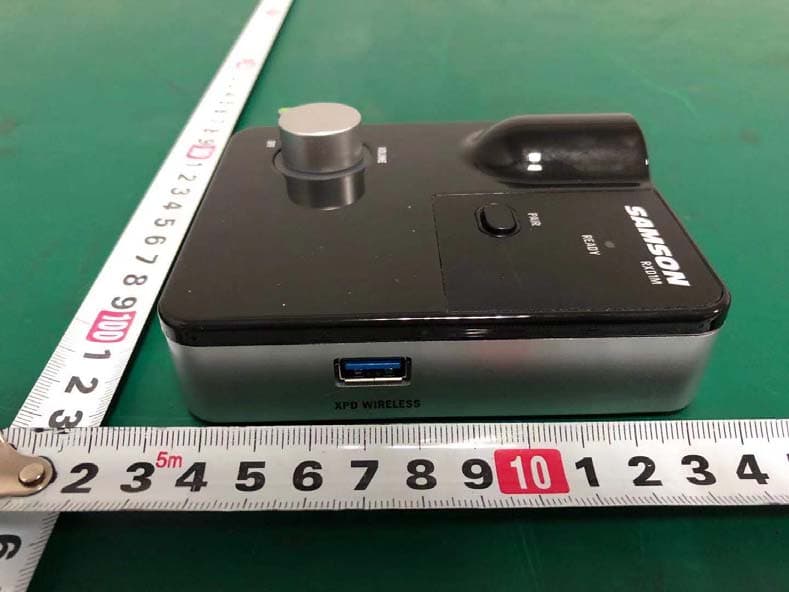
CCRRXD1M
Mar 18, 20202.4G Wireless microphone Receiver
Equipment Class
DXX - Part 15 Low Power Communication Device Transmitter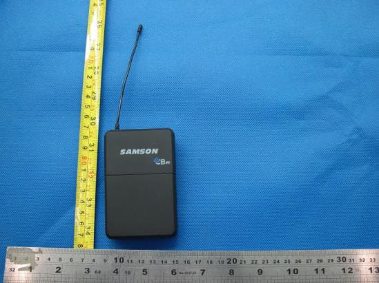
CCRCB99
Dec 30, 2015UHF Wireless System
Equipment Class
TNT - Licensed Non-Broadcast Transmitter Worn on Body