CINUH-1000HANDHELD TRANSMITTER
Chiayo Electronics Co Ltd
Click to zoom
Application Details
- Equipment Class
- TBF - Licensed Broadcast Transmitter Held to Face
- Date of Grant
- Jun 29, 2003
- Application Purpose
- Original Equipment
- Date of Application
- Jun 29, 2003
- Equipment Note
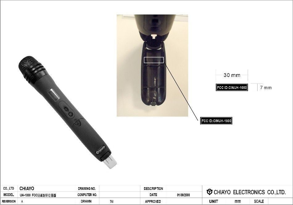
- HANDHELD TRANSMITTER
- Frequency Range
- 614.00000000 - 806.00000000
- Company
- Chiayo Electronics Co Ltd
- Country
- Taiwan
Documents & Files
Document Text
Text extracted from the exhibit documents filed with the FCC. Open a document above to read the original.
Users Manual
LCD Display Multi-channel UHF Wireless Microphone System. INTRODUCTION Congratulation and thank you for the purchase of one of these state-of-the-art PLL Synthesized 1000 channels frequency agile UHF professional wireless systems. As this is a shared operating manual, please read it thoroughly to familiarize with the function of each part before use. Parts and functions Front and Rear Panel Switches & Controls UDR-500 RECEIVER 4If the Volume Control of the receiver is set too high, it may over-drive the input of the mixer, causing distortion. Conversely, if the receiver output is set too low, the overall signal to noise ratio of the system may be reduced. Adjust the output level of the receiver such that highest sound pressure level going into the microphone causes no input overload in the mixer, and yet permits the mixer level controls to operate in their normal range (not too high or too low ). This provides the optimum signal to noise for the entire system. 5Before inserting the batteries, please make sure that they are inserted according to the correct polarity. 6For PLL frequencies agile version, before operation please make sure that the corresponding receiver MUST have the same frequency group and channel number as the transmitter. 7Before making any channel change, please switch off the power supply. The synthesized program works in such a way that a change of channel will only take place after a power off and on action. Otherwise, the previously selected frequency will stay unchanged. 8After making a channel change, please make sure that the corresponding change is made on the matching receiver also. To be exact, changes MUST be made at both the transmitter and receiver. 9Use only brand new Alkaline batteries. Do not use " general purpose " batteries. When batteries are weak, replace the batteries altogether at the same time. Do not mix and use new and old batteries together. 10Position the receiver such that it has the least possible obstructions between it and the transmitter. Line of sight is best! 11The transmitter and the receiver should be as close as possible but not less than 1m. 12A receiver cannot receive signals from two or more transmitters simultaneously. 13Turn the transmitter off when it is not in use. Remove the batteries if it is not to be used for a period of time. UDR-500 is a 1/2 19" casing and specially designed 19" rack mount adapters (optional) is available for rackr installation purposes. Installation instructions are as follow. RF Interference If you encounter receiving interference (from other than an operating TV station), often it can be overcome by adjusting the receiver's squelch control, as described on below. Please note that wireless frequencies are shared with other radio services. According to FCC requlations, wireless microphone operations are unprotected from interference from other licensed operations in the band. If any interference is received by any Government or non-Government operation, the wireless microphone must cease operation. The abovestatement is valid in the U.S.A. Receiver Squelch setting The squelch control setting is per LCD display on the front panel of the receiver is preset at the factory, but can be adjusted if you must use the system in a high RF interference area. If there is audio output from the receiver when your transmitter is OFF, adjust the squelch control so the system will receive the signal from your transmitter but squelch or eliminate the unwanted background RF noise. This adjustment can cause a reduction in usable range of the wireless transmitter, so set the control to the lowest position which reliably mutes the unwanted RF signal. 1If external antenna is used, low loss RF shielded cable should be used and the length of the cable should not exceed 3m. 2Do not place the receive antenna within 1 m of another receiver or antenna. 3The receiver antenna should be kept away from any metal surface. Press Power ON of receiver for 2 seconds and release, the following page will appear. After 5 seconds one of the following pages will automatically appear, depending which one was last selected as main page. Press MENU will roll to next page Press MENU will roll to next page Press MENU will roll to next page Press MENU will roll to next page Press MENU will roll to next page Press MENU will roll to next page Remark : Transmitter is at OFF status. CHIAYO UDR-1000 SQUELCH LEVEL -95 dBm ( 2 ) CF : 01- 01 RF AF USER MODE PRESET MODE USER MODE PRESET MODE To view and roll the various display pages USER NAME RF AF CHIAYO UDR-1000 801.100MHz RF AF CF : 01- 01 RF AF USER NAME RF AF 801.100MHz RF AF If MENU is not pressed again,this page will stay as main page. If MENU is not pressed again,this page will stay as main page. If MENU is not pressed again,this page will stay as main page. If MENU is not pressed again,it will automatically return to one of the 3 main pages. If MENU is not pressed again,it will automatically return to one of the 3 main pages. If MENU is not pressed again,it will automatically return to one of the 3 main pages. Receiver Installation Audio output connection There are two audio outputs on the back of the Diversity receiver. Mic-level balanced and Line-level unbalanced. Use shielded audio cable for the connection between the receiver and the mixer. If the mixer / amp is a 1/4" phone jack, connect a cable from the 1/4" unbalanced audio output from the receiver to the mixer / amp. If the mixer has an XLR input, connect a cable from the balanced XLR audio output from the receiver to the mixer input. Audio output connection as shown below. For best operation, the receiver should be placed at least 1m above the ground and 1m away from a wall or metal surfaces to minimize reflections. The transmitter should also be at least 1m away from a wall or metal surface to minimize reflections. The transmitter should also be at least 1m away from the receiver as shown. Keep antennas away from noise source such as motors…
Text truncated - open the document above for the full version.
Cover Letter(s)
CHIAYO Electronics Co., Ltd. OFFICE : 30, L-27, S-4, Jen-Ai Rd., Taipei, TAIWAN. FACTORY: 88, Chung Hsiao Street 2, Chiayi, TAIWAN TEL: 886-2-2741-5741 TEL: 886-5-271-1000 FAX: 886-2-2752-5242 FAX: 886-5-276-7611 Email: [email protected] Web site: http://www.chiayo.com.t w June 23, 2003 Federal Communications Commissions CONFIDENTIAL ITY LETTER To Whom It May Concern SUB : CINUH-1000 Job # 272UT3 We herewith request FCC not to disclose the following technical data pertaining to CINUH-1000 on FCC website as our competitors might obtain these confidential information from FCC website. 1. Functional Block Diagrams 2. Schematics 3. Parts List 4. Turning Procedures 5. Circuit Descriptions Should you have any queries, please feel free to contact us. Sincerely yours, ----------------------
Test Report
APPLICANT: CHIAYO ELECTRONICS CO., LTD. FCCID: CINUB-1000 REPORT #: C\CHIAYOCIN\274UT3\274UT3TestReport.doc TABLE OF CONTENTS APPLICANT: CHIAYO ELECTRONICS CO., LTD. FCC ID: CINUB-1000 TABLE OF CONTENTS LIST TEST REPORT CONTAINING: PAGE 1........ GENERAL INFORMATION & TECHNICAL DESCRIPTION PAGE 2.........TECHNICAL DESCRIPTION & RF OUTPUT POWER PAGE 3.........MODULATION CHARACTERISTICS & AUDIO FREQUENCY RESPONSE GRAPH MODULATION LIMITING PLOT – 300 Hz PAGE 4.........MODULATION LIMITING PLOT – 2500 Hz MODULATION LIMITING PLOT – 15000 Hz PAGE 5.........OCCUPIED BANDWIDTH AND OCCUPIED BANDWIDTH PLOT PAGE 6.........RADIATED EMISSIONS TEST DATA PAGE 6.........METHOD OF MEASURING RADIATED SPURIOUS EMISSIONS PAGE 7.........FREQUENCY STABILITY TEST DATA PAGE 8-11......EQUIPMENT LIST EXHIBITS CONTAINING: EXHIBIT 1.......FCC ID LABEL SAMPLE & ID LABEL LOCATION EXHIBIT 2.......BLOCK DIAGRAM EXHIBIT 3.......SCHEMATICS EXHIBIT 4.......ALIGNMENT PROCEDURE EXHIBIT 5.......CIRCUIT DESCRIPTION EXHIBIT 6.......USER'S MANUAL EXHIBIT 7.......TEST SET UP PHOTOGRAPH EXHIBIT 8.......EXTERNAL PHOTOGRAPHS EXHIBIT 9.......INTERNAL PHOTOGRAPHS EXHIBIT 10......PARTS LIST APPLICANT: CHIAYO ELECTRONICS CO., LTD. FCCID: CINUB-1000 REPORT #: C\CHIAYOCIN\274UT3\274UT3TestReport.doc Page 1 of 11 GENERAL INFORMATION REQUIRED FOR TYPE ACCEPTANCE 2.1033(c)(1) CHIAYO ELECTRONICS CO., LTD. will manufacture 2.1033(c)(2) the UB-1000 in quantity, for use under FCC RULES PART 74.801, LOW POWER AUXILIARY STATIONS. CHIAYO ELECTRONICS CO., LTD. 30, LANE 27, SEC. 4, JEN AI ROAD TAIPEI, TAIWAN R.O.C., 2.1033 TECHNICAL DESCRIPTION (c)(3) Instruction book. The instruction manual is included as Exhibit 6. (c)(4) Type of Emission: 130K0F3E Bn = 2M + 2DK M = 20000 D = 45kHz(Peak Deviation) K = 1 Bn = 2(20k) + 2(45k)(1) = 130k ALLOWED AUTHORIZED BANDWIDTH = 200kHz. 74.861(e)(5) (c)(5) Frequency Range: Part 74: 614-806 MHz (c)(6) Power Range and Controls: UNIT has no controls. (c)(7) Maximum Output Power Rating: See Next Page. (c)(8) DC Voltages and Current into Final Amplifier: FINAL AMPLIFIER ONLY 9.0V BATTERY Vce = 9.0 Volts Ice = 13.5 mA (c)(9) Tune-up procedure. The tune-up procedure is given in page 4. (c)(10) Complete Circuit Diagrams: The circuit diagram is included as EXHIBIT # 3. The block diagram is included as EXHIBIT #2. APPLICANT: CHIAYO ELECTRONICS CO., LTD. FCCID: CINUB-1000 REPORT #: C\CHIAYOCIN\274UT3\274UT3TestReport.doc Page 2 of 11 2.1033(c)11) Photo or Drawing of Label and sketch of location: See EXHIBIT # 1. 2.1033(c)12) Photos of Equipment: See EXHIBIT #'S 8-9. (c)(13) Description of all circuitry and devices provided for determining and stabilizing frequency. Description of any circuits or devices employed for suppression of spurious radiation, for limit- ing modulation, and for limiting power. This circuitry is described on page 5. Limiting Modulation: The transmitter audio circuitry is contained in IC101, IC102 and IC103. Limiting Power: There is no provision for limiting power. (13) Digital modulation. This unit does not use digital modulation. 2.1033(c)(14) The data required by 2.1046 through 2.1057 is sub- mitted below. 2.1046 RF power output. RF power measured is: OUTPUT POWER: .008 WATTS ERP RF power output procedure is TIA/EIA 603 substitution method. AUDIO LOW PASS FILTER The audio low pass filter is not required in this unit. This unit has no modulation limiter and relies on the fact that the microphones physical properties limits the amplitude. APPLICANT: CHIAYO ELECTRONICS CO., LTD. FCCID: CINUB-1000 REPORT #: C\CHIAYOCIN\274UT3\274UT3TestReport.doc Page 3 of 11 2.1047(a)(b) Modulation characteristics: AUDIO FREQUENCY RESPONSE The audio frequency response was measured in accordance with TIA/EIA Specification 603. The audio frequency response curve is shown below. AUDIO FREQUENCY RESPONSE GRAPH Audio Response -30 -25 -20 -15 -10 -5 0 5 100100010000100000 Frequency mV Data MODULATION LIMITING PLOT – 300 Hz Modulation Limiting 0 10000 20000 30000 40000 50000 60000 -100-80-60-40-200 mV Deviation 300 APPLICANT: CHIAYO ELECTRONICS CO., LTD. FCCID: CINUB-1000 REPORT #: C\CHIAYOCIN\274UT3\274UT3TestReport.doc Page 4 of 11 MODULATION LIMITING PLOT – 2500 Hz Modulation Limiting 0 10000 20000 30000 40000 50000 60000 70000 -100-80-60-40-200 mV Deviation 2500 MODULATION LIMITING PLOT – 15000 Hz Modulation Limiting 0 10000 20000 30000 40000 50000 60000 70000 -100-80-60-40-200 mV Deviation 15000 APPLICANT: CHIAYO ELECTRONICS CO., LTD. FCCID: CINUB-1000 REPORT #: C\CHIAYOCIN\274UT3\274UT3TestReport.doc Page 5 of 11 2.1049(c) Occupied Bandwidth: Data in the plots show that all sidebands between 50 & 100% for the authorized bandwidth are attenuated by at least 25dB. From 100 to 250% of the authorize3d band- width they are attenuated by at least 35dB and beyond 250% 43 log (Po) dB. The plot shows the transmitter modulated with 15000 Hz(the highest modulation frequen- cy), adjusted for 50% modulation plus 16 dB. The spectrum analyzer was set with the unmodulated carrier at the top of the screen. The test procedure diagram and occupied bandwidth plots follow. Wireless Microphone transmitter: Test procedure diagram Transmitter Coupler 50 ohm under test Resistive Load Audio Spectrum Oscillator Analyzer REQUIREMENT: PART 74: 200kHz EMISSION BANDWIDTH. OCCUPIED BANDWIDTH PLOT APPLICANT: CHIAYO ELECTRONICS CO., LTD. FCCID: CINUB-1000 REPORT #: C\CHIAYOCIN\274UT3\274UT3TestReport.doc Page 6 of 11 2.1051 Spurious emissions at antenna terminals (conducted): Not Applicable no antenna connector. 2.1053(a)(b) Field strength of spurious emissions: NAME OF TEST: RADIATED SPURIOUS EMISSIONS REQUIREMENTS: Emissions must be 43 +10log(Po) dB below the mean power output of the transmitter. 43 + 10 log(0.008) = 22.03 dB TEST DATA: Emission Frequency MHz dB Below Carrier dBm 740.00 0 9 1,480.00 42 -33 2,220.00 33 -24 2,960.00 57 -48 3,700.00 57 -48 4,440.00 55 -46 750.00 0 9 1,500.00 43 -34 2,250.00 31 -22 3,000.00 59 -50 763.00 0 9 1,526.00 48 -…
Text truncated - open the document above for the full version.
Contact Information
Applicant
Teresa Hung(Senior Manager)
Test Firm
Timco Engineering, Inc.S Sanders
Technical Specifications
| # | Rule Parts | Frequency Range | Power Output | Emission | Tolerance |
|---|---|---|---|---|---|
| 1 | 74.861 | 614 MHz - 806 MHz | 4.00 mW | 130KF3E | 50.0000000000 ppm |
Other Applications from Chiayo Electronics Co Ltd

CINDH-5400
Jan 13, 20222.4G Digital Wireless Handheld Microphone
Equipment Class
DTS - Digital Transmission SystemCINSQ-6100IRDA
Jun 11, 2015Wireless Mircophone
Equipment Class
TBF - Licensed Broadcast Transmitter Held to Face
CINSM-6100IRDA
Jun 04, 2015Wireless Beltpack Transmitter
Equipment Class
TBT - Licensed Broadcast Transmitter Worn on Body
CINSM-716-470
Jun 02, 2015Wireless Microphone Transmitter
Equipment Class
TBT - Licensed Broadcast Transmitter Worn on Body
CINMT-U8-470
May 31, 2015MINI TRANSMITTER
Equipment Class
TBT - Licensed Broadcast Transmitter Worn on Body