CLHCP750900 MHz 40 Channel Analog Cordless Telephone
S Megga Telecommunications Ltd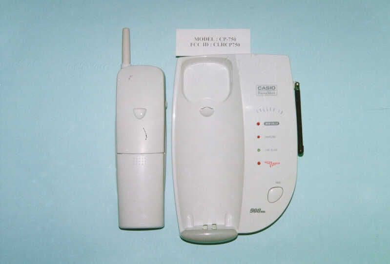
Click to zoom
Application Details
- Equipment Class
- DXT - Part 15 Low Power Transceiver, Rx Verified
- Date of Grant
- May 23, 1999
- Application Purpose
- Original Equipment
- Date of Application
- Apr 13, 1999
- Equipment Note
- 900 MHz 40 Channel Analog Cordless Telephone
- Frequency Range
- 925.08000000 - 927.42000000
- Country
- Hong Kong
Documents & Files
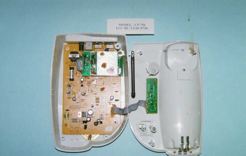
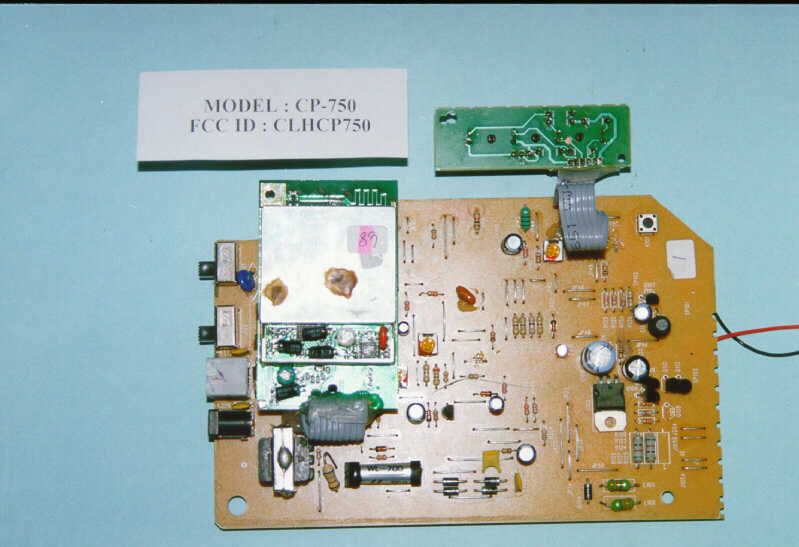
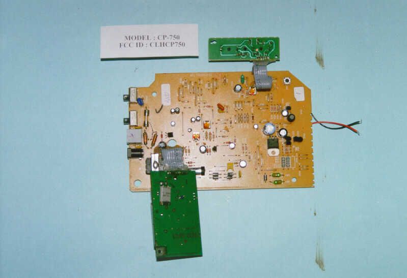
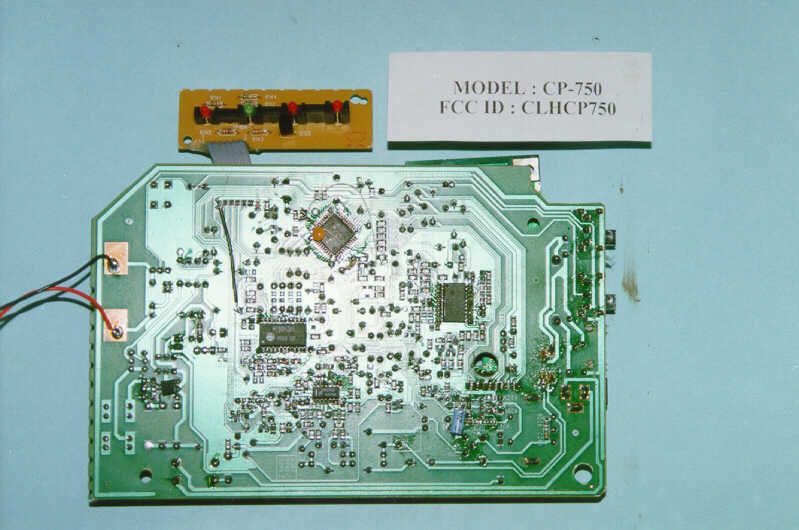
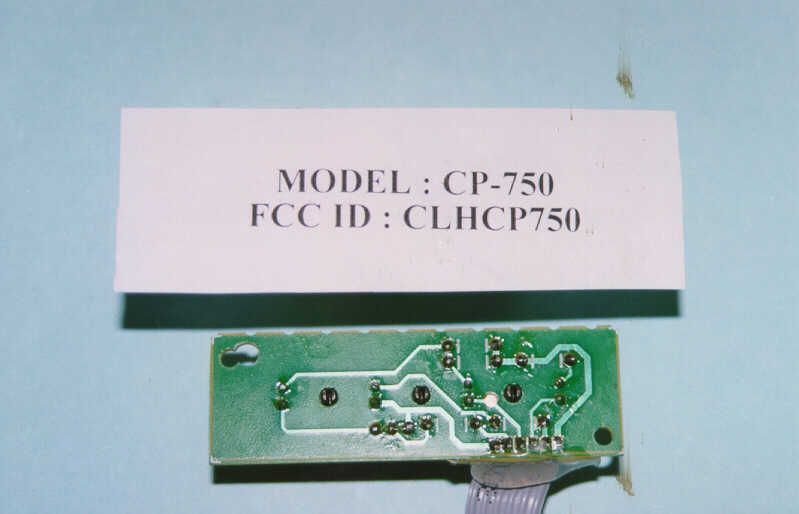
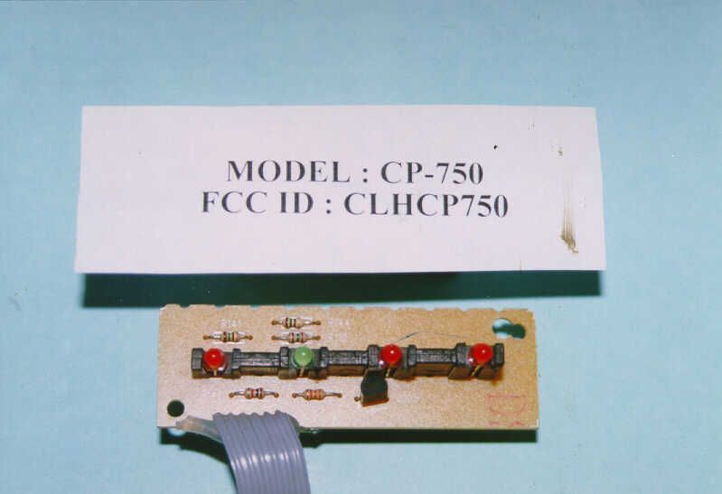
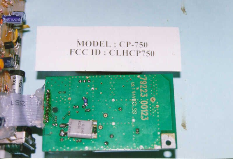
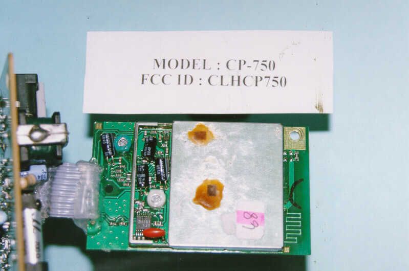
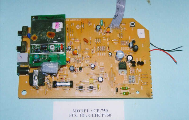
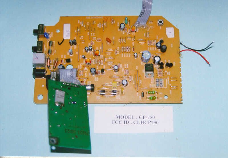
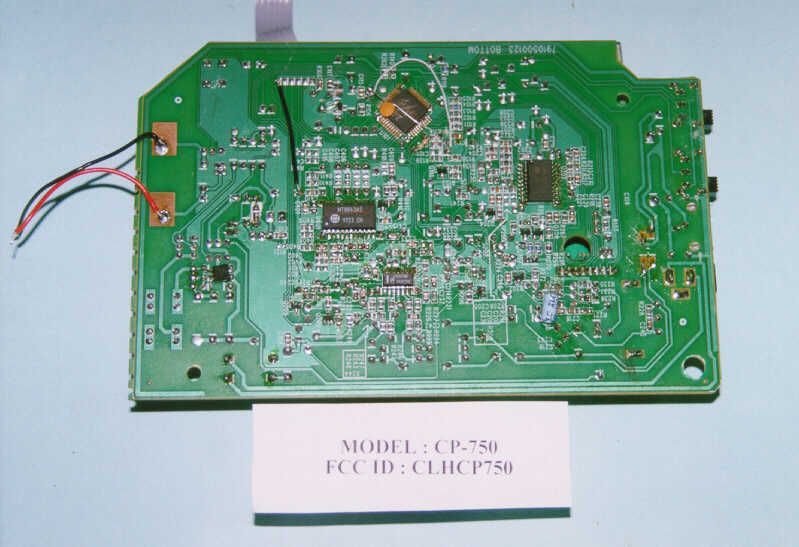
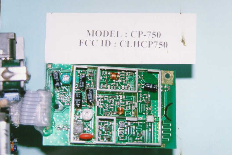
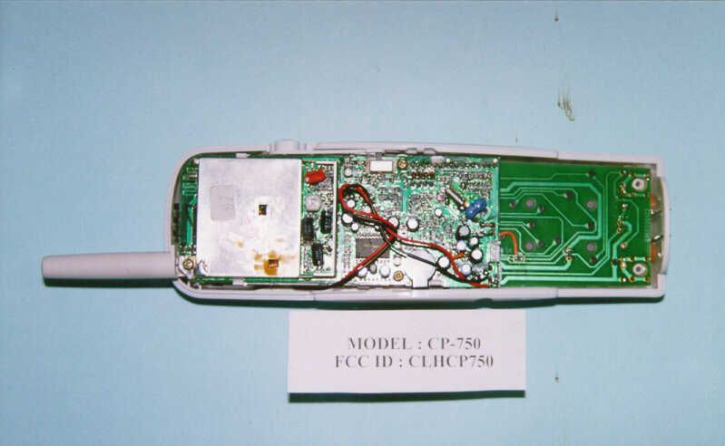
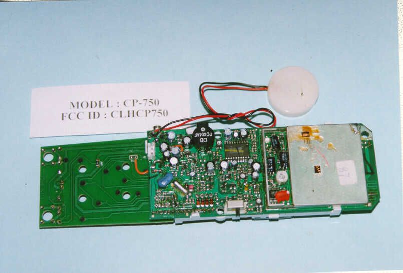
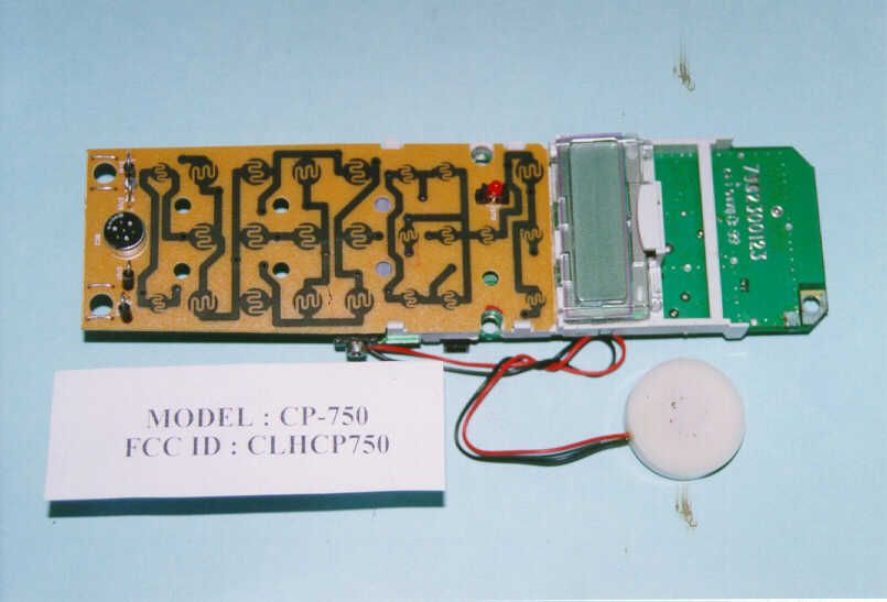
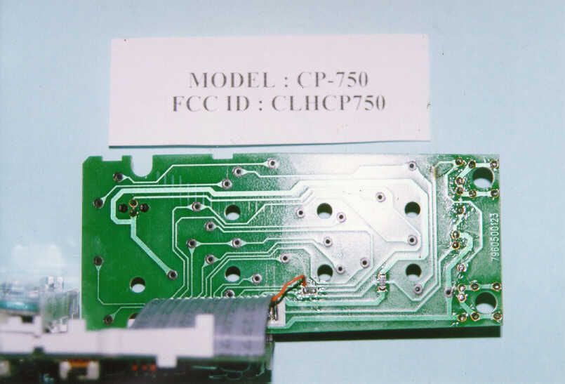
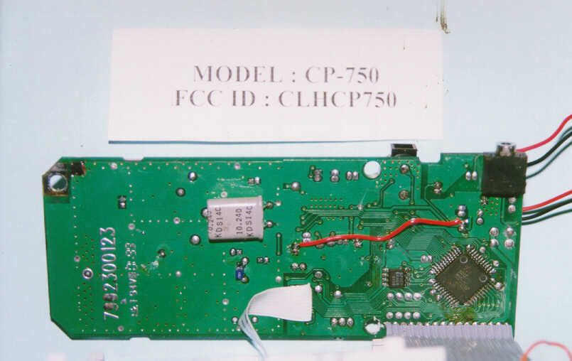
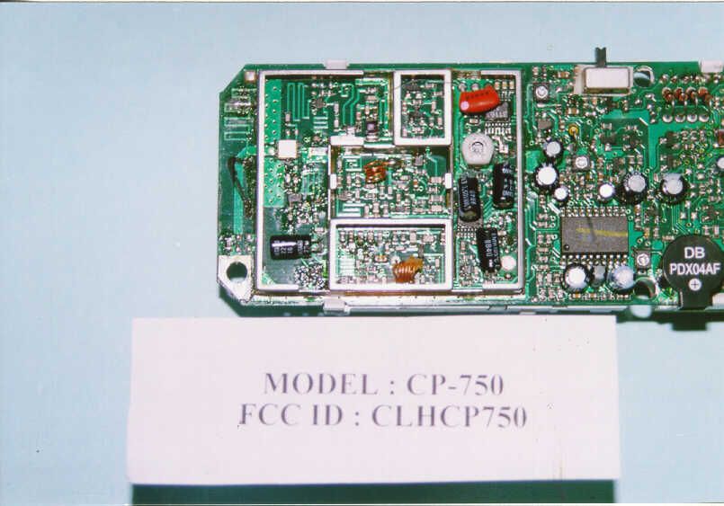
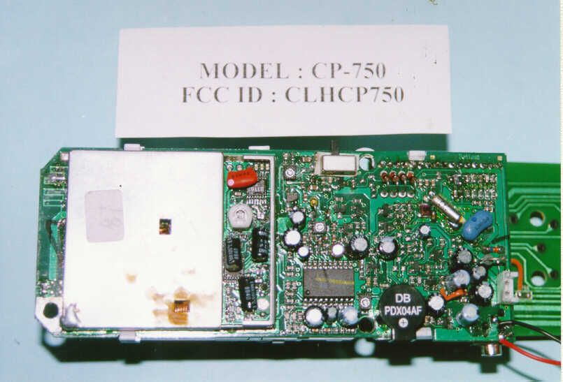
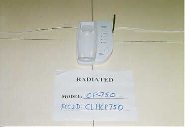
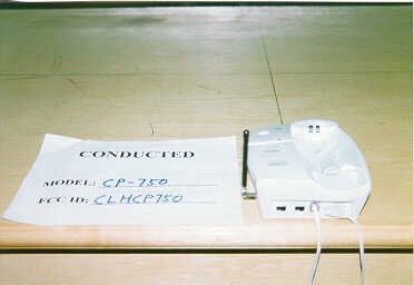
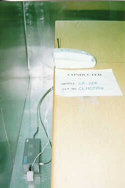
Document Text
Text extracted from the exhibit documents filed with the FCC. Open a document above to read the original.
Users Manual
1 2 3 1 2 1 1 1 B A wall mount bracket is included and can be installed if needed. Tightly coil the telephone cord around the four guides on the inside of the wall mounting bracket. Pull the telephone cord through the center opening on the wall mounting bracket. Refer to the drawing. The handset can be charged face out or face down, even when wall mounted. INITIAL SETUP WALL/DESK USE This switch tells the CP-750 to dial out with either touchtone or pulse signals to match the service you have with your local telephone company. The CP-750 is shipped with the TONE/PULSE SWITCH in the TONE position. If you do not have touchtone service, set the switch to pulse on the back of the charging cradle. TONE = for Touchtone systems PULSE = for Rotary dialing or Pulse systems TONE/PULSE SWITCH PULSE TONE The CP-750 is shipped with the base and handset RINGER ON/OFF SWITCHES in the ON position. You can independently set the ringers of the CP-750 to ON or OFF. RINGER ON/OFF C NOTE: nIf the handset is in “Standby Mode” but not in the charging cradle, the display will go blank after a short time to conserve battery power. HANDSET / TELEPHONE OPERATION STANDBY MODE The CP-750 is in “Standby” mode whenever it is idle, waiting for a call. If the handset is in the charging cradle, the display will either be blank OR If you have new caller ID entries from recent unanswered calls, it will show the “NEW CALLERS” message with the number of new callers at the lower far right of the display screen. Press CALLER ID to view the names and numbers of “New Callers”. 1 2 Pick up the handset and press TALK. The following display will be briefly shown. This display indicates that the handset is estab- lishing contact with the charging cradle. TO PLACE A CALL A dial tone will be established. (In this example, CH03 is the current channel number of 40 available channels in your area.) Wait for dial tone and dial the phone number. The number will appear in the display as you dial. NOTE: nThe LINE IN-USE INDICATOR on the charging cradle lights solid to show the handset is in use. 1 To hang up, press TALK or return the handset to the charging cradle. TO END A CALL NOTE: nWhen you return the handset to the charging cradle, you are hanging up the phone and returning to Standby Mode. The CP-750 is now ready to receive a call and the CHARGING INDICATOR lights solid to show that the battery is charging. 1 Press TALK twice (“off” and “on.”) Wait for dial tone and dial the correct number. IF YOU MISDIALED A NUMBER 1 2 1 2 TO RECEIVE A CALL When the phone rings, pick up the cordless handset and press TALK. You will briefly see the “SCANNING CHANNELS” display, followed by the “VOLUME” display. Speak to the caller. To hang up, press TALK on the handset or return the handset to the charging cradle. HANDSET VOLUME CONTROL Whenever the CP-750 is in “Talk” mode, the handset volume will be displayed. Press the DOWN or UP ARROW KEY to adjust the volume. When TALK is pressed, the handset volume returns to the volume level at which you programmed it (see PROGRAMMING THE CP-750, “Default Volume”). When the CP-750 detects a modem in use on the line to which it is connected, the Modem Monitor TM feature prevents the CP-750 from going off-hook. When you attempt to make a call on the CP-750 and a modem is connected, you will hear the modem data through the handset. The data you hear is protected from interruption. The MODEM MONITOR TM INDICATOR on the base will flash slowly and when you attempt to go off- hook the handset will display: MODEM MONITOR TM NOTE: nIf you wish to override Modem Monitor TM after pressing TALK you can do so by pressing 9. (You may also need to manually deactivate the modem activity at your computer or fax machine.) About 10 seconds after you enter “Talk” mode, a Call Timer will appear on the display. The timer will automatically be reset whenever you place a new call. NOTES: nThe length of time shown on the display is intended only to be an estimate duration of a phone call. CASIO PHONEMATE makes no guarantees regarding the accuracy of this timer. nThe Call Timer will not be disrupted if HOLD is pressed. The Hold timer (5 minute count down timer) will display and the Call Timer will continue, hidden from view, during any Hold mode. CALL TIMER 1 Press the RIGHT ARROW (CHANNEL) KEY to view the approximate length of the last call after you have hung up the phone. LAST CALL TIME DISPLAY After TALK is pressed, the CP-750 selects the best of 40 available channels in your area. If you hear noise or interference while using the CP-750, press CHANNEL on the handset to change channels. CHANGING CHANNELS MANUALLY 1 If you subscribe to a call waiting service and you receive another call while using the phone, press FLASH to answer the second call. To return to the first call, press FLASH again. FLASH/CALL WAITING FLASH may also be used on a business phone system (CENTREX, PBX) for transferring calls. 1 2 Press HOLD to place a call on hold. The TALK INDICATOR will flash slowly. You may place a call on hold while using the cordless handset. HOLD NOTE: nYou can place a call on hold for up to 5 minutes. During HOLD, do not return the handset to the charging cradle. Doing so will disconnect the caller. To continue your phone conversation, press TALK, HOLD, or pick up an extension phone connected to the same line. When the extension phone is picked up, the CP-750 automatically disconnects itself from the line. Extension phone pick- up during HS Hold mode will discontinue the Hold mode, connect the call to the new extension phone, and cause the CP-750 to go idle after a 10 -second display time out. NOTE: nThe Call Timer will not be disrupted if HOLD is pressed. The Hold timer (5 minute count down timer) will display and the Call Timer will continue, hidden from view, during any Hold mode. 1 2 Send-Key Dialing is extremely reliable because you can see the number you have entered before actually dialing it. DIALING A NUMBER USING THE SEND KEY (D…
Text truncated - open the document above for the full version.
Test Report
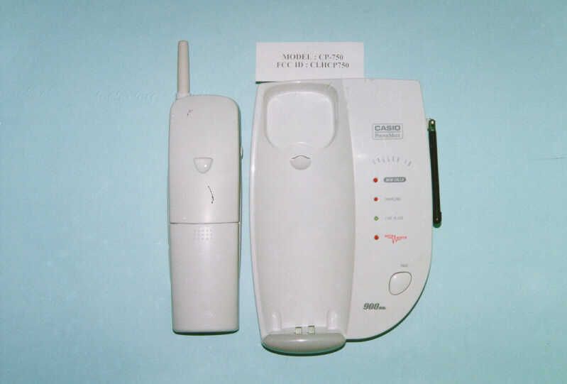
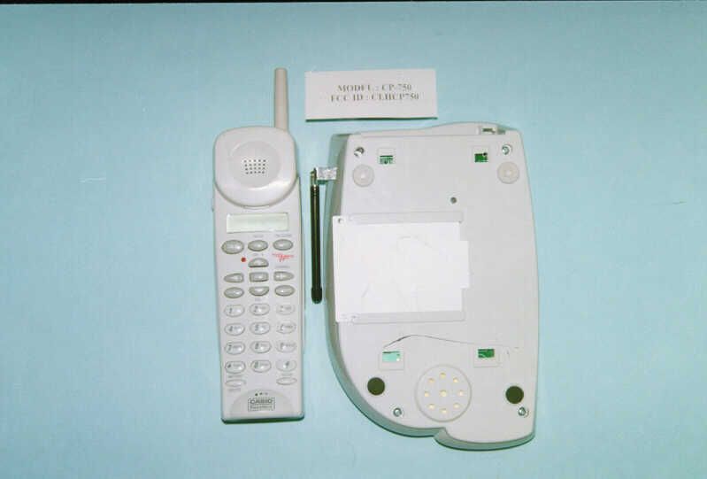
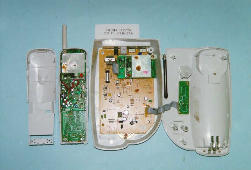
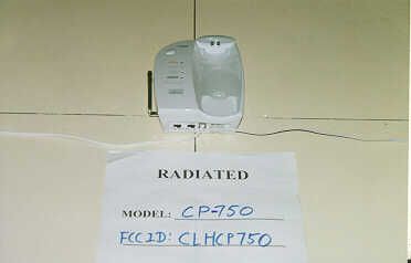
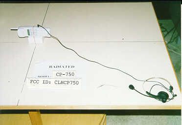
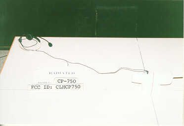
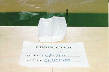
• The test results reported in this report shall refer only to the sample actually tested and shall not refer or be deemed to refer to bulk from which such a sample may be said to have been obtained. • This report shall not be reproduced except in full without prior authorization form Intertek Testing Services Limited FCC ID: CLHCP750 S. Megga Telecommunications Ltd. Application For Certification 900MHz 40 Channel Analog Modulation Cordless Telephone with Caller ID (FCC ID: CLHCP750) WO# 99011741 AL/at April 14, 1999 INTERTEK TESTING SERVICES FCC ID: CLHCP750 i LIST OF EXHIBITS INTRODUCTION EXHIBIT 1:General Description EXHIBIT 2:System Test Configuration EXHIBIT 3:Emission Results EXHIBIT 4:Equipment Photographs EXHIBIT 5:Product Labelling EXHIBIT 6:Technical Specifications EXHIBIT 7:Instruction Manual EXHIBIT 8:Security Code Information INTERTEK TESTING SERVICES FCC ID: CLHCP750 ii MEASUREMENT/TECHNICAL REPORT S. Megga Telecommunications Ltd - MODEL: CP-750 CP-749 FCC ID: CLHCP750 This report concerns (check one:)Original Grant X Class II Change_____ Equipment Type: Low Power Transmitter (example: computer, modem, transmitter, etc.) Deferred grant requested per 47 CFR 0.457(d)(1)(ii)?Yes No X If yes, defer until : date Company Name agrees to notify the Commission by: date of the intended date of announcement of the product so that the grant can be issued on that date. Transition Rules Request per 15.37?Yes No X If no, assumed Part 15, Subpart C for intentional radiator - the new 47 CFR [10-1-96 Edition] provision. Report prepared by:Alfred Lo Intertek Testing Services. 2/F., Garment Centre, 576 Castle Peak Road, Kowloon, Hong Kong. Phone:852-2746-8217 Fax:852-2785-5487 INTERTEK TESTING SERVICES FCC ID: CLHCP750 iii Table of Contents 1.0 General Description ................................................................................................................. 2 1.1 Product Description ................................................................................................................ 2 1.2 Related Submittal(s) Grants .................................................................................................... 3 1.3 Test Methodology ................................................................................................................... 3 1.4 Test Facility ............................................................................................................................ 3 2.0 System Test Configuration ...................................................................................................... 5 2.1 Justification............................................................................................................................. 5 2.2 EUT Exercising Software ....................................................................................................... 5 2.3 Support Equipment List and Description ................................................................................ 6 2.4 Equipment Modification ......................................................................................................... 7 3.0 Emission Results ....................................................................................................................... 9 3.1 Field Strength Calculation..................................................................................................... 10 3.2 Radiated Emission Configuration Photograph - Base Unit.................................................... 11 3.3 Radiated Emission Data - Base Unit..........................................................................................12 3.4 Radiated Emission Configuration Photograph - Handset .........................................................17 3.5 Radiated Emission Configuration Data - Handset ................................................................. 18 3.6 Radiated Emission on the bandedge...................................................................................... 21 3.7 Line Conducted Configuration Photograph - Base Unit ....................................................... 23 3.8 Line Conducted Data - Base Unit ..............................................................................................24 4.0 Equipment Photographs ........................................................................................................ 26 5.0 Product Labelling ................................................................................................................... 28 6.0 Technical Specifications ......................................................................................................... 30 7.0 Instruction Manual ......................................................................................................................32 8.0 Security Code Information .........................................................................................................34 INTERTEK TESTING SERVICES FCC ID: CLHCP750 iv List of attached file Exhibit typeFile Descriptionfilename Cover LetterLetter of Agencyletter.pdf Test ReportTest Reportreport.doc Operation DescriptionTechnical Descriptiondescri.pdf Test Setup PhotoRadiated Emission for Basebase1.jpg, base2.jpg Test Setup PhotoRadiated Emission for Handsethandset1.jpg, handset2.jpg Test ReportEmission Plotemission.pdf Test Setup PhotoConducted Emissionconduct1.jpg to conduct3.jpg Test ReportConducted Emission Test Resultconduct.pdf External PhotoExternal Photoophoto1.jpg, ophoto2.jpg Internal PhotoInternal Photoiphoto1.jpg to iphoto19.jpg Block DiagramBlock Diagramblock.pdf SchematicsCircuit Diagramcircuit.pdf ID Label/LocationLabel Artwork and Locationlabel.pdf User ManualUser Manualmanual.pdf INTERTEK TESTING SERVICES FCC ID: CLHCP750 1 EXHIBIT 1 GENERAL DESCRIPTION INTERTEK TESTING SERVICES FCC ID: CLHCP750 2 1.0 General Description 1.1Product Description The CP-750 and CP-749 are 900MHz 40 Channel Analog Modulation with Caller ID. T…
Text truncated - open the document above for the full version.
Contact Information
Applicant
C. W. Cheung(Senior Manager)
852 2614-1111Fax: 852 2614-6649
Technical Contact
Intertek Testing Services Hong Kong LtdAlfred Lo
[email protected](852) 2746-8217
2/F., Garment Center, · Kowloon · Hong Kong
Non-Technical Contact
Intertek Testing Services Hong Kong LtdAlfred Lo
[email protected](852) 2746-8217
Test Firm
Intertek Testing Services Hong KongBilly Chow
Technical Specifications
| # | Rule Parts | Frequency Range | Power Output |
|---|---|---|---|
| 2 | - | 925.08 MHz - 927.42 MHz | - |
Other Applications from S Megga Telecommunications Ltd
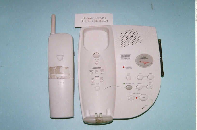
CLHTC920
May 23, 1999900 MHz 40 Channel Analog Cordless Telephone
Equipment Class
DXT - Part 15 Low Power Transceiver, Rx Verified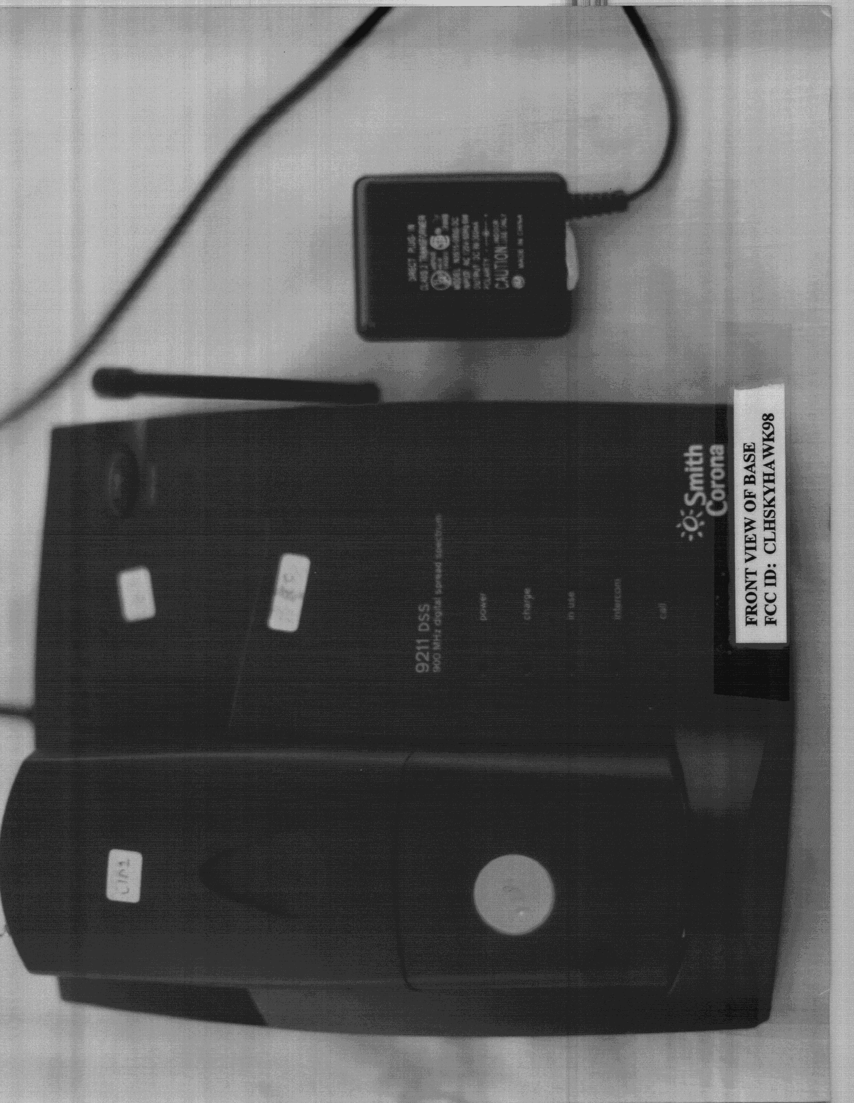
CLHSKYHAWK98
Sep 07, 1998Cordless Telephone
Equipment Class
DXT - Part 15 Low Power Transceiver, Rx VerifiedCLHHUG091
Dec 17, 1997Cordless Telephone System Max. Output Power 26 Milliwatts
Equipment Class
DSS - Part 15 Spread Spectrum TransmitterCLH2570
Jul 28, 1997ETS - Part 15 Cordless Telephone System
Equipment Class
ETS - Part 15 Cordless Telephone SystemCLH2560
May 27, 1997ETS - Part 15 Cordless Telephone System
Equipment Class
ETS - Part 15 Cordless Telephone System