CWTK3201Photo Printer with Bluetooth
ALPS ALPINE CO., LTD.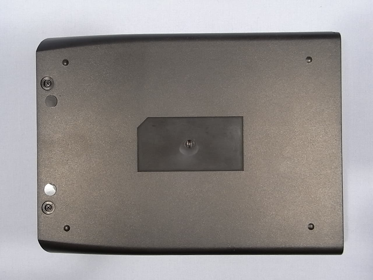
Click to zoom
Application Details
- Equipment Class
- DSS - Part 15 Spread Spectrum Transmitter
- Date of Grant
- Sep 16, 2010
- Application Purpose
- Original Equipment
- Date of Application
- Sep 16, 2010
- Equipment Note
- Photo Printer with Bluetooth
- Frequency Range
- 2402.00000000 - 2480.00000000
- Company
- ALPS ALPINE CO., LTD.
- Country
- Japan
Documents & Files
Document Text
Text extracted from the exhibit documents filed with the FCC. Open a document above to read the original.
Users Manual
PROBLEMSOLUTION The photo has streaksDO NOT: • Send another image to be printed. DO: • Turn off the printer. Open the paper tray door and remove the photo paper. Place one sheet of photo paper upside down (with the watermark facing up) in the paper tray. Gently glide the photo paper under the print head. Close the paper tray door. The sheet of photo paper will automatically eject. Open the paper tray door and reload the photo paper. The paper jammed before printing (nothing has been ejected) DO NOT: • Send another image to be printed. DO: • Open paper tray door. • Check to see if there is paper in the tray. • If so, ensure the paper is loaded correctly. • If not, add a new pack of Polaroid ZINK Photo Paper. The paper jammed while printing (part of the image has already ejected) DO NOT: • Pull out paper. DO: • Turn off the printer. Open the paper tray door and remove media. Place one sheet of photo paper upside down (with the watermark facing up) in the paper tray. Gently glide the photo paper under the print head. Close the paper tray door. The sheet of photo paper will automatically eject. Open the paper tray door and reload the photo paper. Close the paper tray door. If all else fails...DO: • Turn off the printer. If the printer will not power off, remove the battery cover and the battery. Replace the battery and batter cover. Turn on the printer. For additional troubleshooting and frequently asked questions, visit www.polaroid.com. Troubleshooting 1. Select the image you would like to print from the stored images on your camera cell phone. In the “options” menu, select “send via Bluetooth.” Search for devices and select the Polaroid printer and print. 2. If you are unable to print from “send via Bluetooth,” select “connectivity” or “Bluetooth” under the “settings” or “tools” menu. Search for devices and select the Polaroid printer. Once paired, go back to stored images and select the image you want to print. In the “options” menu, select “beam” or “send via Bluetooth”. Select the Polaroid printer and print. 3. If your camera cell phone does not include “send via Bluetooth” under the “options” menu, select the image you want to print. Select the “options” menu and select “print via Bluetooth”. Search for devices, select the Polaroid printer, and print. Printing: Camera Cell Phone Printing: Digital Camera 1. Connect your digital camera and printer to determine if a print option or printer icon is automatically displayed on the camera screen. 2. If no print option appears, select “menu” and navigate to confirm that PictBridge is enabled. Note: if “USB” is displayed under “settings” then PictBridge is NOT enabled. 3. Once PictBridge is enabled, select the image you want to print and follow the on-screen instructions to print. Notes: • Do not disconnect the USB cord until entire printing process is complete. • Do not turn off the printer while printing. • Do not open paper tray door while printing. • To print the date on your photo, ensure the Date Stamp feature on your digital camera is enabled. Product Diagram Installing and Charging the Battery To install the battery: 1 Remove battery door cover. 2 Install battery. 3 Replace battery door cover. To charge the battery: 1. Install the battery (see above steps). 2. Connect the AC adapter to the printer and the power source. Notes: • Before using the printer on battery power, fully charge the battery for 2.5 hours. • You can print photos while plugged into the power source. Installing ZINK Paper® 1 Press and release latch on the paper tray door. 2 Unwrap the 10-pack of ZINK Paper. 3 Slide the 10-pack of ZINK Paper into the printer. Make sure the ZINK Smart Sheet™ is placed facedown. Close the printer tray door. The ZINK Smart Sheet will automatically eject. 4 Press and hold the POWER button to turn on the printer. Notes: • The printer must be empty before refilling. Do not fill the printer with more than one 10-pack of ZINK Paper. Having more than 10 sheets of paper may damage the printer. • Aviod bending the ZINK Paper. • Only hold the ZINK Paper by its edges; avoid touching the printing surface with your fingers. To install the Paper: Press and hold the Power Button ZI NK ® Smar tshe e t ® ! Safety Information Hereby, Summit Global Group declares that this Instant Mobile Printer is in compliance with the essential requirements and other relevant provisions of Directive 1999/5/EC. Changes or modifications not expressly approved by the party responsible for compliance could void the user’s authority to operate the equipment. NOTICE This equipment has been tested and found to comply with the limits for a Class B digital device, pursuant to part 15 of the FCC Rules. These limits are designed to provide reasonable protection against harmful interference in a residential installation. This equipment generates, uses, and can radiate radio frequency energy and, if not installed and used in accordance with the instructions, may cause harmful interference to radio communications. However, there is no guarantee that interference will not occur in a particular installation. If this equipment does not cause harmful interference to radio or television reception, which can be determined by turning the equipment off and on, the user is encouraged to try to correct the interference by one or more of the following measures: - Reorient or relocate the receiving antenna - Increase the separation between the equipment and receiver - Connect the equipment into an outlet or on a circuit different from that to which the receiver is connected - Consult the dealer or an experienced radio/TV technician for help. This transmitter must not be co-located or operated in conjunction with any other antenna or transmitter. This equipment complies with the FCC/IC radiation exposure limits sent forth for uncontrolled equipment and meets the FCC radio frequency (RF) Exposure Guidelines in Supplement C to OET62 and RSS-102 for the IC radio frequency (RF) Exposure rules. This e…
Text truncated - open the document above for the full version.
Cover Letter(s)
1 Mika Kaneko 差出人: Zacta Tatsu Sato [[email protected]] 送信日時: 2010年9月17日金曜日 14:33 宛先: Mika Kaneko 件名: Re: Alps Electric Co., Ltd., FCC ID: CWTK3201, Assessment NO.: AN10T0865, Notice#1 添付ファイル: Revised 2_Block Diagram.pdf Revised 2_Block Diagram.pdf (3... Hello Ms. Kaneko, Please see my answer below. Best Regards, Tatsu Sato ◇◇◇◇◇◇◇◇◇◇◇◇◇◇◇◇◇◇◇◇◇◇◇◇◇◇ ZACTA Technology Corporation Technical Division Tatsuhiko SATO 4149-7, 5-Chome, Hachimanpara, Yonezawa, Yamagata, 992-1128 Japan Phone: +81-238-28-2881 FAX: +81-238-28-2888 URL: http://www.zacta.co.jp e-mail: [email protected] ◇◇◇◇◇◇◇◇◇◇◇◇◇◇◇◇◇◇◇◇◇◇◇◇◇◇ Privileged or confidential information may be contained in this mail. If you are not the named addressee, you may not copy or deliver this message or its attachments to anyone. Please permanently delete this message and its attachments and kindly notify the sender by reply email. Zacta Technology Corp. do not accept liability for any errors or other defect that arise as a result of e-mail transmission. Thank you. (2010/09/15 16:04), [email protected] wrote: > Hello Mr. Sato, > > Review of this application is complete. Please reply to the following issues. > > QUESTION #1: > EUT size (160 x 130 mm) is bigger than the palm of hand, please add 15.19 statement on the label. [ZACTA] Instead of 15.19 statement, FCC logo is displayed in the label of the device because it belongs to FCC 15B DoC. Reference: Attached FCC 15B Doc report *Not exhibits > QUESTION #2: > Per Block Diagram, External antenna is used, however, Printed Antenna / Chip Antenna is stated as Antenna in the report. Please revise the wrong one. [ZACTA] Block Diagram was revised. Please find attached Revised Block Diagram. And the "Chip antenna" that had been described to the test report was corrected to "Printed antenna". Please find attached Revised Test Report. 2 Reference: Attached Antenna Information *Not exhibits > QUESTION #3: >> From Operational description, EUT is powered by either AC Adapter or Battery, however, from Test Setup photos, only AC Adapter operation mode was tested for Radiated emission. Please measure Battery operation mode in three orthogonal planes. [ZACTA] We measured in Battery operation mode (three-axis) and revised the test report. Please find attached Revised Test Report and Revised Test Setup Photos. > QUESTION #4: > Since External Photos are requesting for short term confidentiality, please revise the label location drawings. [ZACTA] Since we have revised the label location drawings, please find attached Revised Label information. We appreciate your help to this matter. > Best Regards, > > > Mika Kaneko > Technical Reviewer > UL CCS > > The items indicated above must be submitted before processing can > continue on the above referenced application. Failure to provide the > requested information within 30 days of the original e-mail date may > result in application dismissal and forfeiture of the filing fee. > Also, please note that partial responses increase processing time and > should not be submitted. Any questions about the content of this > correspondence should be directed to the e-mail address listed below > the name of the sender. Revised documentation should not be emailed, > but instead should be submitted through "Add Attachment・function at > the UL-CCS website. Please have your Assessment Number and FCC ID/IC > Certification number handy. You may use the following link: > https://cert.ccsemc.com/filing/ > > > __________ Information from ESET NOD32 Antivirus, version of virus > signature database 5451 (20100914) __________ > > The message was checked by ESET NOD32 Antivirus. > > http://www.eset.com > > > >
External Photos
Alps Electric Co., Ltd. FCC ID: CWTK3201 IC: 1788F-TK3201 Page 1 of 3 Alps Electric Co., Ltd. FCC ID: CWTK3201 IC: 1788F-TK3201 Page 2 of 3 Alps Electric Co., Ltd. FCC ID: CWTK3201 IC: 1788F-TK3201 Page 3 of 3
ID Label/Location Info
Model No. P340 16V INPUT 2.5A S/N : Model No. P340 16V INPUT 2.5A S/N : MP Start (US/EU) Cut in (Add JPN/AUS) MADE IN CHINA / FABRIQUE EN CHINE MADE IN CHINA / FABRIQUE EN CHINE 1788F-TK3201 1788F-TK3201 CWTK3201 CWTK3201 Label Position Label PositionLabel Position Label Position ○ Bottom View ○ Bottom View○ Bottom View ○ Bottom View ○ Top View ○ Top View○ Top View ○ Top View Rating Label Position Product Brand Name
Internal Photos
Alps Electric Co., Ltd. FCC ID: CWTK3201 IC: 1788F-TK3201 Page 1 of 6 Alps Electric Co., Ltd. FCC ID: CWTK3201 IC: 1788F-TK3201 Page 2 of 6 Alps Electric Co., Ltd. FCC ID: CWTK3201 IC: 1788F-TK3201 Page 3 of 6 Alps Electric Co., Ltd. FCC ID: CWTK3201 IC: 1788F-TK3201 Page 4 of 6 Alps Electric Co., Ltd. FCC ID: CWTK3201 IC: 1788F-TK3201 Page 5 of 6 Alps Electric Co., Ltd. FCC ID: CWTK3201 IC: 1788F-TK3201 Page 6 of 6
RF Exposure Info
ZACTA Technology Corporation RF exposure statement To whom it may concern: ZACTA Technology Corporation Address: 4149-7 Hachimanpara 5-chome Yonezawa-shi, Yamagata 992-1128 Japan is authorized as an agency from Applicant: Alps Electric Co., Ltd. to act on their behalf in all matters relating to applications for equipment authorization, including testing the device and the signing of all documents relating to these matters. The maximum peak output power of the product FCC ID: CWTK3201 is 0.39 mW. RF exposure calculation PG S = 4*π*R 2 0.39*0.776 0.30264 mW S = 4*π*R 2 = 4*π*(20cm) 2 = 0.0000602 mW/cm 2 (limit=1.0mW/cm 2 ) where: S = power density P = power input to the antenna (0.39 mW) G = power gain of the antenna in the direction of interest relative to an isotropic radiator (0.776 mW = -1.1dBi) R = distance to the center of radiation of the antenna (20 cm) Therefore, the product FCC ID: CWTK3201 is deemed to comply with the requirements of FCC 47CFR 2.1093 ‘Radiofrequency radiation exposure evaluation: portable devices’.
Test Report
Report number: Z071C-10146 Page 2 of 63 ZACTA Technology Corp. FCC ID: CWTK3201 FCC 15C Rev.3.0 IC Certification Number: 1788F-TK3201 Table of contents Page 1. Summary of Test .................................................................................................................................................................. 5 1.1 Purpose of test .......................................................................................................................................................................... 5 1.2 Standards .................................................................................................................................................................................. 5 1.3 Summary of test results ........................................................................................................................................................... 5 1.4 Deviation from the standard .................................................................................................................................................... 5 1.5 Modification to the EUT by laboratory .................................................................................................................................. 5 2. Equipment description ......................................................................................................................................................... 6 2.1 General Description of equipment .......................................................................................................................................... 6 2.2 EUT information ...................................................................................................................................................................... 6 2.3 Operating channels and frequencies ....................................................................................................................................... 7 2.4 Operating mode ....................................................................................................................................................................... 8 3. Configuration information................................................................................................................................................... 9 3.1 EUT and Peripheral(s) used .................................................................................................................................................... 9 3.2 Cable(s) information ................................................................................................................................................................ 9 3.3 System configuration ............................................................................................................................................................ 10 4. Test Type and Results ........................................................................................................................................................ 11 4.1 20dB Bandwidth / Occupied Bandwidth .............................................................................................................................. 11 4.1.1 Test Procedure [ FCC 15.247(a)(1), IC RSS-210 A8.1(a) ] ......................................................................................... 11 4.1.2 Measurement Setup ......................................................................................................................................................... 11 4.1.3 Limit of Bandwidth at 20 dB below ................................................................................................................................ 11 4.1.4 Measurement Result ........................................................................................................................................................ 11 4.1.5 Trace Data ........................................................................................................................................................................ 11 4.2 Carrier Frequency Separation .............................................................................................................................................. 13 4.2.1 Test Procedure [ FCC 15.247(a)(1), IC RSS-210 A8.1(b) ] ........................................................................................ 13 4.2.2 Measurement Setup ......................................................................................................................................................... 13 4.2.3 Limit of Carrier Frequency Separation ........................................................................................................................... 13 4.2.4 Measurement Result ........................................................................................................................................................ 13 4.2.5 Trace Data ........................................................................................................................................................................ 13 4.3 Number of Hopping Frequencies ........................................................................................................................................ 15 4.3.1 Test Procedure [ FCC 15.247(a)(1)(iii), IC RSS-210 A8.1(d) ] .................................................................................. 15 4.3.2 Measurement Setup ......................................................................................................................................................... 15 4.3.3 Limit of Number of Hopping Frequencies ..................................................................................................................... 15 4.3.4 Measurement Result .................................................................................................…
Text truncated - open the document above for the full version.
Test Setup Photos
Alps Electric Co., Ltd. FCC ID: CWTK3201 IC: 1788F-TK3201 Page 1 of 2 System configuration (RF Conducted test) Transmitter Radiated Spurious Emissions (RF Radiated test) *AC power operation Alps Electric Co., Ltd. FCC ID: CWTK3201 IC: 1788F-TK3201 Page 2 of 2 *Battery operation X-axis Y-axis Z-axis
Contact Information
Applicant
Yuji Ouchi
Test Firm
TUV SUD Japan Ltd. Yonezawa Testing CenterHiroaki Suzuki
[email protected]81-238-40-1681
Technical Specifications
| # | Rule Parts | Frequency Range | Power Output |
|---|---|---|---|
| 1 | 15C | 2.40 GHz - 2.48 GHz | 390.00 µW |
Other Applications from ALPS ALPINE CO., LTD.
CWTUMNZ1A2
Oct 06, 20245G Communication Module
Equipment Class
PCB - PCS Licensed TransmitterCWTB2311
Apr 09, 2024Automatic access gesture control
Equipment Class
DXX - Part 15 Low Power Communication Device Transmitter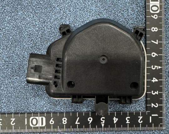
CWTB230X
Feb 07, 2024Sensor for opening and closing doors in cars
Equipment Class
FDS - Part 15 Field Disturbance Sensor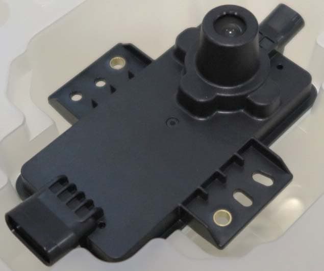
CWTB2211
Dec 26, 2023Automatic access gesture control
Equipment Class
DXX - Part 15 Low Power Communication Device Transmitter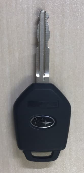
CWTB1G496
Aug 01, 2021KEYLESS ENTRY SYSTEM
Equipment Class
DSC - Part 15 Security/Remote Control Transmitter