CWTUGEA3ACDMA Data Tx Model UGEA3A
ALPS ALPINE CO., LTD.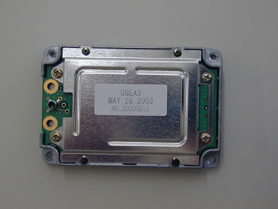
Click to zoom
Application Details
- Equipment Class
- PCB - PCS Licensed Transmitter
- Date of Grant
- Nov 03, 2003
- Application Purpose
- Original Equipment
- Date of Application
- Nov 03, 2003
- Equipment Note
- CDMA Data Tx Model UGEA3A
- Frequency Range
- 1851.25000000 - 1908.75000000
- Company
- ALPS ALPINE CO., LTD.
- Country
- Japan
Documents & Files
Document Text
Text extracted from the exhibit documents filed with the FCC. Open a document above to read the original.
Users Manual
1 ALPS ELECTRIC CO., LTD FCC ID:CWTUGEA3A User Guide Information for ALPS CDMA Data Module Model UGEA3A 1. Introduction: The ALPS, CDMA data module, UGEA3A with Tri mode (AMPS/CDMA/PCS) wireless technology is a radio module that transmits and receives radio signals in accordance with the spectrum regulations for the frequency range of 824 - 849MHz and 1850 -1990MHz The module is intended to be integrated in end-use product, only. For example, Car Navigation systems, such Telematics.. Our customer for end-user shall be instructed in this guide and ALPS installation manual issued by separately. 2. Features 1) High density loading of components gives a compact package measuring 75×50×11mm 2) Designed for the Cellular/PCS network in the North American Market 3) High data rate 153.6kbps(Service Option) 4) Single supply voltage 3.6V 5) Interface to host UART serial (40pin) 6) Comply with TIA/EIA/IS-2000.1-1 The following table shows a major function. Model number Major Function Remarks UGEA3A 1. Frequency bands; 1) AMPS (FM) : 824 - 849MHz 2) CDMA : 824 - 849MHz 3) PCS : 1850 - 1990MHz 2. Output power at antenna terminal: 1) Cellular-CDMA : 22.5dBm +0.5 -2.5 2) PCS -CDMA : 22.5dBm +0.5 -2.5 3) Cellular- AMPS : 25.5dBm +0.5 -2.5 3. External antenna : Maximum Gain : AMPS/CDMA 3.5dBi, PCS 4.5dBi, Impedance : 50 <Alternative> Maximum Gain : AMPS/CDMA 0.3dBi, PCS –0.9dBi Impedance : 50 4. Two Input voltages required. 1) +3.6Vdc +/-0.1V (internal Voltage regulator built in) 2) +3.6Vdc +/-0.1V (requires to stability voltage from outside for cellular and pcs Power Amplifier) 5. Flash memory built in and reference oscillator built in 6. Interface: UART serial connection (40 pins) 1) UART 1 (Data): 115.2 kbps (default )/230.4kbps(max) 2) UART 2 (Monitor): 115.2 kbps (fixed) 7. Forward Data Rate of Air Link: 153.6 +9.6 kbps (max) 8. Reverse Data Rate of Air Link: 76.8 + 9.6 kbps (max) 9. CDMA Voice rate: 9600,4800,2400,1200 bps 10. Control command: AT command 11. Conform to TIA/EIA-98E. TIA/EIA/IS-2000.1-1 HEAD OFFICE :1-7, YUKIGAYA OTSUKA-CHO, OTA-KU, TOKYO, 145-8501 JAPAN PHONE:(03)3726-1211 FACSIMILE:(03)3728-1812 COMMUNICATION DEVICES DIVISION, SOMA PLANT 1-2-1, OKINOUCHI, SOMA-CITY, FUKUSHIMA-PREF., 976-8501, JAPAN PHONE:+81-244-35-1207 FACSIMILE:+81-244-35-1602 2 ALPS ELECTRIC CO., LTD FCC ID:CWTUGEA3A 3. Eligibility requirements for regulatory approval: As a part of regulatory certification, ALPS will provide an approval for the United States of America in the form of module. For regulatory certification for Canada, ALPS UGEA3A has not been certified. Therefore, our customer could not sell the entire product providing ALPS UGEA3A in Canada. The regulatory approval is required for the end-product, where end-user integrates ALPS UGEA3A into entire product in non-compliance to FCC certification conditions of ALPS UGEA3A. The conditions for the certification of ALPS UGEA3A and related information are described below. ALPS wishes that our customer for the end product would contact with us about what conditions of UGEA3A have been certified by FCC. 3.1 Compliance statement to FCC This module complies with part 15 of the FCC rules. Operation is subject to the following conditions: (1) This device may not cause harmful interference, and (2) this device must accept any interference received, including interference that may cause undesired operation. 3.2 RF exposure compliance This module, UGEA3A will be applied as “mobile device”. Because the external antenna of the module is intended to be placed on the location like that persons body (excluding extremities: hands, wrists, feet and legs) be a faraway from the antenna. For example of the location: a top of the roof of an automobile. This equipment complies with FCC radiation exposure limits set forth for at uncontrolled exposure as “mobile device”. Therefore, this module should be installed and operated with minimum distance at least 20cm between the radiator and persons body (excluding extremities: hands, wrists, feet and legs) and must not be co-located or co-operated with any other antenna or transmitter. 3.3 Requirements to end product The following provisions for end product will be required on the FCC regulation. (1) RF exposure compliance ALPS wishes that our customer will instruct to the end user for RF exposure compliance as stated below. This equipment should be installed and operated with minimum distance at least 20cm between the radiator and persons body (excluding extremities: hands, wrists, feet and legs) and must not be co-located or operated with any other antenna or transmitter. (2) External regulator The regulated voltage of 3.6V dc +0.1/-0.1V shall be supplied to cellular Power Amplifier and pcs Power Amplifier equipped within the UGEA3A module through the external regulator which our customer be required to provide into end product. (3) Antenna ALPS wishes that our customer shall use the UGEA3A module without any modifications including antenna. Please refer to table of major function of prior page for the antenna specifications. If customer use a unique antenna, the FCC certification is required for the end product. (4) Markings To satisfy FCC exterior labeling requirements, the following text must be placed on the exterior of the end product. 3 ALPS ELECTRIC CO., LTD FCC ID:CWTUGEA3A Any similar wording that expresses the same meaning may be used. (4) Caution to user for modification The following caution is expressed on the user’s instruction manual. , or Any similar wording that expresses the same meaning may be used. Contains Transmitter Module FCC ID: CWTUGEA3A The changes or modifications not expressly approved by the party responsible for compliance could void the user’s authority to operate the device. The product may cause TV or radio interference, if used in close proximity to receiving equipment. The FCC can require you to stop using the product, if such interference cannot be eliminated.
Attestation Statements
ALPS ELECTRIC CO., LTD FCC ID:CWTUGEA3A Function concerning emergency, E911 When the accident in traffic, a fire, and the crime are found, this module, UGEA3A has the function to dial to 9-1-1 or a local urgent dial. An urgent dial does work with wireless connection as usual manner. When the module is out of coverage area or under the bad wireless condition, it might not be connected to base station.
Cover Letter(s)
America Telecommunications Certification Body Inc. 6731 Whittier Ave, McLean, VA 22101 October 29, 2003 Attention: William H. Graff President and Examining Engineer Subject: Application for CDMA module of Alps Electric Co., Ltd. ATCB ID: ATCB000802 Dear Mr. Graff, We have confirmed your comment which received on October 1, 2003. We completed preparing the new application documents and they have been already uploaded on your web site. Please confirm the following matters. 1) Please provide missing documents as outlined in my separate email of October 1, 2003. For your reference, please see 2.1033 (c) A1) We have already uploaded the following documents on your web site following the documents. Please confirm new documents on your web site. -Parts List -Tune up Procedure (This is included in the Description of modulated systems) -Agent Authorization Letter -Modular Request Letter -Confidentiality Request Letter 2) Please provide voltage and currents in the finals per 2.1033 (c) (8). Ideally this should be a part of the Test Report for all licensed devices. A2) Please discard the previous report and accept the whole new report which is attached below. We measured its electric current and added its data on page 3 of the attached report. Please confirm new documents on your web site. 3) Your Form 731 does not list the power requested for this device. Each emission designation should have a requested, measured power. FYI: Since this is an RF category “Mobile” device, just listing the peak conducted RF power for each requested emission will be satisfactory. A3) We made a new application form 731 that mentions to peak conducted RF power. Please confirm new documents on your web site. 4) Please provide justification for each requested emission designator using the methods as outlined in Part 2 Subpart C, beginning with 2.201. A4) We made up the statement of reason for your comment, please confirm it on your web site. 5) The Users Guide information seems to indicate that the RF Pout can vary significantly, from +23dBm +7/0 for CDMA and +25dBm +2/0. I have concern that this equipment was not tuned up to its maximum RF Pout for testing. Please respond. A5) This test was performed with Maximum Pout mode.. We altered RF Pout because it was not included suitably in Users Guide. 6) Since this device is for a Licensed service, there are protections available to the end user not associated with Unlicensed Part15 transmitters. Therefore the language of 15.19(a)(1) should appear on the device. A6) We prepared a new label including statement of 15 19 (a)(1). Please confirm new documents on your web site. 7) I do not understand the data on pages 18 and 19. If this is a conducted measurement, why is antenna gain appearing in the table? A7) The antenna gain is now deleted. Please confirm it on page 22 and 23 of the attached report. Please confirm new documents on your web site. 8) FYI: In the future, please make your Occupied Bandwidth plots larger-they are very difficult to read and analyze. A8) We understand your suggestion and carry out its way in the next time. 9) It appears that voice modulation (40K0F8W) is adequately presented in analog AMPS mode. However, I see nothing representing wideband data (40K0F1D). It is required that a plot or plots of each requested emission mode be presented for Licensed service. A9) The voice and Wide Band (data) were tested. Please confirm these data on page 15 to 19, 29 to 38 and 47 to 51 on your web site. Voice + SAT mode was the worse- case mode (=it had the worst margin) so that the measurement has been performed. 10) I question the CDMA plots on page 39. They seem to be significantly lower in power than the ones appearing on page 38. Please explain. A10) We retested band edge because we have no reason to get band edge before. If you have any question, Please don’t hesitate to contact us. Sincerely yours, Hisayuki Kioka UL Apex Co., Ltd. EMC Service Dept. Tel: +81-596-24-8116 Fax: +81-596-24-8124 E-mail: [email protected]
External Photos
External Photos ALPS ELECCTRIC CO., LTD. FCC ID: CWTUGEA3A Front Back
Internal Photos
Internal Photos ALPS ELECCTRIC CO., LTD. FCC ID: CWTUGEA3A Front side Cover opened (Front side) Internal Photos ALPS ELECCTRIC CO., LTD. FCC ID: CWTUGEA3A Cover opened (Back side)
Test Report
ALPS ELECTRIC CO., LTD FCC ID:CWTUGEA3A Model: UGEA3A Emission Designation NECESSARY BANDWIDTH - § 2.202 1. Type of Emission: F8W, F1D Necessary Bandwidth: 40K0F1D 40K0F8W Calculation for 40K0F8W (1)Voice + SAT Modulation: Voice is 2.5 kHz and SAT is 6kHz, thus the maximum modulation is M = 6 kHz Deviation: Voice is 12kHz and SAT is 2kHz, thus the maximum deviation is D= 12+2= 14 kHz Bn = 2xM+2xDK with K =1 Bn= 40 kHz (2) Signaling Tone (ST) + SAT Modulation: ST is 10 kHz and SAT is 6kHz, thus the maximum modulation is M = 10 kHz Deviation: ST is 8kHz and SAT is 2kHz, thus the maximum deviation is D= 8+2= 10 kHz Bn = 2xM+2xDK with K =1 Bn= 40 kHz Calculation for 40K0F1D (wide Band Data) Wideband + SAT Modulation: Wideband Data is 10 kHz and SAT is 6kHz, thus the maximum modulation is M = 10 kHz Deviation: Wideband Data is 8kHz and SAT is 2kHz, thus the maximum deviation is D= 8+2 = 10 kHz Bn = 2xM+2xDK with K =1 Bn= 40 kHz Note: Bn: Necessary band width, M: Maximum modulation frequency, D: Peak Frequency modulation. 2. Type of Emission: F9W Necessary bandwidth: 1M23F9W (1) CDMA Mode when operating in a P_REV 5 or less network The CDMA mode is from the TIA/EIA/IS-95B Standard. The transmitted data on baseband is 1.2288Mbps and spread as the chip rate of 1.2288Mcps. Thus the necessary band width is 1.23MHz. (2) CDMA mode when operating in a P_REV 6 or above Network The CDMA mode is from IS-2000.2 Standard. This CDMA data module can only invoke a Spreading Rate 1 operational mode described in table 2.1.3.1.2.1-1 “Access channel modulation parameters for Spreading Rate 1” of the page 24 of the “Description of modulated systems for CDMA data module”, attached separately. The chip rate is the same as IS-95B. Thus, the necessary bandwidth is 1.23MHz, too. HEAD OFFICE :1-7, YUKIGAYA OTSUKA-CHO, OTA-KU, TOKYO, 145-8501 JAPAN PHONE:(03)3726-1211 FACSIMILE:(03)3728-1812 COMMUNICATION DEVICES DIVISION, SOMA PLANT 1-2-1, OKINOUCHI, SOMA-CITY, FUKUSHIMA-PREF., 976-8501, JAPAN PHONE:+81-244-35-1207 FACSIMILE:+81-244-35-1602
Test Report
Test report No. : 23HE0073-HO-1 Page : 11 of 81 Issued date : June 30, 2003 Revised date : October 20, 2003 FCC ID : CWTUGEA3A UL Apex Co., Ltd. Head Office EMC Lab. 4383-326 Asama-cho, Ise-shi, Mie-ken 516-0021 JAPAN Telephone : +81 596 24 8116 Facsimile : +81 596 24 8124 APPENDIX 1: Photographs of test setup Radiated ( Type 1) Test report No. : 23HE0073-HO-1 Page : 12 of 81 Issued date : June 30, 2003 Revised date : October 20, 2003 FCC ID : CWTUGEA3A UL Apex Co., Ltd. Head Office EMC Lab. 4383-326 Asama-cho, Ise-shi, Mie-ken 516-0021 JAPAN Telephone : +81 596 24 8116 Facsimile : +81 596 24 8124 Radiated ( Type 2) Test report No. : 23HE0073-HO-1 Page : 13 of 81 Issued date : June 30, 2003 Revised date : October 20, 2003 FCC ID : CWTUGEA3A UL Apex Co., Ltd. Head Office EMC Lab. 4383-326 Asama-cho, Ise-shi, Mie-ken 516-0021 JAPAN Telephone : +81 596 24 8116 Facsimile : +81 596 24 8124 Conducted
Test Setup Photos
Test report No. : 23HE0073-HO-1 Page : 11 of 65 Issued date : June 30, 2003 FCC ID : CWTUGEA3A UL Apex Co., Ltd. Head Office EMC Lab. 4383-326 Asama-cho, Ise-shi, Mie-ken 516-0021 JAPAN Telephone : +81 596 24 8116 Facsimile : +81 596 24 8124 APPENDIX 1: Photographs of test setup Radiated ( Type 1) Test report No. : 23HE0073-HO-1 Page : 12 of 65 Issued date : June 30, 2003 FCC ID : CWTUGEA3A UL Apex Co., Ltd. Head Office EMC Lab. 4383-326 Asama-cho, Ise-shi, Mie-ken 516-0021 JAPAN Telephone : +81 596 24 8116 Facsimile : +81 596 24 8124 Radiated ( Type 2) Test report No. : 23HE0073-HO-1 Page : 13 of 65 Issued date : June 30, 2003 FCC ID : CWTUGEA3A UL Apex Co., Ltd. Head Office EMC Lab. 4383-326 Asama-cho, Ise-shi, Mie-ken 516-0021 JAPAN Telephone : +81 596 24 8116 Facsimile : +81 596 24 8124 Conducted
Contact Information
Applicant
Yuji Ouchi
Technical Contact
UL Apex Co. Ltd.Hiroka Umeyama
+81 596 24 8116
4883-326 Asama-cho · Ise-shi, Mie-ken · Japan
Technical Specifications
| # | Rule Parts | Frequency Range | Power Output | Emission | Tolerance |
|---|---|---|---|---|---|
| 4 | 24E | 1.85 GHz - 1.91 GHz | 200.00 mW | 1M25F9W | 2.5 ppm |
Other Applications from ALPS ALPINE CO., LTD.
CWTUMNZ1A2
Oct 06, 20245G Communication Module
Equipment Class
PCB - PCS Licensed TransmitterCWTB2311
Apr 09, 2024Automatic access gesture control
Equipment Class
DXX - Part 15 Low Power Communication Device Transmitter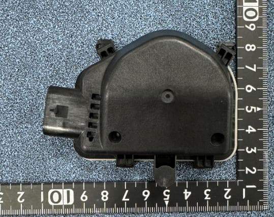
CWTB230X
Feb 07, 2024Sensor for opening and closing doors in cars
Equipment Class
FDS - Part 15 Field Disturbance Sensor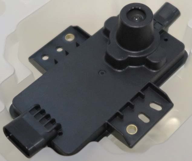
CWTB2211
Dec 26, 2023Automatic access gesture control
Equipment Class
DXX - Part 15 Low Power Communication Device Transmitter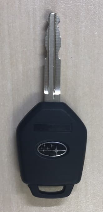
CWTB1G496
Aug 01, 2021KEYLESS ENTRY SYSTEM
Equipment Class
DSC - Part 15 Security/Remote Control Transmitter