CWTUGZZCBluetooth Module 2.1 + EDR with Antenna
ALPS ALPINE CO., LTD.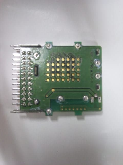
Click to zoom
Application Details
- Equipment Class
- DSS - Part 15 Spread Spectrum Transmitter
- Date of Grant
- Sep 26, 2012
- Application Purpose
- Original Equipment
- Date of Application
- Sep 19, 2012
- Equipment Note
- Bluetooth Module 2.1 + EDR with Antenna
- Frequency Range
- 2402.00000000 - 2480.00000000
- Company
- ALPS ALPINE CO., LTD.
- Country
- Japan
Documents & Files
Document Text
Text extracted from the exhibit documents filed with the FCC. Open a document above to read the original.
Users Manual
Antenna Information Section1. Antenna Assembly Specification Antenna Assembly Summary: Antenna part numberManufacture Antenna Type Peak Gain Printed Antenna ALPS ELECTRIC CO., LTD. λ/4 PIFA 0.6dBi DETAIL:a Section2.Radiation characteristics of antenna in free space 2402-2480 radiation characteristic Z-X Plane Frequency: 2402MHz Frequency: 2441MHz Center Frequency [MHz] 2402 Horizontal Peak [dBi] 0.0 Vertical Peak [dBi] -13.1 Center Frequency [MHz] 2441 Horizontal Peak [dBi] 0.0 Vertical Peak [dBi] -12.5 -40 -30 -20 -10 0 0 30 60 90 120 150 180 -150 -120 -90 -60 -30 ZX-V ZX-H Unit : dBi -40 -30 -20 -10 0 0 30 60 90 120 150 180 -150 -120 -90 -60 -30 ZX-V ZX-H Unit : dBi -90° -X 180° +90° 0° +X +Z -Z -90° -X 180° +90° 0° +X +Z -Z -90° -X 180° +90° 0° +X +Z -Z -90° -X 180° +90° 0° +X +Z -Z Frequency: 2480MHz Z-Y Plane Center Frequency [MHz] 2480 Horizontal Peak [dBi] 0.2 Vertical Peak [dBi] -14.5 Center Frequency [MHz] 2402 Horizontal Peak [dBi] 0.0 Vertical Peak [dBi] -3.5 -40 -30 -20 -10 0 0 30 60 90 120 150 180 -150 -120 -90 -60 -30 ZY -V ZY -H Unit : dBi -40 -30 -20 -10 0 0 30 60 90 120 150 180 -150 -120 -90 -60 -30 ZX-V ZX-H Unit : dBi -90° -X 180° +90° 0° +X +Z -Z -90° -X 180° +90° 0° +X +Z -Z -90° -Y 180° +90° 0° +Z +Y -Z -90° -Y 180° +90° 0° +Z +Y -Z Frequency: 2441MHz Frequency: 2480MHz Center Frequency [MHz] 2441 Horizontal Peak [dBi] 0.3 Vertical Peak [dBi] -3.1 Center Frequency [MHz] 2480 Horizontal Peak [dBi] 0.2 Vertical Peak [dBi] -3.4 -40 -30 -20 -10 0 0 30 60 90 120 150 180 -150 -120 -90 -60 -30 ZY -V ZY -H Unit : dBi -40 -30 -20 -10 0 0 30 60 90 120 150 180 -150 -120 -90 -60 -30 ZY -V ZY -H Unit : dBi -90° -Y 180° +90° 0° +Z +Y -Z -90° -Y 180° +90° 0° +Z +Y -Z -90° -Y 180° +90° 0° +Z +Y -Z -90° -Y 180° +90° 0° +Z +Y -Z Y-X Plane Frequency: 2402MHz Frequency: 2441MHz Center Frequency [MHz] 2402 Horizontal Peak [dBi] -4.3 Vertical Peak [dBi] 0.4 Center Frequency [MHz] 2441 Horizontal Peak [dBi] -3.8 Vertical Peak [dBi] 0.6 -40 -30 -20 -10 0 0 30 60 90 120 150 180 -150 -120 -90 -60 -30 YX-V YX-H Unit : dBi -40 -30 -20 -10 0 0 30 60 90 120 150 180 -150 -120 -90 -60 -30 YX-V YX-H Unit : dBi -90° -X 180° +90° 0° +X +Y -Y -90° -X 180° +90° 0° +X +Y -Y -90° -X 180° +90° 0° +X +Y -Y -90° -X 180° +90° 0° +X +Y -Y Frequency: 2480MHz Center Frequency [MHz] 2480 Horizontal Peak [dBi] -4.7 Vertical Peak [dBi] 0.4 -40 -30 -20 -10 0 0 30 60 90 120 150 180 -150 -120 -90 -60 -30 YX-V YX-H Unit : dBi -90° -X 180° +90° 0° +X +Y -Y -90° -X 180° +90° 0° +X +Y -Y
Users Manual
Bluetooth ® Module UGZZC Installation Manual Copyright© 2012 ALPS ELECTRIC CO., LTD 1/2 1. This device complies with Part 15 of FCC Rules and Industry Canada license-exempt RSS standard(s). Operation is subject to the following two conditions: (1) this device may not cause interference, and (2) this device must accept any interference, including interference that may cause undesired operation of this device. 2. If the FCC ID written in the label which is stuck on the surface of the device can not seen from out side when it’s installed in a customer’s product, following indication is necessary to be showed on the product in which the device is installed. And the indication is also necessary to be written in a user manual of the customer’s product. “Contains Transmitter Module FCC ID: CWTUGZZC”, or “Contains FCC ID: CWTUGZZC” 3. If the IC Number written in the label which is stuck on the surface of the device can not seen from out side when it’s installed in a customer’s product, following indication is necessary to be showed on the product in which the device is installed. And the indication is also necessary to be written in a user manual of the customer’s product. “Contains Transmitter Module IC: 1788F-UGZZC”, or “Contains IC: 1788F-UGZZC” 4.Co-locating with another transmitter may require some consideration for RX Exposure. 5. Module operating notice Input power: DC Voltage 3.3V (for IF) / 1.5V’ (for operation) Connector: Board to Board connecter with 24pins (IRISO ELECTRONICS :9162S-24B-T) Interconnecting requirements: The position is confirmed and shall insert in parallel. When inserting it excessive power shall not be given. FCC WARNING Changes or modifications not expressly approved by the party responsible for compliance could void the user’s authority to operate the equipment. Note: This equipment has been tested and found to comply with the limits for a Class B digital device, pursuant to part 15 of the FCC Rules. These limits are designed to provide reasonable protection against harmful interference in a residential installation. This equipment generates uses and can radiate radio frequency energy and, if not installed and used in accordance with the instructions, may cause harmful interference to radio communications. However, there is no guarantee that interference will not occur in a particular installation. Bluetooth ® Module UGZZC Installation Manual Copyright© 2012 ALPS ELECTRIC CO., LTD 2/2 If this equipment does cause harmful interference to radio or television reception, which can be determined by turning the equipment off and on, the user is encouraged to try to correct the interference by one or more of the following measures: Reorient or relocate the receiving antenna. Increase the separation between the equipment and receiver. Connect the equipment into an outlet on a circuit different from that to which the receiver is connected. Consult the dealer or an experienced radio/TV technician for help.
Cover Letter(s)
Federal Communications Commission 7435 Oakland Mills Road Columbia, MD 21046 Strasskirchen, 19.09.2012 Request for a Modular Approval - FCC ID: CWTUGZZC Dear Sirs, Our client’s module with the above FCC ID is seeking FCC authorization as a Modular transmitter. The requirements of the FCC Public notice DA00-1407 and KDB 996369 are met. Please see the following comments: Please contact us if you have any additional questions. Item Requirements EUT 1 Have its own RF shielding Device is equipped with metal shielding to cover RF section. Refer to external photos 2 Have buffered modulation/data inputs (if such inputs are provided), The EUT has buffered data inputs. 3 Have it own power supply regulation 3.3 VDC. Refer to Block diagram 4 Meet the antenna requirements of Section 15.203 The antenna is an integral type and there is no antenna connector. Therefore, the modular transmitter does not regard to section 15.203. 5 Be tested in a stand-alone configuration, i.e., the antenna, AC or DC power and data input/output lines must be connected to the module but, the module must not be inside another case during testing Device was tested in a stand-alone configuration on a Test Jig. Refer to setup photos & internal photos. 6 Be labelled with its own FCC ID number, and if the FCC ID is not visible when the module is installed inside another device, then the outside of the device into which the module is installed must also display a label referring to the enclosed module. The module has its own label. Refer to FCC ID label format and location file. 7 The modular transmitter is manufactured so that the user cannot influence the operation of the transmitter that will operate outside of the scope of the regulations. The module as manufactured is completely controlled by the onboard processor There are no influences to the operation of the transmitter the end user can induce that will operate the module outside of scope of the regulations. 8 Compliance with RF exposure requirements is the responsibility of the grantee and will be addressed for all final host configurations Compliance with RF exposure requirements Thomas Ring / Manager Certification / mikes-testingpartners gmbh Ohmstr. 2-4, 94342 Strasskirchen, Germany Phone: +49 9424 9481 214, Email: [email protected]
Cover Letter(s)
Request for Confidentiality Date: 19.09.2012 Subject: Confidentiality Request for: FCC ID: CWTUGZZC IC: 1788F-UGZZC ______ Pursuant to FCC 47 CRF 0.457(d) and 0.459 and IC RSP-100, Section 10, the applicant requests that a part of the subject FCC application be held confidential. Type of Confidentiality Requested Exhibit Short Term Permanent Block Diagrams Short Term External Photos Short Term Permanent* 1 Internal Photos Short Term Permanent Operation Description/Theory of Operation Short Term Permanent Parts List & Placement/BOM Short Term Permanent Tune-Up Procedure Short Term Permanent Schematics Short Term Test Setup Photos Short Term Permanent* User’s Manual *Note: ______(Insert Explanation as Necessary)______ Alps Electric Co., Ltd. has spent substantial effort in developing this product and it is one of the first of its kind in industry. Having the subject information easily available to "competition" would negate the advantage they have achieved by developing this product. Not protecting the details of the design will result in financial hardship. Permanent Confidentiality: The applicant requests the exhibits listed above as permanently confidential be permanently withheld from public review due to materials that contain trade secrets and proprietary information not customarily released to the public. Short-Term Confidentiality: The applicant requests the exhibits selected above as short term confidential be withheld from public view for a period of (0) days from the date of the Grant of Equipment Authorization and prior to marketing. This is to avoid premature release of sensitive information prior to marketing or release of the product to the public. Applicant is also aware that they are responsible to notify ACB in the event information regarding the product or the product is made available to the public. ACB will then release the documents listed above for public disclosure pursuant to FCC Public Notice DA 04-1705. NOTE for Industry Canada Applications: The applicant understands that until such time that IC distinguishes between Short Term and Permanent Confidentiality, either type of marked exhibit above will simply be marked Confidential when submitted to IC. Sincerely, By: Manager Certification Thomas Ring 1 - The asterisked items (*) require further justification before permanent confidentiality will be allowed. These also currently require review by the FCC under their Permit-But-Ask policy before the grant is issued and can delay completion of an application. Further justification should be added to the note above. One such example for a potted device would be: “The EUT is FULLY potted using a non-removable epoxy based material. Removal of potting material causes irreparable damage to internal circuitry. See photographs exhibits that outline the device before and after potting.”
External Photos
Front Side view Reverse Side view
External Photos
Front Side view Reverse Side view UGZZC-G01A Module Antenna Pattern Antenna Pattern
Internal Photos
Internal view (Removed shield cover)
Test Report
FCC ID: CWTUGZZC / IC:1788F-UGZZC mikes-testingpartners gmbh File No. T36209-00-04TK, page 1 of 95 Ohmstrasse 2-4 94342 STRASSKIRCHEN GERMANY Tel.: +49(0)9424-94810 Fax: +49(0)9424-9481240 Rev. No. 1.2, 30.6.2011 EMI − T E S T R E P O R T - FCC Part 15.247, RSS210 - Test Report No. : T36209-00-04TK 2012-09-26 ______________________________________________________________________________________________ Date of issue Type / Model Name : UGZZC-G Product Description : Bluetooth Module 2.1 + EDR with Antenna Applicant : ALPS Electric Co., Ltd Address : 6-3-36 Furukawanakazato : Osaki-city Miyagi-pref 989-6181, JAPAN Manufacturer : ALPS Electric Co., Ltd Address : 6-3-36 Furukawanakazato : Osaki-city Miyagi-pref 989-6181, JAPAN Licence holder : ALPS Electric Co., Ltd Address : 6-3-36 Furukawanakazato : Osaki-city Miyagi-pref 989-6181, JAPAN Test Result according to the standards listed in clause 1 test standards: POSITIVE The test report merely corresponds to the test sample. It is not permitted to copy extracts of these test results without the written permission of the test laboratory. FCC ID: CWTUGZZC / IC:1788F-UGZZC mikes-testingpartners gmbh File No. T36209-00-04TK, page 2 of 95 Ohmstrasse 2-4 94342 STRASSKIRCHEN GERMANY Tel.: +49(0)9424-94810 Fax: +49(0)9424-9481240 Rev. No. 1.2, 30.6.2011 Contents 1 TEST STANDARDS 3 2 SUMMARY 4 Test result summery 4 2.1 3 EQUIPMENT UNDER TEST 7 Photo documentation of the EUT 7 3.1 Power supply system utilised 10 3.2 Short description of the EUT 10 3.3 4 TEST ENVIRONMENT 11 Address of the test laboratory 11 4.1 Environmental conditions 11 4.2 Statement of the measurement uncertainty 11 4.3 Measurement protocol for FCC and IC 11 4.4 Determination of worst case measurement conditions 12 4.5 5 TEST CONDITIONS AND RESULTS 13 Conducted emissions 13 5.1 Emission bandwidth 19 5.2 Occupied bandwidth 26 5.3 Maximum peak output power conducted 33 5.4 Spurious emissions conducted 35 5.5 Band edge compliance 67 5.6 Radiated emissions in restricted bands 72 5.7 Pseudorandom frequency hopping sequence 78 5.8 Equal hopping frequency use 78 5.9 Receiver input bandwidth 79 5.10 Correction for pulsed operation (duty cycle) 79 5.11 Dwell time 80 5.12 Carrier frequency separation 81 5.13 Number of hopping channels 84 5.14 Antenna application 85 5.15 Maximum permissible exposure (MPE) 85 5.16 Receiver conducted emissions 87 5.17 Receiver radiated emissions 92 5.18 6 USED TEST EQUIPMENT AND ACCESSORIES 95 FCC ID: CWTUGZZC / IC:1788F-UGZZC mikes-testingpartners gmbh File No. T36209-00-04TK, page 3 of 95 Ohmstrasse 2-4 94342 STRASSKIRCHEN GERMANY Tel.: +49(0)9424-94810 Fax: +49(0)9424-9481240 Rev. No. 1.2, 30.6.2011 1 TEST STANDARDS The tests were performed according to following standards: FCC Rules and Regulations Part 15, Subpart A - General (September, 2011) Part 15, Subpart A, Section 15.31 Measurement standards Part 15, Subpart A, Section 15.33 Frequency range of radiated measurements Part 15, Subpart A, Section 15.35 Measurement detector functions and bandwidths FCC Rules and Regulations Part 15, Subpart C - Intentional Radiators (September, 2011) Part 15, Subpart C, Section 15.203 Antenna requirement Part 15, Subpart C, Section 15.204 External radio frequency power amplifiers and antenna modifications Part 15, Subpart C, Section 15.205 Restricted bands of operation Part 15, Subpart C, Section 15.207 Conducted limits Part 15, Subpart C, Section 15.209 Radiated emission limits, general requirements Part 15, Subpart C, Section 15.212 Modular Transmitters Part 15, Subpart C, Section 15.247 Operation within the bands 902 - 928 MHz, 2400 - 2483.5 MHz and 5725 - 5850 MHz FCC Rules and Regulations Part 1, Subpart I - Procedures Implementing the National Environmental Policy Act of 1969 Part 1, Subpart I, Section 1.1310 Radiofrequency radiation exposure limits Part 1, Subpart 2, Section 2.1093 Radiofrequency radiation exposure evaluation: portable device OET Bulletin 65, 65A, 65B, 65C Edition 97-01, August 1997 – Evaluating Compliance with FCC Guidelines for Human Exposure to Radio Frequency Electromagnetic Fields. ANSI C63.4: 2003 Methods of Measurement of Radio-Noise Emissions from Low- Voltage Electrical and Electronic Equipment in the Range of 9 kHz to 40 GHz. ANSI C95.1: 2005 IEEE Standard for Safety Levels with respect to Human Exposure to Radio Frequency Electromagnetic Fields, 3 kHz to 300 GHz CISPR 16-4-2: 2003 Uncertainty in EMC measurement CISPR 22: 2005 Information technology equipment EN 55022: 2006 DA 00-705 Filing and measurement guidelines for FHSS systems FCC ID: CWTUGZZC / IC:1788F-UGZZC mikes-testingpartners gmbh File No. T36209-00-04TK, page 4 of 95 Ohmstrasse 2-4 94342 STRASSKIRCHEN GERMANY Tel.: +49(0)9424-94810 Fax: +49(0)9424-9481240 Rev. No. 1.2, 30.6.2011 2 SUMMARY Test result summery 2.1 Bluetooth device using frequency hopping: Operating in the 2400 MHz – 2483.5 MHz band: FCC Rule Part RSS Rule Part Description Result 15.207(a) RSS Gen, 7.2.4. AC power line conducted emissions passed 15.247(a)(1) RSS210, A8.1(a) 20 dB EBW passed 15.247(a)(1) RSS-210, A8.1(b) Channel separation passed 15.247(a)(1) RSS-210, A8.1(d) Dwell time passed 15.247(b)(1) RSS-210, A8.4(2) Peak power passed 15.247(d) RSS-210, A8.5 Spurious emissions passed 15.247(d) RSS-210, A8.5 Out-of-band emission, radiated passed 15.247(d) RSS-Gen, 7.2.2 Emissions in restricted bands passed 15.247(e) RSS-210, A8.2(b) Hopping sequence passed 15.247(a) RSS-210, A8.1(b) Receiver input bandwith passed 15.247(a) RSS-210, A8.1(d) Number of hopping channels passed 15.247(a) - Equal hopping frequency use passed 15.35(c) RSS-Gen, 4.5 Pulsed operation not applicable 15.247(i) RSS 102, 2.5.2 MPE passed 15.247(b)(4) RSS-Gen, 7.1.2 Antenna requirement passed RSS-Gen, 7.2.6 Transmitter frequency stability not applicable OET Bulletin 65 RSS102, 3.2 Co-location, Co-transmission not applicable The mentioned RSS Rule Parts in the above table are related to: RSS Gen, Issue 3, December 2…
Text truncated - open the document above for the full version.
Test Setup Photos
FCC ID: CWTUGZZC / IC:1788F-UGZZC mikes-testingpartners gmbh File No. T36209-00-04TK, page 13 of 95 Ohmstrasse 2-4 94342 STRASSKIRCHEN GERMANY Tel.: +49(0)9424-94810 Fax: +49(0)9424-9481240 Rev. No. 1.2, 30.6.2011 5 T E S T C O N D I T I O N S A N D R E S U L T S Conducted emissions 5.1 For test instruments and accessories used see section 6 Part A 4. Legend for tables: QP-L ... QuasiPeak reading including correction factor AV-L ... Average reading including correction factor D-Limit... Measured value to limit delta (margin) 5.1.1 Description of the test location Test location: Shielded Room 2 5.1.2 Photo documentation of the test set-up 5.1.3 Applicable standard According to FCC Part 15C, Section 15.207(a): Intentional radiator that is designed to be connected to the public utility (AC) power line, the radio frequency voltage that is conducted back onto th AC power line on any frequency or frequencies within the band 150 kHz to 30 MHz. FCC ID: CWTUGZZC / IC:1788F-UGZZC mikes-testingpartners gmbh File No. T36209-00-04TK, page 19 of 95 Ohmstrasse 2-4 94342 STRASSKIRCHEN GERMANY Tel.: +49(0)9424-94810 Fax: +49(0)9424-9481240 Rev. No. 1.2, 30.6.2011 Emission bandwidth 5.2 For test instruments and accessories used see section 6 Part MB. 5.2.1 Description of the test location Test location: Shielded Room 4 5.2.2 Photo documentation of the test set-up FCC ID: CWTUGZZC / IC:1788F-UGZZC mikes-testingpartners gmbh File No. T36209-00-04TK, page 26 of 95 Ohmstrasse 2-4 94342 STRASSKIRCHEN GERMANY Tel.: +49(0)9424-94810 Fax: +49(0)9424-9481240 Rev. No. 1.2, 30.6.2011 Occupied bandwidth 5.3 For test instruments and accessories used see section 6 Part MB. 5.3.1 Description of the test location Test location: Shielded Room 4 5.3.2 Photo documentation of the test set-up 5.3.1 Applicable standard According to RSS-Gen, 4.6.1: When an occupied bandwidth value is not specified in the applicable RSS, the transmitted signal bandwidth to be reported is to be its 99 % emission bandwidth, as calculated or measured. 5.3.2 Description of Measurement The bandwidth was measured with the function “bandwidth measurement” of the spectrum analyser. The EUT is connected via suitable attenuator at the spectrum analyser. The measurement is repeated for every different modulation standard of the EUT and recorded. Spectrum analyser settings: RBW: 100 kHz, VBW: 300 kHz, Detector: Peak, Sweep time: auto FCC ID: CWTUGZZC / IC:1788F-UGZZC mikes-testingpartners gmbh File No. T36209-00-04TK, page 33 of 95 Ohmstrasse 2-4 94342 STRASSKIRCHEN GERMANY Tel.: +49(0)9424-94810 Fax: +49(0)9424-9481240 Rev. No. 1.2, 30.6.2011 Maximum peak output power conducted 5.4 5.4.1 Description of the test location For test instruments and accessories used see section 6 Part CPC 3. Test location: Shielded Room 4 5.4.2 Photo documentation of the test set-up 5.4.3 Applicable standard According to FCC Part 15C, Section 15.247(a)(1): The maximum peak output power of an intentional radiator shall not exceed the limit defined in dependency of the channel separation and of the number of hopping channels. 5.4.4 Description of Measurement A spectrum analyser is connected to the output of the transmitter via a suitable attenuator while EUT is operating in transmit mode using the assigned frequency according to DA 00-705. The cable loss and the 10 dB inline attenuator is summed up to a resulting attenuation of 11.4 dB which gives a correction factor. The correction factor is taken into account as offset during the measurements and is therefore not evident in the following tables. Analyser settings: RBW: 3 MHz, VBW ≥ RBW, Detector: Max peak, Trace: Max hold, Sweep time: auto FCC ID: CWTUGZZC / IC:1788F-UGZZC mikes-testingpartners gmbh File No. T36209-00-04TK, page 35 of 95 Ohmstrasse 2-4 94342 STRASSKIRCHEN GERMANY Tel.: +49(0)9424-94810 Fax: +49(0)9424-9481240 Rev. No. 1.2, 30.6.2011 Spurious emissions conducted 5.5 For test instruments and accessories used see section 6 Part SEC1, SEC2 and SEC3. 5.5.1 Description of the test location Test location: Shielded Room 4 5.5.2 Applicable standard According to FCC Part 15C, Section 15.247(d): In any 100 kHz bandwidth outside the frequency bands 2400 – 2483.5 MHz and 5725 – 5850 MHz, the digitally modulated radio frequency power that is produced by the intentional radiator shall be at least 20 dB below that in the 100 kHz bandwidth within the band that contains the highest level of the desired power, based on either an RF conducted or an radiated measurement. Attenuation below the general limits specified in Section 15.209(a) is not required. 5.5.3 Description of Measurement A spectrum analyser is connected to the output of the transmitter via a suitable attenuator while EUT is operating in transmit mode using the assigned frequency according to DA 00-705. Spectrum analyser settings: RBW: 100 kHz, VBW: 300 kHz, Detector: Max peak, Trace: Max hold, Sweep: auto 5.5.4 Photo documentation of the test set-up FCC ID: CWTUGZZC / IC:1788F-UGZZC mikes-testingpartners gmbh File No. T36209-00-04TK, page 67 of 95 Ohmstrasse 2-4 94342 STRASSKIRCHEN GERMANY Tel.: +49(0)9424-94810 Fax: +49(0)9424-9481240 Rev. No. 1.2, 30.6.2011 Band edge compliance 5.6 For test instruments and accessories used see section 6 Part SEC3. 5.6.1 Description of the test location Test location: Shielded Room 4 5.6.2 Applicable standard According to FCC Part 15C, Section 15.247(d): In any 100 kHz bandwidth outside the frequency bands 2400 – 2483.5 MHz and 5725 – 5850 MHz, the digitally modulated radio frequency power that is produced by the intentional radiator shall be at least 20 dB below that in the 100 kHz bandwidth within the band that contains the highest level of the desired power, based on either an RF conducted or an radiated measurement. Attenuation below the general limits specified in Section 15.209(a) is not required. 5.6.3 Description of Measurement A spectrum analyser is connected to the output of the transmi…
Text truncated - open the document above for the full version.
Contact Information
Applicant
Yuji Ouchi
Technical Contact
Test Firm
CSA Group Bayern GmbHThomas Weise
Technical Specifications
| # | Rule Parts | Frequency Range | Power Output |
|---|---|---|---|
| 1 | 15C | 2.40 GHz - 2.48 GHz | 1.80 mW |
Other Applications from ALPS ALPINE CO., LTD.
CWTUMNZ1A2
Oct 06, 20245G Communication Module
Equipment Class
PCB - PCS Licensed TransmitterCWTB2311
Apr 09, 2024Automatic access gesture control
Equipment Class
DXX - Part 15 Low Power Communication Device Transmitter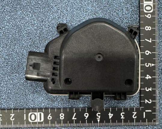
CWTB230X
Feb 07, 2024Sensor for opening and closing doors in cars
Equipment Class
FDS - Part 15 Field Disturbance Sensor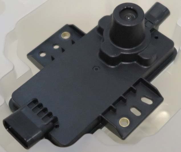
CWTB2211
Dec 26, 2023Automatic access gesture control
Equipment Class
DXX - Part 15 Low Power Communication Device Transmitter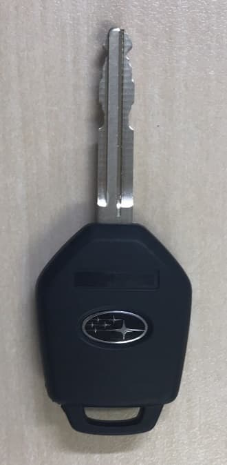
CWTB1G496
Aug 01, 2021KEYLESS ENTRY SYSTEM
Equipment Class
DSC - Part 15 Security/Remote Control Transmitter