CWTUGZZF2BLUETOOTH(TM) Module
ALPS ALPINE CO., LTD.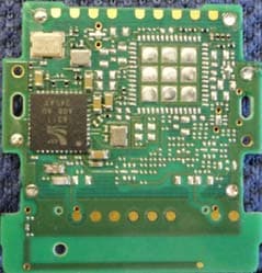
Click to zoom
Application Details
- Equipment Class
- DSS - Part 15 Spread Spectrum Transmitter
- Date of Grant
- Sep 11, 2013
- Application Purpose
- Original Equipment
- Date of Application
- Sep 11, 2013
- Equipment Note
- BLUETOOTH(TM) Module
- Frequency Range
- 2402.00000000 - 2480.00000000
- Company
- ALPS ALPINE CO., LTD.
- Country
- Japan
Documents & Files
Document Text
Text extracted from the exhibit documents filed with the FCC. Open a document above to read the original.
Users Manual
DSGD. CHKD. APPD. TITLE HARDWARE SPECIFICATION SYMB. DATA OR NO. APPD. CHKD.DSGD. Proprietary Information Confidential page 31 Copyright 2013 ALPS ELECTRIC CO.,LTD. 5.Aug.2013 / UGZZF-2 Specification Rev.0.0.1 UGZZF-2 9. REGIONAL REGULATIONS This Product has taken the following regulatory modular approval by the antenna described in the chapter 9.1, 9.2, 9.3 and 9.4. a) Japanese Radio Law Certification [Japan] Article 2-1of the Certification Ordinance 19 b) FCC and IC Certification [North America and Canada] FCC Part15 SubpartC RSS-210 c) R&TTE Directive Certification [EU] EN 300 328 V1.8.1 EN 301 489-1 V1.9.2 EN 301 489-17 V2.2.1 EN62479:2010 EN60950-1:2006+A11:2009+A1:2010+A12:2011 Customer can certify their product without RF test for regulatory RF certification, if following conditionsare satisfied. Otherwise additional RF certifications are necessary. 1) Antenna type (shape, size, etc.) shall be similar with the tested antenna by ALPS. 2) Antenna gain shall be lower than the tested antenna by ALPS. 3) EMC performance shall satisfy the condition of each certification. These requirements shall be guaranteed by the customer. FCC requirements: If the FCC ID written in the label which is stuck on the surface of the device can not seen from out side when it’s installed in a customer’s product, following indication is necessary to be showed on the product in which the device is installed. And the indication is also necessary to be written in a user manual of the customer’s product. “Contains Transmitter Module FCC ID: CWTUGZZF2”, or “Contains FCC ID: CWTUGZZF2“ FCC CAUTION Changes or modifications not expressly approved by the party responsible for compliance could void the user’s authority to operate the equipment. Note: This equipment has been tested and found to comply with the limits for a Class B digital device, pursuant to part 15 of the FCC Rules. These limits are designed to provide reasonable protection against harmful interference in a residential installation. This equipment generates, uses and can radiate radio frequency energy and, if not installed and used in accordance with the instructions, may cause harmful interference to radio communications. However, there is no guarantee that interference will not occur in a particular installation. If this equipment does cause harmful interference to radio or television reception, which can be determined by turning the equipment off and on, the user is encouraged to try to correct the interference by one or more of the following measures: —Reorient or relocate the receiving antenna. —Increase the separation between the equipment and receiver. —Connect the equipment into an outlet on a circuit different from that to which the receiver is connected. —Consult the dealer or an experienced radio/TV technician for help. This transmitter must not be co-located or operated in conjunction with any other antenna or transmitter. DSGD. CHKD. APPD. TITLE HARDWARE SPECIFICATION SYMB. DATA OR NO. APPD. CHKD.DSGD. Proprietary Information Confidential page 32 Copyright 2013 ALPS ELECTRIC CO.,LTD. 5.Aug.2013 / UGZZF-2 Specification Rev.0.0.1 UGZZF-2 IC requirements: If the IC Number written in the label which is stuck on the surface of the device can not seen from out side when it’s installed in a customer’s product, following indication is necessary to be showed on the product in which the device is installed. And the indication is also necessary to be written in a user manual of the customer’s product. “Contains Transmitter Module IC: 1788F-UGZZF2”, or “Contains IC: 1788F-UGZZF2“ This device complies with Industry Canada licence-exempt RSS standard(s). Operation is subject to the following two conditions: (1) this device may not cause interference, and (2) this device must accept any interference,including interference that may cause undesired operation of the device. Le présent appareil est conforme aux CNR d'Industrie Canada applicables aux appareils radio exempts de licence. L'exploitation est autorisée aux deux conditions suivantes : (1) l'appareil ne doit pas produire de brouillage, et (2) l'utilisateur de l'appareil doit accepter tout brouillage radioélectrique subi, même si le brouillage est susceptible d'en compromettre le fonctionnement. This Under Industry Canada regulations, this radio transmitter may only operate using an antenna of a type and maximum(or lesser) gain approved for the transmitter by Industry Canada. To reduce potential radio interference to other users, the antenna type and its gain should be so chosen that the equivalent isotropically radiated power (e.i.r.p.) is not more than that necessary for successful communication. Conformément à la réglementation d'Industrie Canada, le présent émetteur radio peut fonctionner avec une antenne d'un type et d'un gain maximal (ou inférieur) approuvé pour l'émetteur par Industrie Canada. Dans le but de réduire les risques de brouillage radioélectrique à l'intention des autres utilisateurs, il faut choisir le type d'antenne et son gain de sorte que la puissance isotrope rayonnée équivalente (p.i.r.e.) ne dépasse pas l'intensité nécessaire à l'établissement d'une communication satisfaisante. FCC and IC common requirements: This device complies with Part 15 of FCC Rules and Industry Canada licence-exempt RSS standard(s). Operation is subject to the following two conditions: (1) this device may not cause interference, and (2) this device must accept any interference, including interference that may cause undesired operation of this device. Le présent appareil est conforme aux la partie 15 des règles de la FCC et CNR d'Industrie Canada applicables aux appareils radio exempts de licence. L'exploitation est autorisée aux deux conditions suivantes : (1) l'appareil ne doit pas produire de brouillage, et (2) l'utilisateur de l'appareil doit accepter tout brouillage radioélectrique subi, même si le brouillage est susceptible d'en compromettre le fonctionnement. This equipment…
Text truncated - open the document above for the full version.
External Photos
Internal Printed Antenna for Bluetooth Antenna connection connector 1. External antenna connection of Dipole Antenna 2. External antenna connection of PIFA Antenna 3. External antenna connection of PIFA Antenna 4. Antenna connection of Internal Antenna Shield cover side view Bottom side view Internal view (Removed shield cover) UGZZF-2 Bluetooth only module picture Printed Antenna for BLUETOOTH™ Printed Antenna for BLUETOOTH™ Chip Antenna for BLUETOOTH™ Printed Antenna for BLUETOOTH™
ID Label/Location Info
Proprietary Information Confidential page 42 Copyright 2013 ALPS ELECTRIC CO.,LTD. 5.Aug.2013 / UGZZF-2_Specification_Rev0.0.1 DSGD. CHKD. APPD. TITLE PACKING SPECIFICATION SYMB. DATA OR NO. APPD. CHKD.DSGD. UGZZF-2 1-4. Storage Conditions The following conditions shall be kept in storage this product. 1. TEMPERATUER : 0~40°C 2. HUMIDITY : 45~85%RH 3 . STORAGE TIME : 6 MONTH MAX 2. LABEL DESCRIPTION Description Composition ALPS MODEL No. The ten digits “UGZZF□□□□□” ALPS LOT No. The seven digits “ □□□□□□□” Specification modification No. Production line Day Code Month Code JanFebMarAprMay Jun 1 2 3 4 5 6 Jul AugSepOctNov Dec 7 8 9 O N D Year Code CY2011 CY2012 CY2013 1 2 3 Note: Last number of Christian year. QR CODE Customer Model No. _ ALPS Model No. _ ALPS Lot No.
Internal Photos
Internal Printed Antenna for Bluetooth Antenna connection connector Shield cover side view Bottom side view nternal view (Removed shield cover) UGZZF-2 Bluetooth only module picture
RF Exposure Info
UL Japan, Inc. Shonan EMC Lab. 1-22-3 Megumigaoka, Hiratsuka-shi, Kanagawa-ken, 259-1220 JAPAN Telephone : +81 463 50 6400 Facsimile : +81 463 50 6401 Applicant: ALPS ELECTRIC CO., LTD. T ype of Equipment : BLUETOOTH™ Module Model No. : UGZZF-2 FCC ID: CW TUGZZF2 ALP S E LEC T R IC C O ., L T D . declares that M odel : BLU ET O O T H ™ M odu le complies with FCC radiation exposure requirement specified in the FCC Rules 2.1091. RF Exposure Calculations: The following information provides the minimum separation distance for the highest gain antenna provided with the “UGZZF-2“ as calculated from FCC Part 1, §1.1310, TABLE 1 (B) Limits for General Population / Uncontrolled Exposure. This calculation is based on the highest EIRP possible from the system, considering maximum power and antenna gain, and considering a 1.0mW/cm^2 uncontrolled exposure limit. The Friis formula used was: S = (P * G) / (4* π * r 2 ) Where P = 1.55 mW (M aximum peak output power) G = 1.91 Numerical Antenna gain; equal 2.80 dBi r =20.0 cm For: UGZZF-2S = 0.00059 mW/cm 2 No. : 10028551S-N RF Ex posure / SAR Statement
Test Report
Test report No. : 10028551S-N Page : 2 of 90 Issued date : August 5, 2013 Revised date : September 10, 2013 FCC ID : CWTUGZZF2 UL Japan, Inc. Shonan EMC Lab. 1-22-3 Megumigaoka, Hiratsuka-shi, Kanagawa-ken, 259-1220 JAPAN Telephone: +81 463 50 6400 Facsimile: +81 463 50 6401 REVISION HISTORY Original Test Report No.: 10028551S-N Revision Test report No. Date Page revised Contents - (Original) 10028551S-N August 5, 2013 - - 1 10028551S-N September 4, 2013 4 Correction of radio specification (antenna connector type) 2 10028551S-N September 10, 2013 4 Correction of supplied voltage Test report No. : 10028551S-N Page : 3 of 90 Issued date : August 5, 2013 FCC ID : CWTUGZZF2 UL Japan, Inc. Shonan EMC Lab. 1-22-3 Megumigaoka, Hiratsuka-shi, Kanagawa-ken, 259-1220 JAPAN Telephone: +81 463 50 6400 Facsimile: +81 463 50 6401 Contents Page SECTION 1: Customer information .................................................................................4 SECTION 2: Equipment under test (E.U.T.) ....................................................................4 SECTION 3: Test specification, procedures & results .....................................................5 SECTION 4: Operation of E.U.T. during testing .............................................................9 SECTION 5: Conducted emission ................................................................................... 11 SECTION 6: Carrier frequency separation .................................................................... 12 SECTION 7: 20dB bandwidth & Occupied bandwidth (99%) ...................................... 12 SECTION 8: Number of hopping frequency .................................................................. 12 SECTION 9: Dwell time................................................................................................... 12 SECTION 10: Maximum peak output power ................................................................. 12 SECTION 11: Spurious emissions (Antenna port conducted) ....................................... 12 SECTION 12: Radiated emission .................................................................................... 13 Contents of APPENDIXES ................................................................................................. 15 APPENDIX 1: Data of radio tests.................................................................................... 16 APPENDIX 2: Test instruments ...................................................................................... 82 APPENDIX 3: Photographs of test setup ........................................................................ 84 Test report No. : 10028551S-N Page : 4 of 90 Issued date : August 5, 2013 Revised date : September 10, 2013 FCC ID : CWTUGZZF2 UL Japan, Inc. Shonan EMC Lab. 1-22-3 Megumigaoka, Hiratsuka-shi, Kanagawa-ken, 259-1220 JAPAN Telephone: +81 463 50 6400 Facsimile: +81 463 50 6401 SECTION 1: Customer information Company Name : ALPS ELECTRIC CO., LTD. Address : 6-3-36 Furukawa-nakazato, Osaki-shi, Miyagi-ken, 989-6181 Japan Telephone Number : +81 229 24 6341 Facsimile Number : +81 229 24 7016 Contact Person : Yuji Ouchi SECTION 2: Equipment under test (E.U.T.) 2.1 Identification of E.U.T. Type of Equipment : BLUETOOTH™ Module Model Number : UGZZF-2 Serial Number : 3 Rating : DC3.3V / 1.25V Country of Mass-production : Japan Condition of EUT : Production prototype (Not for Sale: This sample is equivalent to mass-produced items.) Receipt Date of Sample : July 6, 2013 Modification of EUT : No modification by the test lab. 2.2 Product description Model: UGZZF-2 (referred to as the EUT in this report) is a BLUETOOTH™ Module. Clock frequency(ies) in the system : 26MHz, 12.288MHz, 48MHz <Radio part> Equipment type : Transceiver Frequency of operation : 2402-2480MHz Bandwidth & channel spacing : 1MHz & 1MHz Type of modulation : FHSS Operation temperature range : -40 to +85 deg.C. Antenna type & Antenna gain : Printed antenna (λ/2 Dipole), 2.6dBi max Printed antenna (λ/4 PIFA), 2.8dBi max Chip antenna (Monopole), 1.7dBi max Printed antenna (λ/4 PIFA, Internal of module), 1.2dBi max Antenna connector type : 60pin Connector, M/N: 60P3.0-JMCS-G-B-TF (N) FCC 15.31 (e) / 212 The stable voltage (DC3.3V / 1.25V) is constantly provided to RF Module from the host device regardless of input voltage. Therefore, the EUT complies with the requirement. FCC 15.203 / 212 The EUT has a unique coupling/antenna connector (60pin Connector, M/N: 60P3.0-JMCS-G-B-TF (N)). Therefore, the equipment complies with the antenna requirement. Test report No. : 10028551S-N Page : 5 of 90 Issued date : August 5, 2013 FCC ID : CWTUGZZF2 UL Japan, Inc. Shonan EMC Lab. 1-22-3 Megumigaoka, Hiratsuka-shi, Kanagawa-ken, 259-1220 JAPAN Telephone: +81 463 50 6400 Facsimile: +81 463 50 6401 SECTION 3: Test specification, procedures & results 3.1 Test specification Test specification : FCC Part 15 Subpart C: 2013, final revised on June 11, 2013 and effective July 11, 2013 Title : FCC 47CFR Part15 Radio Frequency Device Subpart C Intentional Radiators Section 15.207 Conducted limits Section 15.209 Radiated emission limits, general requirements Section 15.247 Operation within the bands 902-928MHz, 2400-2483.5MHz, and 5725-5850MHz Test report No. : 10028551S-N Page : 6 of 90 Issued date : August 5, 2013 FCC ID : CWTUGZZF2 UL Japan, Inc. Shonan EMC Lab. 1-22-3 Megumigaoka, Hiratsuka-shi, Kanagawa-ken, 259-1220 JAPAN Telephone: +81 463 50 6400 Facsimile: +81 463 50 6401 3.2 Procedures & Results Item Test Procedure Specification Remarks DeviationWorst Margin Results Conducted emission ANSI C63.4:2009 7. AC powerline conducted emission measurements FCC 15.207 - N/A 13.1dB Complied Freq.: 0.55698MHz Detection: Quasi-Peak Phase: N Mode: Tx 2402MHz, DH5 Antenna: Dipole Freq.: 0.55711MHz Detection: Quasi-Peak Phase: N Mode: Tx 2402MHz, 3-DH5 Antenna: Dipole Carrier frequency separation FCC Public Notice DA 00-705 & ANSI C63.4:2009 13. Measurement of intentional radia…
Text truncated - open the document above for the full version.
Test Setup Photos
UL Japan, Inc. Shonan EMC Lab. 1-22-3 Megumigaoka, Hiratsuka-shi, Kanagawa-ken, 259-1220 JAPAN Telephone : +81 463 50 6400 Facsimile : +81 463 50 6401 APPENDIX 3: Photographs of test setup Conducted emission (1/4) (Dipole antenna) Front view Rear view Test Report No. : 10028551S-N 84 of 90 UL Japan, Inc. Shonan EMC Lab. 1-22-3 Megumigaoka, Hiratsuka-shi, Kanagawa-ken, 259-1220 JAPAN Telephone : +81 463 50 6400 Facsimile : +81 463 50 6401 Conducted emission (2/4) (PIFA antenna) Front view Rear view Test Report No. : 10028551S-N 85 of 90 UL Japan, Inc. Shonan EMC Lab. 1-22-3 Megumigaoka, Hiratsuka-shi, Kanagawa-ken, 259-1220 JAPAN Telephone : +81 463 50 6400 Facsimile : +81 463 50 6401 Conducted emission (3/4) (Chip antenna) Front view Rear view Test Report No. : 10028551S-N 86 of 90 UL Japan, Inc. Shonan EMC Lab. 1-22-3 Megumigaoka, Hiratsuka-shi, Kanagawa-ken, 259-1220 JAPAN Telephone : +81 463 50 6400 Facsimile : +81 463 50 6401 Conducted emission (4/4) (Internal antenna) Front view Rear view Test Report No. : 10028551S-N 87 of 90 UL Japan, Inc. Shonan EMC Lab. 1-22-3 Megumigaoka, Hiratsuka-shi, Kanagawa-ken, 259-1220 JAPAN Telephone : +81 463 50 6400 Facsimile : +81 463 50 6401 Radiated emission Front view Rear view (below 1GHz) Rear view (above 1GHz) Test Report No. : 10028551S-N 88 of 90 UL Japan, Inc. Shonan EMC Lab. 1-22-3 Megumigaoka, Hiratsuka-shi, Kanagawa-ken, 259-1220 JAPAN Telephone : +81 463 50 6400 Facsimile : +81 463 50 6401 Pre-check of the worst position (1/2) Dipole antenna + Module PIFA antenna + Module X-axis X-axis Y-axis Y-axis Z-axis Z-axis Test Report No. : 10028551S-N 89 of 90 UL Japan, Inc. Shonan EMC Lab. 1-22-3 Megumigaoka, Hiratsuka-shi, Kanagawa-ken, 259-1220 JAPAN Telephone : +81 463 50 6400 Facsimile : +81 463 50 6401 Pre-check of the worst position (2/2) Chip antenna + Module Internal antenna + Module X-axis X-axis Y-axis Y-axis Z-axis Z-axis END OF REPORT Test Report No. : 10028551S-N 90 of 90
Contact Information
Applicant
Yuji Ouchi
Technical Contact
UL Japan, Inc.Go Ishiwata
[email protected]81-463-50-6400
1-22-3 Megumigaoka, Hiratsuka-shi · Kanagawa-ken · Japan
Test Firm
UL Japan, Inc. Shonan EMC EMC Lab.Tetsuya Hashimoto
Technical Specifications
| # | Rule Parts | Frequency Range | Power Output |
|---|---|---|---|
| 1 | 15C | 2.40 GHz - 2.48 GHz | 1.60 mW |
Other Applications from ALPS ALPINE CO., LTD.
CWTUMNZ1A2
Oct 06, 20245G Communication Module
Equipment Class
PCB - PCS Licensed TransmitterCWTB2311
Apr 09, 2024Automatic access gesture control
Equipment Class
DXX - Part 15 Low Power Communication Device Transmitter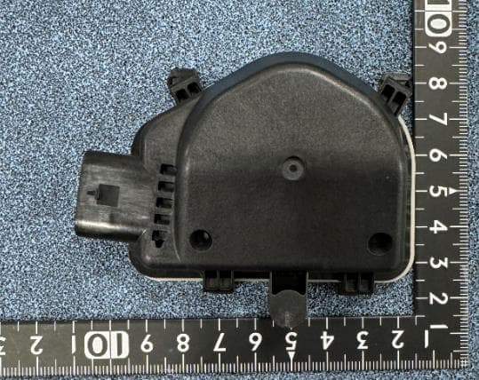
CWTB230X
Feb 07, 2024Sensor for opening and closing doors in cars
Equipment Class
FDS - Part 15 Field Disturbance Sensor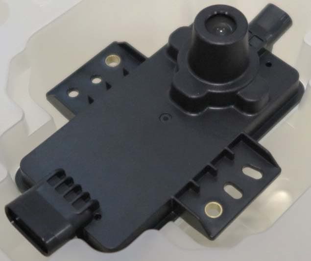
CWTB2211
Dec 26, 2023Automatic access gesture control
Equipment Class
DXX - Part 15 Low Power Communication Device Transmitter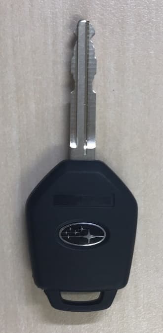
CWTB1G496
Aug 01, 2021KEYLESS ENTRY SYSTEM
Equipment Class
DSC - Part 15 Security/Remote Control Transmitter