CWTWB1U758Remote Keyless Entry Transmitter
ALPS ALPINE CO., LTD.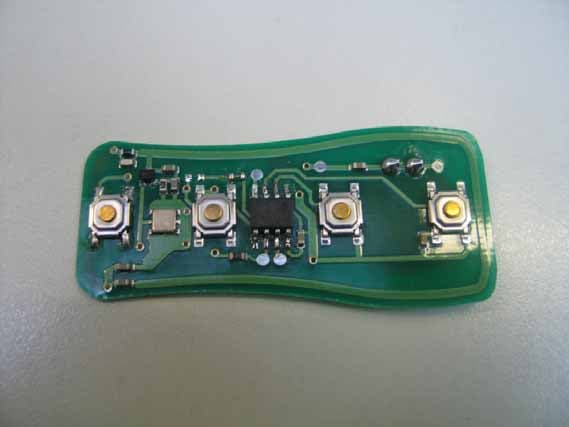
Click to zoom
Application Details
- Equipment Class
- DSR - Part 15 Remote Control/Security Device Transceiver
- Date of Grant
- Apr 23, 2007
- Application Purpose
- Original Equipment
- Date of Application
- Apr 23, 2007
- Equipment Note
- Remote Keyless Entry Transmitter
- Frequency Range
- 315.00000000 - 315.00000000
- Company
- ALPS ALPINE CO., LTD.
- Country
- Japan
Documents & Files
Document Text
Text extracted from the exhibit documents filed with the FCC. Open a document above to read the original.
Users Manual
Users Manual
External Photos
Test report Reference: MDE_ALPS_0703_FCCa Page 21 of 32 Photo 2: EUT (front side) Photo 3: EUT (rear side)
Internal Photos
Test report Reference: MDE_ALPS_0703_FCCa Page 22 of 32 Photo 4: EUT (enclosure) Photo 5: EUT (PCB front side) Test report Reference: MDE_ALPS_0703_FCCa Page 23 of 32 Photo 6: EUT (PCB bottom side)
Operational Description
Circuit Description TRANSMITTER The hand-held RF transmitter consists of the housing, three or four control buttons, micro-controller, an UHF oscillator (Colpits configuration) and a 3 volt battery. The micro-controller uses an internal oscillator running at 8.0 MHz, and the RF oscillator uses a SAW based oscillator to resonate at 315 MHz. The modulation format used will be ASK, with a Rolling/Manchester code data format. Once the user presses a button, power is applied to the micro-controller—which turns the RF oscillator on and off at the rate of the Keeloq (VPWM) protocol data being sent. The signal is then sent to the receiver module via RF data transmission. The module will then act upon the RF data received and will perform certain functions in correspondence to which transmitter button is pressed.
Test Report
7 layers AG Aufsichtsratsvorsitzenderh Registergerichth registered in: Borsigstrasse 11 Chairman of the Supervisory Board: Düsseldorf, HRB 44096 40880 Ratingen, Germany Markus Becker USt-IdNr h VAT Nr: Phone: +49 (0) 2102 749 0 Vorstandh Board: DE 203159652 Fax: +49 (0) 2102 749 350 Dr. Hans-Jürgen Meckelburg www.7Layers.com René Schildknecht InterLab ® is a registered trademark of 7 layers AG FCC Measurement/Technical Report on Vehicle remote keyless entry transmitter TFWB1U758 Nissan X61A Report Reference: MDE_ALPS_0703_FCCa Test Laboratory: 7 layers AG Borsigstrasse 11 40880 Ratingen Germany email: [email protected] DAT-P-192/99-01 Note: The following test results relate only to the devices specified in this document. This report shall not be reproduced in parts without the written approval of the testing laboratory. Test report Reference: MDE_ALPS_0703_FCCa Page 2 of 32 Table of Contents 0 Summary 3 0.1 Technical Report Summary 3 0.2 Measurement Summary 4 1 Administrative Data 5 1.1 Testing Laboratory 5 1.2 Project Data 5 1.3 Applicant Data 5 1.4 Manufacturer Data 5 2 Product labelling 6 2.1 FCC ID label 6 2.2 Location of the label on the EUT 6 3 Test object Data 7 3.1 General EUT Description 7 3.2 EUT Main components 8 3.3 Ancillary Equipment 8 3.4 EUT Setups 8 3.5 Operating Modes 8 4 Test Results 9 4.1 Spurious radiated emissions 9 4.2 Duty cycle measurement (based on dwell time measurement) 13 4.3 Peak power output 15 4.4 Occupied bandwidth 16 5 Test Equipment 17 6 Photo Report 20 7 Setup Drawings 24 8 Annex measurement plots 25 8.1 Radiated emissions (f<30MHz) 25 8.2 Duty cycle measurement (based on dwell time measurement) 26 Test report Reference: MDE_ALPS_0703_FCCa Page 3 of 32 0 Summary 0.1 Technical Report Summary Type of Authorization Certification for an Intentional Radiator (Periodic operation in the band above 70 MHz) Applicable FCC Rules Prepared in accordance with the requirements of FCC Rules and Regulations as listed in 47 CFR Ch.1 Parts 2 (10-1-06 Edition) and 15 (10-1-06 Edition). The following subparts are applicable to the results in this test report. Part 2, Subpart J - Equipment Authorization Procedures, Certification Part 15, Subpart C – Intentional Radiators § 15.201 Equipment authorization requirement § 15.207 Conducted limits § 15.209 Radiated emission limits; general requirements § 15.231 Periodic operation in the band 40.66-40.70 MHz, above 70 MHz Note: none Summary Test Results: The EUT complied with all performed tests as listed in chapter 0.2 Measurement Summary. Test report Reference: MDE_ALPS_0703_FCCa Page 5 of 32 1 Administrative Data 1.1 Testing Laboratory Company Name: 7 Layers AG Address Borsigstr. 11 40880 Ratingen Germany This facility has been fully described in a report submitted to the FCC and accepted under the registration number 96716. The test facility is also accredited by the following accreditation organisation: - Deutscher Akkreditierungs Rat DAR-Registration no. DAT-P-192/99-01 Responsible for Accreditation Scope: Dipl.-Ing. Bernhard Retka Dipl.-Ing. Robert Machulec Dipl.-Ing. Thomas Hoell Report Template Version: 2006-12-18 1.2 Project Data Responsible for testing and report: Dipl.-Ing. Robert Machulec Date of Test(s): 2007-02-12 to 2007-03-29 Date of Report: 2007-04-20 1.3 Applicant Data Company Name: Alps Automotive, Inc. Address: 1500 Atlantic Boulevard Auburn Hills, Michigan 48326 USA Contact Person: Mr. Joseph Keller 1.4 Manufacturer Data Company Name: please see applicant data Address: Contact Person: Test report Reference: MDE_ALPS_0703_FCCa Page 6 of 32 2 Product labelling 2.1 FCC ID label At the time of the report there was no FCC label available. 2.2 Location of the label on the EUT see above Test report Reference: MDE_ALPS_0703_FCCa Page 7 of 32 3 Test object Data 3.1 General EUT Description Equipment under Test Vehicle remote keyless entry transmitter Type Designation: TFWB1U758 Nissan X61A Kind of Device: (optional) 315 MHz transmitter Voltage Type: DC Voltage level: 3.0 V General product description: The vehicle remote keyless entry transmitter is a wireless handheld remote control unit(transmitter only, periodic operation in the band above 70 MHz). The operating frequency is 315 MHz. The transmitter is activated manually by a switch and is deactivated automatically within 5 seconds after release of the switch. The EUT provides the following ports: Ports Enclosure The main components of the EUT are listed and described in Chapter 3.2 Test report Reference: MDE_ALPS_0703_FCCa Page 8 of 32 3.2 EUT Main components Type, S/N, Short Descriptions etc. used in this Test Report Short Description Equipment under Test Type Designation Serial No. HW Status SW Status Date of Receipt EUT A (Code: 1H018b01) vehicle remote keyless entry transmitter TFWB1U758 Nissan X61A Test sample 1 Coded in type designation Coded in type designation 2007-02-12 Remark: EUT A is equipped with an integral antenna. NOTE: The short description is used to simplify the identification of the EUT in this test report. 3.3 Ancillary Equipment For the purposes of this test report, ancillary equipment is defined as equipment which is used in conjunction with the EUT to provide operational and control features to the EUT. It is necessary to configure the system in a typical fashion, as a customer would normally use it. But nevertheless Ancillary Equipment can influence the test results. Short Description Equipment under Test Type Designation HW Status SW Status Serial no. FCC ID – – – – – – – 3.4 EUT Setups This chapter describes the combination of EUTs and ancillary equipment used for testing. Setup No. Combination of EUT’s Description Setup_a01 EUT A setup for measurements 3.5 Operating Modes This chapter describes the operating modes of the EUT's used for testing. Op. Mode Description of Operating Modes Remarks op-mode 1 periodic operation Transmitter is sending a pulse coded signal op-mode 2 continuous operation Transmitter is sending a CW signal continuously…
Text truncated - open the document above for the full version.
Test Setup Photos
Test report Reference: MDE_ALPS_0703_FCCa Page 20 of 32 6 Photo Report Photo 1: Test setup for radiated measurements
Contact Information
Applicant
Yuji Ouchi
Technical Contact
ALPS Automotive Inc.Prudencio Cabigao
[email protected]248-391-5202
1500 Atlantic Boulevard · Auburn Hills, Michigan · United States
Test Firm
7layers AGRobert Machulec
Technical Specifications
| # | Rule Parts | Frequency Range | Power Output |
|---|---|---|---|
| 1 | 15.231 | 315 MHz - 315 MHz | - |
Other Applications from ALPS ALPINE CO., LTD.
CWTUMNZ1A2
Oct 06, 20245G Communication Module
Equipment Class
PCB - PCS Licensed TransmitterCWTB2311
Apr 09, 2024Automatic access gesture control
Equipment Class
DXX - Part 15 Low Power Communication Device Transmitter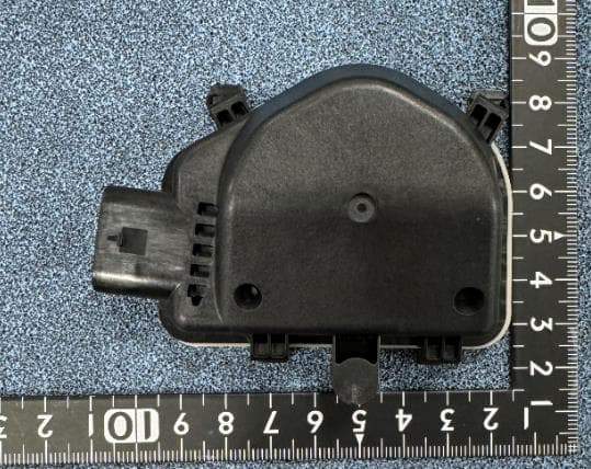
CWTB230X
Feb 07, 2024Sensor for opening and closing doors in cars
Equipment Class
FDS - Part 15 Field Disturbance Sensor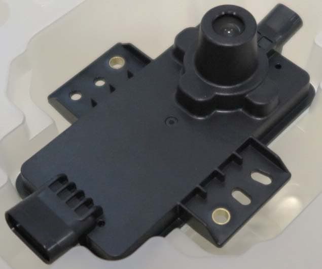
CWTB2211
Dec 26, 2023Automatic access gesture control
Equipment Class
DXX - Part 15 Low Power Communication Device Transmitter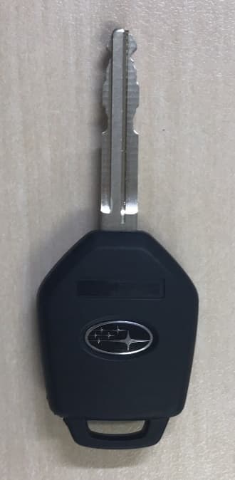
CWTB1G496
Aug 01, 2021KEYLESS ENTRY SYSTEM
Equipment Class
DSC - Part 15 Security/Remote Control Transmitter