CWTWC1U231Receiver of Tire Pressure Monitor Sensor
ALPS ALPINE CO., LTD.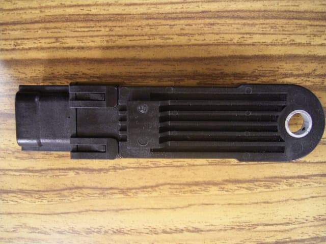
Click to zoom
Application Details
- Equipment Class
- CYY - Communications Receiver used w/Pt 15 Transmitter
- Date of Grant
- Jan 12, 2005
- Application Purpose
- Original Equipment
- Date of Application
- Jan 12, 2005
- Equipment Note
- Receiver of Tire Pressure Monitor Sensor
- Frequency Range
- 314.98000000 - 314.98000000
- Company
- ALPS ALPINE CO., LTD.
- Country
- Japan
Documents & Files
Document Text
Text extracted from the exhibit documents filed with the FCC. Open a document above to read the original.
Users Manual
c. You notice a change in the sound of the exhaust system. d. You have had an accident involving damage to the exhaust system, un- derbody, or rear of the vehicle. THREE-WAY CATALYST The three-way catalyst is an emission control device installed in the exhaust system. Exhaust gases in the three-way catalyst are burned at high temperatures to help reduce pollutants. WARNING OThe exhaust gas and the exhaust system are very hot. Keep people, ani- mals or flammable materials away from the exhaust system components. ODo not stop or park the vehicle over flammable materials such as dry grass, waste paper or rags. They may ignite and cause a fire. CAUTION ODo not use leaded gasoline. Deposits from leaded gasoline seriously reduce the three-way catalyst's ability to help reduce exhaust pollutants. OKeep your engine tuned up. Malfunc- tions in the ignition, fuel injection, or electrical systems can cause overrich fuel flow into the three-way catalyst, causing it to overheat. Do not keep driving if the engine misfires, or if no- ticeable loss of performance or other unusual operating conditions are de- tected. Have the vehicle inspected promptly by an INFINITI dealer. OAvoid driving with an extremely low fuel level. Running out of fuel could cause the engine to misfire, damaging the three-way catalyst. ODo not race the engine while warming it up. LOW TIRE PRESSURE WARNING SYSTEM This vehicle is equipped with the low tire pressure warning system. It monitors tire pressure of all tires except the spare. When the low tire pressure warning light is lit, one or more of your tires is signifi- cantly underinflated. The system also dis- plays pressure of all tires (except the spare tire) on the display screen by send- ing a signal from a sensor that is installed in each wheel. The low tire pressure warning system will activate only when the vehicle is driven at speeds above 20 MPH (32 km/h). Also, this system may not detect a sudden drop in tire pressure (for example, a flat tire while driving). Tire pressure rises and falls depending on the heat caused by the vehicle's operation and the outside temperature. Low outside temperature can lower the temperature of the air inside the tire which can cause a lower tire inflation pressure. This may cause the low tire pressure warning light to illuminate. If the warning light illuminates in low out- side temperatures as described above, check the tire pressure for all four tires. Starting and driving5-3 Z04.12.13/Y50-DX Adjust the tire pressure to the recom- mended COLD tire pressure shown on the Tire and Loading Information label to turn the low tire pressure warning light OFF. Frequently check the tire pressure informa- tion display on the monitor screen and ad- just pressure of each tire properly. See ™Vehicle information and settings∫ in the ™4. Monitor, climate, audio, phone and voice recognition systems∫ section for tire pressure monitor. Low tire pressure warning If the vehicle is being driven with low tire pressure (lower than 27 psi, 190 kPa), the LOW PRESSURE information message will be displayed on the monitor screen. The low tire pressure warning light comes on, and the chime sounds for about 10 sec- onds. If you select the tire pressure information in the display, the LOW PRESSURE informa- tion message will be displayed. For additional information regarding the above warning, see ™Warning/indicator lights and audible reminders∫ in the ™2. Instruments and controls∫ section. WARNING OIf the low tire pressure warning light flashes while driving, avoid sudden steering maneuvers or abrupt braking, reduce vehicle speed, pull off the road to a safe location and stop the vehicle as soonaspossible.Seriousvehicle damage could occur and may lead to an accident and could result in serious per- sonal injury. Check the pressure for all four tires. Adjust the pressure to the rec- ommended COLD tire pressure shown on the Tire and Loading Information label to turn the low tire pressure warning light OFF. If you have a flat tire, replace it with a spare tire as soon as possible. (See ™Flat tire∫ in the ™6. In case of emer- gency∫ section for changing a flat tire.) OIf your vehicle is equipped with run-flat tires, you can continue driving after you have a flat tire. However, remember that vehicle handling stability is reduced, whichcouldleadtoanaccident and personal injury. See ™Wheels and tires∫ in the ™8. Maintenance and do-it- yourself∫ section for more details and make sure to observe the cautions about run-flat tires. Failure to do so may result in a serious accident. OImmediatelyafterasparetireis mounted or a wheel is replaced, tire pres- sure will not be indicated on the display and the low tire pressure warning system will not function. Reset the system by driving the vehicle at over 25 MPH (40 km/h) for approximately 10 minutes. If tire pressure is not indicated after per- forming the resetting procedure above, contact an INFINITI dealer as soon as possible. OReplacing tires with those not originally specified by INFINITI could affect the proper operation of the low tire pressure warning system. ODo not inject any tire liquid or aerosol tire sealant into the tires, as this may cause a malfunction of the tire pressure sensors. 5-4Starting and driving Z04.12.21/Y50-DX CAUTION The low tire pressure warning system may not function properly when the wheels are equipped with tire chains or the wheels are buried in snow. FCC Notice: Changes or modifications not expressly approved by the manufacturer compliance could void the user's authority to operate the equipment. This device complies with Part 15 of the FCC Rules and RSS-210 of Industry Canada. Operation is subject to the following two conditions: (1) This device may not cause harmful interference, and (2) this device must accept any interference received, in- cluding interference that may cause un- desired operation of the device. AVOIDING COLLISION AND ROLLOVER WARNING Failure to operate this vehicle in a safe a…
Text truncated - open the document above for the full version.
External Photos
Alps Electric Co., Ltd. FCC ID: CWTWC1U231 IC No.: 1788D-FWC1U231 External Photo Side A Side B
Internal Photos
Alps Electric Co., Ltd. FCC ID: CWTWC1U231 IC No.: 1788D-FWC1U231 Internal Photo Side A Side B
Test Report
Test report No. : 25DE0199-HO-1 Page : 2 of 12 Issued date : December 27, 2004 FCC ID : CWTWC1U231 Revised date : January 7, 2005 UL Apex Co., Ltd. Head Office EMC Lab. 4383-326 Asama-cho, Ise-shi, Mie-ken 516-0021 JAPAN Telephone : +81 596 24 8116 Facsimile : +81 596 24 8124 MF060b(10.04.03) CONTENTS PAGE SECTION 1: Client information...................................................................................................... 3 SECTION 2: Equipment under test (E.U.T.) ................................................................................. 3 SECTION 3: Test specification, procedures & results .................................................................. 4 SECTION 4: Operation of E.U.T. during testing........................................................................... 5 SECTION 5: Radiated Emission ..................................................................................................... 6 APPENDIX 1: Photographs of test setup........................................................................................ 7 Radiated Emission.............................................................................................................................................. 7 Worst Case Position (Horizontal : X-axis/ Vertical: X-axis) .......................................................................... 8 APPENDIX 2:Test instruments ........................................................................................................ 9 APPENDIX 3: Data of EMI test ..................................................................................................... 10 Radiated Emission............................................................................................................................................ 10 Test report No. : 25DE0199-HO-1 Page : 3 of 12 Issued date : December 27, 2004 FCC ID : CWTWC1U231 Revised date : January 7, 2005 UL Apex Co., Ltd. Head Office EMC Lab. 4383-326 Asama-cho, Ise-shi, Mie-ken 516-0021 JAPAN Telephone : +81 596 24 8116 Facsimile : +81 596 24 8124 MF060b(10.04.03) SECTION 1: Client information Company Name : Alps Electric Co., Ltd. Address : 6-3-36 Nakazato, Furukawa-City Miyagi-pref., 989-6181 Japan Telephone Number : +81-229-23-5111 Facsimile Number : +81-229-22-3755 Contact Person : Saori Mukai SECTION 2: Equipment under test (E.U.T.) 2.1 Identification of E.U.T. Type of Equipment : Receiver of Tire Pressure Monitoring Sensor Model No. : TFWC1U231 Sample No. : 40909178 Country of Manufacture : Japan Rating : DC12V Receipt Date of Sample : November 24, 2004 Condition of EUT : Production prototype (Not for Sale: This sample is equivalent to mass-produced items.) 2.2 Product Description Model No: TFWC1U231 is Receiver of Tire Pressure Monitoring Sensor. The EUT receives the RF signal from the air pressure monitor transmitter and demodulates received signal. Then, EUT outputs digital data and RSSI voltage to ECU. Type of receiver : Super Heterodyne Receiving Frequency : 314.98MHz Operating temperature range : -30 to - +70deg.C. The receiving antenna (of this EUT) is installed on the Tire Pressure Monitoring Sensor, which is unremovable. Therefore, this EUT complies with the requirement in section 15.111(b). Test report No. : 25DE0199-HO-1 Page : 4 of 12 Issued date : December 27, 2004 FCC ID : CWTWC1U231 Revised date : January 7, 2005 UL Apex Co., Ltd. Head Office EMC Lab. 4383-326 Asama-cho, Ise-shi, Mie-ken 516-0021 JAPAN Telephone : +81 596 24 8116 Facsimile : +81 596 24 8124 MF060b(10.04.03) SECTION 3: Test specification, procedures & results 3.1 Test specification Test Specification FCC Part15 Subpart B : 2004 Class B FCC 47CFR Part15 Radio Frequency Device Subpart B Unintentional Radiators 3.2 Procedures and results Item Test Procedure Limits Deviation Worst margin ** Result Conducted emission ANSI C63.4: 2003 Class B N/A N/A*1) N/A Radiated emission ANSI C63.4: 2003 Class B N/A 20.0dB 945.00MHz, QP Horizontal/Vertical Complied *Note: UL Apex’s EMI Work Procedure QPM05. ** The result is rounded off to the second decimal place. Therefore, there may be 0.1 difference for the result. *1) The test is not applicable since the EUT does not have AC Mains. *These tests were performed without any deviations from test procedure except for additions or exclusions. 3.3 Uncertainty Radiated Emission The measurement uncertainty (with a 95% confidence level) for this test using Biconical antenna is ±4.5dB(3m). The measurement uncertainty (with a 95% confidence level) for this test using Logperiodic antenna is ±5.2dB(3m). The measurement uncertainty (with a 95% confidence level) for this test using Horn antenna is ±6.6dB(3m). The data listed in this test report has enough margin. 3.4 Test Location UL Apex Co., Ltd. Head Office EMC Lab. *NVLAP Lab. code: 200572-0 4383-326 Asama-cho, Ise-shi, Mie-ken 516-0021 JAPAN Telephone : +81 596 24 8116 Facsimile : +81 596 24 8124 Listed date (for FCC) FCC Registration Number IC Registration Number Width x Depth x Height (m) Size of reference ground plane (m) / horizontal conducting plane Other rooms No.1 semi-anechoic chamber February 01, 2002 313583 IC4247 19.2 x 11.2 x 7.7m 7.0 x 6.0m Preparation room No.2 semi-anechoic chamber June 05, 2002 846015 IC4247-2 7.5 x 5.8 x 5.2m 4.0 x 4.0m - No.3 shielded room - - - 4.7 x 7.5 x 2.7m 4.7 x 7.5m - No.4 measurement room - - - 3.1 x 5.0 x 2.7m N/A - * Size of vertical conducting plane (for Conducted Emission test) : 2.0 x 2.0m for No.1 and No.2 semi-anechoic and No.3 shielded room. 3.5 Test set up, Test instruments and Data of EMI Refer to APPENDIX 1 to 3. Test report No. : 25DE0199-HO-1 Page : 5 of 12 Issued date : December 27, 2004 FCC ID : CWTWC1U231 Revised date : January 7, 2005 UL Apex Co., Ltd. Head Office EMC Lab. 4383-326 Asama-cho, Ise-shi, Mie-ken 516-0021 JAPAN Telephone : +81 596 24 8116 Facsimile : +81 596 24 8124 MF060b(10.04.03) SECTION 4: Operation of E.U.T. during testing 4.1 Operating modes Test sequence…
Text truncated - open the document above for the full version.
Contact Information
Applicant
Yuji Ouchi
Technical Contact
UL Apex Co.,LtdKeiichi Aoki
[email protected]+81-596-24-8116
4383-326 Asama-cho · Ise-shi, Mie-ken · Japan
Non-Technical Contact
UL Apex Co., LtdYukari Ito
[email protected]+81-596-24-8116
Test Firm
UL Apex Co., Ltd.Tetsuya Hashimoto
Technical Specifications
| # | Rule Parts | Frequency Range | Power Output |
|---|---|---|---|
| 1 | 15B | 314.98 MHz - 314.98 MHz | - |
Other Applications from ALPS ALPINE CO., LTD.
CWTUMNZ1A2
Oct 06, 20245G Communication Module
Equipment Class
PCB - PCS Licensed TransmitterCWTB2311
Apr 09, 2024Automatic access gesture control
Equipment Class
DXX - Part 15 Low Power Communication Device Transmitter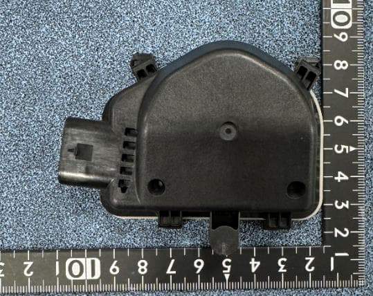
CWTB230X
Feb 07, 2024Sensor for opening and closing doors in cars
Equipment Class
FDS - Part 15 Field Disturbance Sensor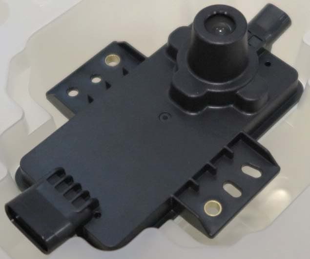
CWTB2211
Dec 26, 2023Automatic access gesture control
Equipment Class
DXX - Part 15 Low Power Communication Device Transmitter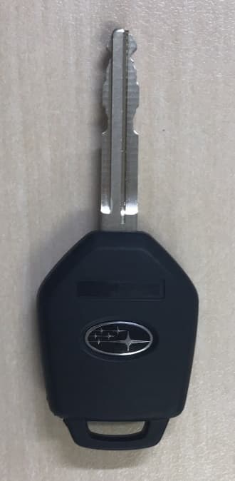
CWTB1G496
Aug 01, 2021KEYLESS ENTRY SYSTEM
Equipment Class
DSC - Part 15 Security/Remote Control Transmitter