CWTWC1U283Passive Entry System (Tuner)
ALPS ALPINE CO., LTD.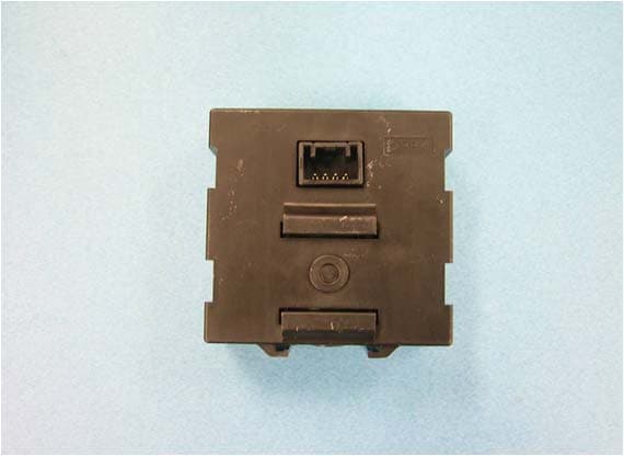
Click to zoom
Application Details
- Equipment Class
- CYY - Communications Receiver used w/Pt 15 Transmitter
- Date of Grant
- Jun 19, 2012
- Application Purpose
- Original Equipment
- Date of Application
- Jun 19, 2012
- Equipment Note
- Passive Entry System (Tuner)
- Frequency Range
- 315.00000000 - 315.00000000
- Company
- ALPS ALPINE CO., LTD.
- Country
- Japan
Documents & Files
Document Text
Text extracted from the exhibit documents filed with the FCC. Open a document above to read the original.
Users Manual
User’s Manual MODEL No.: TWC1U283 The radio frequency keyless entry system has the following functions. 1. Locking and unlocking the doors without mechanical key. 2. Sounding a panic alarm during vehicle is not running. This system consists of RF Tuner, transmitters, and BCM. The RF Tuner (EUT) is supplied 5V from BCM. It is designed to operate on a single fixed frequency RF 315MHz by amplitude modulation. It receives unique identification code and function code transmitted from transmitters. After receiving RF signal, demodulation IC in Tuner demodulates RF signal from transmitters. And then driving circuit in Tuner outputs the demodulated signal to BCM. ・Basic specifications Operating supply voltage 4.5V ~ 5.5V Operating supply current < 12mA Stand-by current < 1.0mA Operating ambient temperature -40 o C to +85 o C FCC CAUTION Changes or modifications not expressly approved by the party responsible for compliance could void the user’s authority to operate the equipment. This device complies with part 15 of the FCC Rules. Operation is subject to the following two conditions: (1) This device may not cause harmful interference, and (2) this device must accept any interference received, including interference that may cause undesired operation. ・Radio Law of Thailand This telecommunication equipment conforms to NTC technical requirement.
External Photos
External Photo
ID Label/Location Info
1
Internal Photos
Internal Photo Without shield case
Test Report
Test report No. : 32GE0143-HO-01-A Page : 2 of 12 Issued date : June 4, 2012 FCC ID : CWTWC1U283 UL Japan, Inc. Head Office EMC Lab. 4383-326 Asama-cho, Ise-shi, Mie-ken 516-0021 JAPAN Telephone : +81 596 24 8116 Facsimile : +81 596 24 8124 CONTENTS PAGE SECTION 1: Customer information ...................................................................................... 3 SECTION 2: Equipment under test (E.U.T.) ........................................................................ 3 SECTION 3: Test specification, procedures & results ......................................................... 4 SECTION 4: Operation of E.U.T. during testing ................................................................. 6 SECTION 5: Radiated Emission ............................................................................................ 7 APPENDIX 1: Data of EMI test ............................................................................................. 8 Radiated Emission ............................................................................................................................ 8 APPENDIX 2: Test instruments ........................................................................................... 10 APPENDIX 3: Photographs of test setup............................................................................. 11 Radiated Emission .......................................................................................................................... 11 Worst Case Position (Horizontal: X-axis/ Vertical:X-axis) ........................................................ 12 Test report No. : 32GE0143-HO-01-A Page : 3 of 12 Issued date : June 4, 2012 FCC ID : CWTWC1U283 UL Japan, Inc. Head Office EMC Lab. 4383-326 Asama-cho, Ise-shi, Mie-ken 516-0021 JAPAN Telephone : +81 596 24 8116 Facsimile : +81 596 24 8124 SECTION 1: Customer information Company Name : Alps Electric Co., Ltd. Address : 6-3-36, Nakazato, Furukawa, Osaki-city, Miyagi-pref, 989-6181, Japan Telephone Number : +81-229-23-5111 Facsimile Number : +81-229-22-3755 Contact Person : Toru Kinoshita SECTION 2: Equipment under test (E.U.T.) 2.1 Identification of E.U.T. Type of Equipment : Passive Entry System (Tuner) Model No. : TWC1U283 Serial No. : Refer to Section 4, Clause 4.2 Receipt Date of Sample : May 20, 2012 Country of Mass-production : Japan Condition of EUT : Production prototype (Not for Sale: This sample is equivalent to mass-produced items.) Modification of EUT : No Modification by the test lab 2.2 Product Description Model No: TWC1U283 (referred to as the EUT in this report) is the Passive Entry System (Tuner). Feature of EUT: This unit receives the RF output signal from the FOB (Transmitter) in response to several switch operations. This unit sends detected signal to the Controller through Signal and RSSI outputs. The Controller provides operations according to receiving signals. Clock frequency(ies) in the system : 29.5533MHz (Oscillator circuit) Type of Receiver : Super hetrodyne Frequency of Operation : 315MHz Oscillator Frequency : 29.5533MHz (Crystal) Local Oscillator Frequency : 315.235MHz (29.5533MHz x1/3 x32) Intermediate Frequency : 235kHz Antenna Type : Internal Antenna (Monopole) Method of Frequency Generation : Crystal Operating voltage (Inner) : DC 4.5 V to 5.5V Operating temperature range : -40 deg. C to +85 deg. C FCC15.111(b) The receiving antenna (of this EUT) is installed inside the EUT and cannot be removed (permanently attached). Therefore, Radiated emission test was performed. Test report No. : 32GE0143-HO-01-A Page : 4 of 12 Issued date : June 4, 2012 FCC ID : CWTWC1U283 UL Japan, Inc. Head Office EMC Lab. 4383-326 Asama-cho, Ise-shi, Mie-ken 516-0021 JAPAN Telephone : +81 596 24 8116 Facsimile : +81 596 24 8124 SECTION 3: Test specification, procedures & results 3.1 Test specification Test Specification : FCC Part 15 Subpart B: 2012, final revised on March 30, 2012 and effective April 30, 2012 Title : FCC 47CFR Part15 Radio Frequency Device Subpart B Unintentional Radiators 3.2 Procedures and results Item Test Procedure Limits Deviation Worst margin Result Conducted emission FCC: ANSI C63.4: 2003 7. AC powerline conducted emission measurements FCC: Part 15 Subpart B 15.107(a) N/A *1) N/A N/A IC: RSS-Gen 7.2.4 IC: RSS-Gen 7.2.4 Radiated emission FCC: ANSI C63.4: 2003 8. Radiated emission measurements FCC: Part 15 Subpart B 15.109(a) N/A 16.5dB 945.705MHz Horizontal, QP Complied IC: RSS-Gen 4.10 IC: RSS-Gen 6.1 *Note: UL Japan, Inc’s EMI Work Procedure 13-EM-W0420. *1) The test is not applicable since the EUT is not the device that is designed to be connected to the public utility (AC) power line. 3.3 Addition to standard No addition, exclusion nor deviation has been made from the standard. 3.4 Uncertainty EMI The following uncertainties have been calculated to provide a confidence level of 95% using a coverage factor k=2. Test room (semi- anechoic chamber) Radiated emission (3m*)(+dB) (1m*)(+dB) (0.5m*)(+dB) 9kHz -30MHz 30MHz -300MHz 300MHz -1GHz 1GHz -10GHz 10GHz -18GHz 18GHz -26.5GHz 26.5GHz -40GHz No.1 4.2dB 5.0dB 5.1dB 4.7dB 5.7dB 4.4dB 4.3dB No.2 4.1dB 5.2dB 5.1dB 4.8dB 5.6dB 4.3dB 4.2dB No.3 4.5dB 5.0dB 5.2dB 4.8dB 5.6dB 4.5dB 4.2dB No.4 4.7dB 5.2dB 5.2dB 4.8dB 5.6dB 5.1dB 4.2dB *3m/1m/0.5m = Measurement distance Radiated emission test(3m) The data listed in this test report has enough margin, more than the site margin. Test report No. : 32GE0143-HO-01-A Page : 5 of 12 Issued date : June 4, 2012 FCC ID : CWTWC1U283 UL Japan, Inc. Head Office EMC Lab. 4383-326 Asama-cho, Ise-shi, Mie-ken 516-0021 JAPAN Telephone : +81 596 24 8116 Facsimile : +81 596 24 8124 3.5 Test Location UL Japan, Inc. Head Office EMC Lab. *NVLAP Lab. code: 200572-0 4383-326 Asama-cho, Ise-shi, Mie-ken 516-0021 JAPAN Telephone : +81 596 24 8116 Facsimile : +81 596 24 8124 FCC Registration Number IC Registration Number Width x Depth x Height (m) Size of reference ground plane (m) / horizontal conducting…
Text truncated - open the document above for the full version.
Test Setup Photos
Test report No. : 32GE0143-HO-01-A Page : 11 of 12 Issued date : June 4, 2012 FCC ID : CWTWC1U283 UL Japan, Inc. Head Office EMC Lab. 4383-326 Asama-cho, Ise-shi, Mie-ken 516-0021 JAPAN Telephone : +81 596 24 8116 Facsimile : +81 596 24 8124 APPENDIX 3: Photographs of test setup Radiated Emission Photo 1 Photo 2 Test report No. : 32GE0143-HO-01-A Page : 12 of 12 Issued date : June 4, 2012 FCC ID : CWTWC1U283 UL Japan, Inc. Head Office EMC Lab. 4383-326 Asama-cho, Ise-shi, Mie-ken 516-0021 JAPAN Telephone : +81 596 24 8116 Facsimile : +81 596 24 8124 Worst Case Position (Horizontal: X-axis/ Vertical:X-axis) X-axis Y-axis Z-axis
Contact Information
Applicant
Yuji Ouchi
Technical Contact
UL Japan, Inc.Masanori Nishiyama
[email protected]81-596-24-8116
4383-326 Asama-cho, Ise-shi · Mie-ken · Japan
Test Firm
UL Japan, Inc. Head office EMC Lab.Tetsuya Hashimoto
Technical Specifications
| # | Rule Parts | Frequency Range | Power Output |
|---|---|---|---|
| 1 | 15B | 315 MHz - 315 MHz | - |
Other Applications from ALPS ALPINE CO., LTD.
CWTUMNZ1A2
Oct 06, 20245G Communication Module
Equipment Class
PCB - PCS Licensed TransmitterCWTB2311
Apr 09, 2024Automatic access gesture control
Equipment Class
DXX - Part 15 Low Power Communication Device Transmitter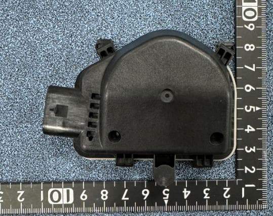
CWTB230X
Feb 07, 2024Sensor for opening and closing doors in cars
Equipment Class
FDS - Part 15 Field Disturbance Sensor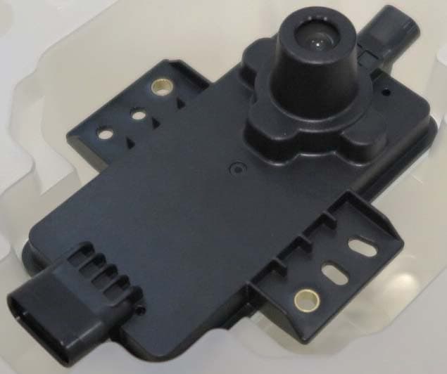
CWTB2211
Dec 26, 2023Automatic access gesture control
Equipment Class
DXX - Part 15 Low Power Communication Device Transmitter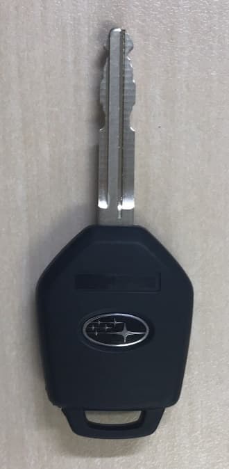
CWTB1G496
Aug 01, 2021KEYLESS ENTRY SYSTEM
Equipment Class
DSC - Part 15 Security/Remote Control Transmitter